Pump Handbook by Igor J. Karassik, Joseph P. Messina, Paul Cooper, Charles C. Heald - 3rd edition
Подождите немного. Документ загружается.

9.16.3 CONSTRUCTION OF SOLIDS-HANDLING DISPLACEMENT PUMPS 9.375
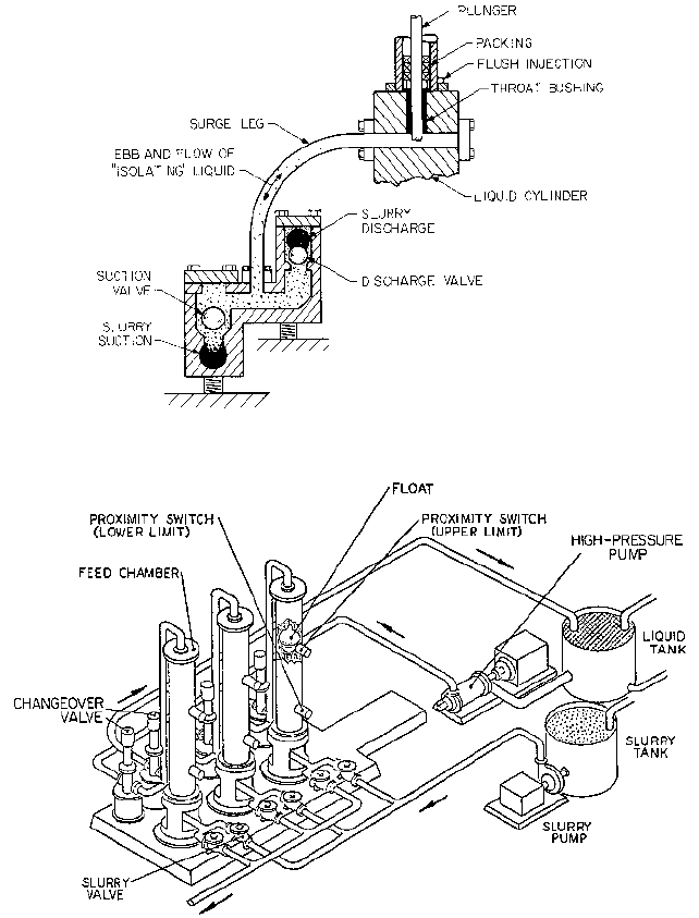
FIGURE 7 Surge leg plunger pump
FIGURE 8 Large, low-cycle chamber feeders separate the high-pressure pumping element from the slurry
(Hitachi)
chamber. Therefore special construction materials, flush injection, and reduced speeds are
still appropriate.
SEPARATION OF SLURRY FROM PUMPING ELEMENT A special case of the liquid leg pump is the
large, low-cycle chamber feeder (Figure 8). Although these units may or may not properly
qualify as positive displacement pumps (because the motivating liquid may be delivered
by a centrifugal pump), they do nevertheless have much in common with surge leg pumps.
9.376 CHAPTER NINE
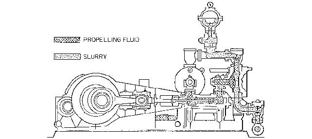
FIGURE 9 Diaphragm pump isolates slurry from packing (Geho)
The motivating liquid is pumped into a chamber and displaces a charge of slurry
through suitable check valves. The chamber may have a moving separation barrier
between the motivating and motivated liquids.When the slurry is expelled, controls cause
valves to reverse the flow, filling the chamber again with slurry while voiding it of the clear
liquid. By employing two or more chambers, a virtually continuous flow of slurry is
obtained. Advantages of this scheme are the extra-low frequency of check valve operation,
low slurry velocities, and high capacities. Centrifugal, positive displacement, or even com-
pressed gas pumps can be used for motivation. Because the motivation pump is indepen-
dent of the slurry system, it can operate at normal speed.
Two disadvantages of chamber feeders are their dependence on controls and switching
valves in addition to the slurry valves and the fact that the systems are large.
TOTAL ISOLATION
Many types of diaphragm pumps that completely separate the slurry
from the running gear of the pump have been designed (Figure 9). Because the separat-
ing diaphragm is wetted on one side by the slurry, it is vulnerable to the mechanical, chem-
ical, and thermal abuse that might otherwise apply to pistons, plungers, packing, and so
on. Of course, the diaphragm is also subjected to full reversal loads and must be designed
for fatigue life. Both elastomeric and metallic diaphragms have been used.
The severity of diaphragm failure problems has been alleviated somewhat in some
designs that employ double diaphragms with intervening barrier liquids. The thesis is
that there is a much reduced probability of both diaphragms failing before detection and
repair.
DIAGNOSTIC SYSTEMS _______________________________________________
Diagnostic monitoring of vibration, pressure pulsations, speed, flow rate, temperatures,
and pressures may be applied to these pumps as well as other large machines. Such mon-
itoring is relevant to slurry pumps because of the necessity to replace worn parts more fre-
quently than is the case with clear-liquid pumps. Designers and users of displacement
pumps for handling solids should consider using available monitoring equipment as an aid
to maintenance and as a means to ensure the safety of personnel by warning of imminent
failure. Vibration signatures are readily obtained from sensors placed in critical locations
on the pump, and this information can be valuable in assessing the operating integrity of
the pump. To this should be added valve wear detection, as would be indicated by a dif-
ference between the expected flow rate at the speed involved and the actual flow rate. In
addition, proximity probes and vibration sensors could be used to monitor wear of
plungers, piston rods, bearings, and crossheads.

JOHN R. BRENNAN
WILLIAM M. VANCE
9.377
SECTION 9.17
OIL WELLS
°1 bar 10
5
Pa.
ARTIFICIAL LIFT OF OIL WELLS ________________________________________
Oil wells can range in depth from approximately 200 ft (60 m) to more than 20,000 ft
(6000 m). They require pumps that are unique in their configuration. About 90% of pump-
ing oil wells are equipped with either 2-in (50.8-mm) or 2 in (61.9-mm) ID tubing. Sucker
rod pumps, hydraulic reciprocating pumps, or hydraulic jet pumps that must run inside
this tubing cannot have their outside diameters exceed 1 in (47.6 mm) or 2 in (58.7 mm).
These pumps are installed as close as possible to the bottom in order to achieve the max-
imum possible drawdown of fluid in the well. The output pressure required of the pump
varies directly with the depth that the fluid must be lifted. For example, to compensate for
the lift required and the fluid friction in the tubing, a 10,000-ft (3049-m) well might
require a 4000-lb/in
2
(276-bar°) pump.
In a newly discovered field, wells will usually flow of their own accord and require no
artificial lift. The volume from these wells is controlled by holding back pressure at the
wellhead with a choke. The annulus between the production tubing and the oil well cas-
ing is closed off at the wellhead; thus all of the gas produced by the well flows up the pro-
duction tubing with the oil. When the bottom hole pressure is no longer adequate to
produce the well by natural flow, some form of artificial lift must be installed. This can be
a sucker rod pump, a subsurface hydraulic reciprocating pump, a subsurface hydraulic jet
pump, an electric submersible centrifugal pump, or a gas lift. The sucker rod pump is by
far the most common form of artificial lift. More than 80% of the wells that must be arti-
ficially lifted are pumped with sucker rod pumps.
5
16
7
8
7
16
9.378 CHAPTER NINE
*In oil field terminology, an upset is an enlarged portion formed on the end of the rod by forging.This allows for a joint
that is stronger than the body of the rod.
THE SUCKER ROD PUMPING SYSTEM __________________________________
The sucker rod pumping system consists of a prime mover, a pumping unit, a polished rod
with a stuffing box to seal off the pumped fluid pressure at the surface of the well, and a
sucker rod string to transmit the reciprocating movement from the pumping unit to the
sucker rod pump.The pumping unit is the mechanism that converts the rotary movement
of the prime mover to the reciprocating movement needed to power the sucker rod pump.
The sucker rod string consists of individual sucker rods of 25- or 30-ft (7.6- or 9.1-m)
lengths that are connected with couplings when they are lowered into the well. This total
length of rods connects the surface polished rod to the pump at the bottom and is called the
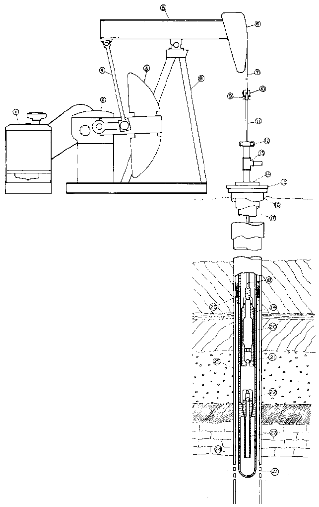
sucker rod string. The complete sucker rod pumping system is illustrated in Figure 1.
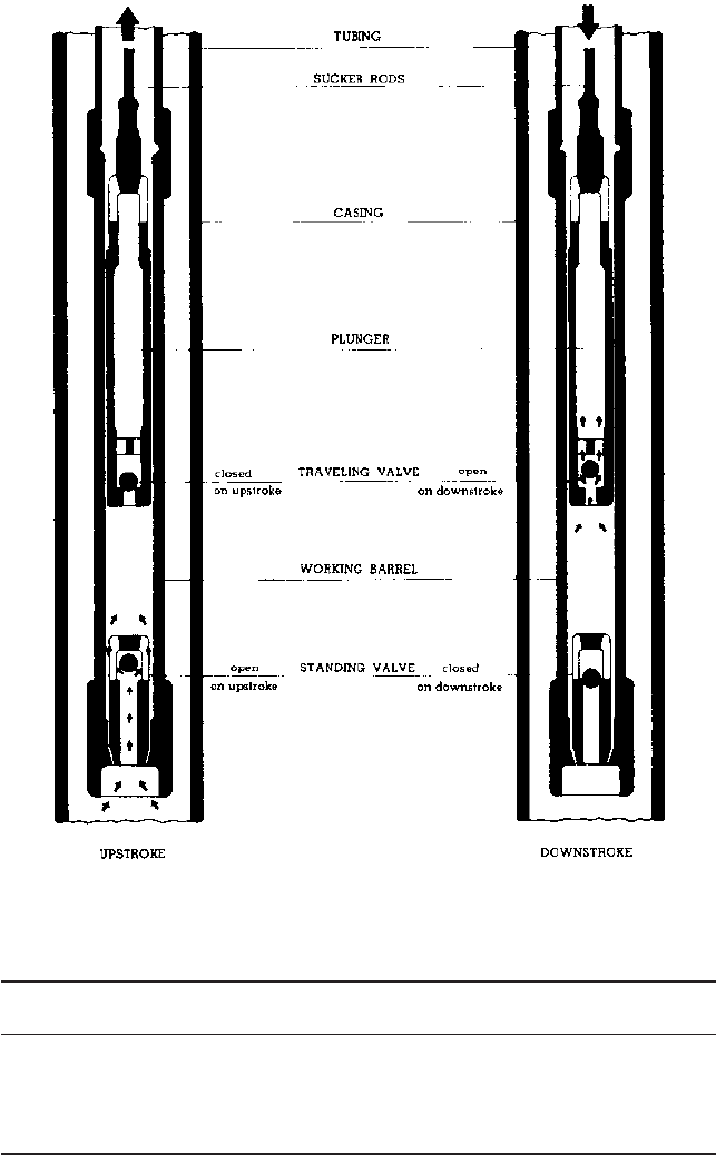
The operation of a sucker rod pump is illustrated in Figure 2. The pump is submerged
in fluid near the bottom of the oil well. As the sucker rod string and plunger make an
upstroke, fluid from the well bore flows past the standing valve into the pump barrel. Also
on this upstroke, the traveling valve is closed and the fluid above the plunger is pumped
up the annulus between the sucker rod string and the tubing string. On the downstroke,
the traveling valve is open and the standing valve is closed. The fluid in the pumping
chamber between the traveling valve and standing valve is displaced into the annulus
between the tubing and the sucker rod string above the plunger. The fluid in the annulus
is lifted toward the surface only on the upstroke.
The Sucker Rod Pump The principal parts of the sucker rod pump are the barrel,
plunger, traveling valve, and standing valve. These are seen in a cutaway section in Fig-
ure 3. In shallow wells relatively free of sand, soft-packed plungers are frequently used.
These have a number of fabric rings or cups that are expanded by the pumping pressure
to a close fit with the barrel. In deep wells or in hard-to-pump shallow wells, the preci-
sion-fit metal barrel and plunger as shown in Figure 3 are used. The most common pre-
cision barrel is made from steel tubing with a case-hardened or induction-hardened inside
wear surface. The inside diameter of the barrel is honed to the nominal bore size with a
tolerance of ;0.001 in (0.025 mm). Premium barrels are chrome-plated on the inside diam-
eter to a thickness of 0.003 in (0.076 mm) per side. Material for these barrels may be car-
bon or stainless steel, brass or Monel. The brass or Monel tubes are used when hydrogen
sulfide, carbon dioxide, and brine mixed with produced fluid create an extremely corro-
sive condition. More common barrel lengths range from 5 to 24 ft (1.5 to 7.3 m), but longer
lengths are available for use with very long-stroke surface units.
There are several kinds of plungers. A chrome-plated one-piece plunger or a plunger
made of hard cast alloy iron sections assembled over a steel plunger tube is usually used
with the precision hardened steel barrel. A plunger that is hard-faced with a nickel-based
spray metal material is usually used with the chrome-lined barrel, although the cast
plunger can also be used there. Plungers range from 2 to 6 ft (0.6 to 1.8 m) in length,
depending on the depth of the well. These plungers are all ground to a precision tolerance
of 0.0000, 0.0005 in (0.000, 0.013 mm). The diametral fit between the inside of the
barrel and the outside of the plunger ranges from 0.002 to 0.005 in (0.05 to 0.13 mm),
depending on the quality of the well fluid and the diameter and length of the plunger.
The traveling valve and standing valve of the pump are simple ball-and-seat check
valves.Type 440 hardened stainless steel materials are the most common, but in corrosive
wells, a cobalt-chromium-tungsten alloy is frequently used, and in very abrasive wells
tungsten carbide seats and balls are used.
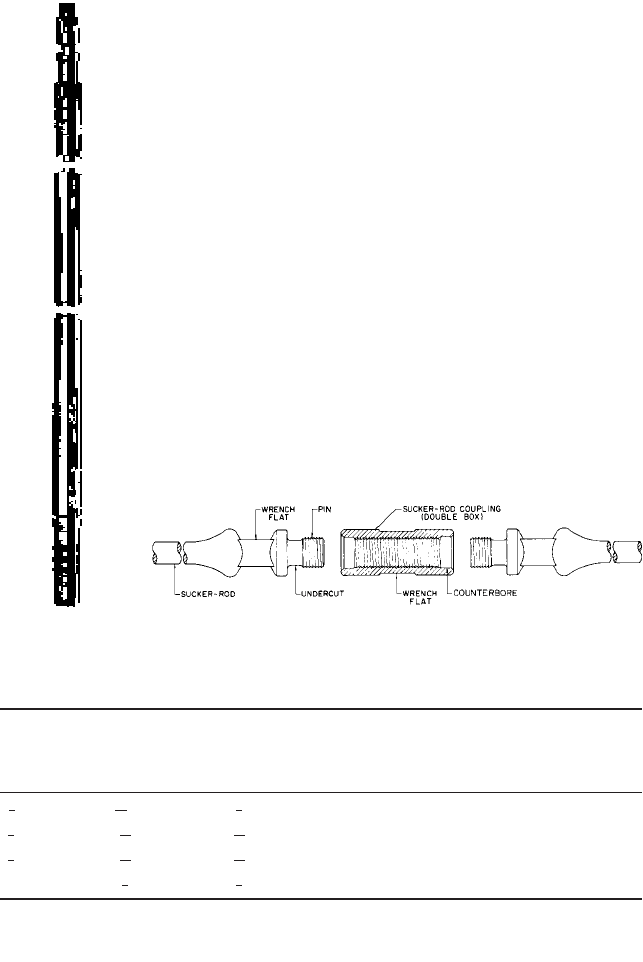
Sucker Rods Sucker rods are manufactured from carbon or low-alloy steel.Table 1 lists
the properties of the grades of rod used most frequently. Most sucker rods are manufac-
tured in 25-ft (7.62-m) lengths, but a few areas use 30-ft (9.14-m) lengths. Both ends of
the rods are upset* and externally threaded (Figure 4). The upset ends also have a square
for wrenching. Internally threaded couplings are used for connecting rods to make the
9.17 OIL WELLS 9.379
FIGURE 1 Sucker rod pumping system: (1) prime mover, (2) gear reducer (3) crank and counterweight,
(4) pitman, (5) walking beam, (6) horsehead, (7) bridle, (8) Samson post, (9) carrier bar, (10) polished rod clamp,
(11) polished rod, (12) stuffing box, (13) pumping tee, (14) tubing ring, (15) casing head, (16) casing surface string,
(17) tubing string, (18) sucker rod, (19) pump barrel, (20) pump plunger, (21) traveling valve, (22) standing valve,
(23) mosquito bill, (24) gas anchor, (25) casing oil string, (26) fluid level, (27) casing perforations (National Supply)
9.380 CHAPTER NINE
FIGURE 2 Operation of a tubing pump
TABLE 1 Mechanical properties of sucker rods
API AISI Yield point, 1000 Tensile strength, Brinell
class steel lb/in
2
(MPa) 1000 lb/in
2
(MPa) hardness Heat treatment
C 1036 60
—
75 (414
—
517) 90
—
105 (621
—
724) 190
—
205 Normalized
M 4621 68
—
80 (469
—
552) 85
—
100 (586
—
689) 175
—
207 Normalized
and tempered
D 4142 100
—
115 (689
—
793) 115
—
140 (793
—
965) 240
—
280 Normalized
and tempered
9.17 OIL WELLS 9.381
FIGURE 3 Sucker
rod pump
FIGURE 4 A typical sucker rod joint (API)
TABLE 2 Sucker rod data
Cross-
Coupling OD, sectional Dry weight, Stretch
Rod size, in Pin size, in in area, in
2
lb/ft factor C,
(mm) (mm) (mm) (mm
2
) (kg/m) USCS
a
(SI)
b
(15.88) (23.81) 1 (41.28) 0.307 (198) 1.15 (1.71) 1.322 (24.76)
(19.05) 1 (26.99) 1 (46.04) 0.442 (285) 1.63 (2.43) 0.919 (17.21)
(22.22) 1 (30.16) 2 (55.66) 0.601 (388) 2.18 (3.25) 0.676 (12.66)
1 (25.40) 1 (34.92) 2 (60.32) 0.785 (507) 2.94 (4.38) 0.517 (9.68)
a
in/1000 ft 1000 lb load
b
mm/km kN load
3
8
3
8
3
16
3
16
7
8
13
16
1
16
3
4
5
8
15
16
5
8
sucker rod string. Maximum design stress for sucker rods is between 30,000 and 40,000
lb/in
2
(207 and 276 MPa), depending on the metallurgy of the rod and the corrosive envi-
ronment of the well. Useful data for designing sucker rod strings are shown in Table 2.

9.382 CHAPTER NINE
TABLE 3 Maximum rating of standard pumping units
Stroke length, Structure capacity,
Torque, in lb (N m) in (m) lb (kN) Design spm
a
6,400 (8,677) 16 (0.406) 3,200 (14.23) 25
10,000 (13,560) 20 (0.508) 4,000 (17.79) 25
16,000 (21,690) 24 (0.610) 5,300 (23.58) 25
25,000 (33,800) 30 (0.762) 6,700 (29.80) 24
40,000 (54,230) 36 (0.914) 8,900 (39.59) 22
57,000 (77,280) 42 (1.07) 10,900 (48.49) 20
80,000 (108,400) 48 (1.22) 13,300 (59.16) 19
114,000 (154,600) 54 (1.37) 16,900 (75.17) 18
160,000 (216,900) 64 (1.63) 20,000 (88.96) 17
228,000 (309,000) 74 (1.88) 24,600 (109.4) 15
320,000 (433,900) 120 (3.05) 25,600 (113.9) 12
456,000 (618,300) 144 (3.66) 30,400 (135.2) 11
640,000 (867,700) 168 (4.27) 35,600 (158.4) 10
912,000 (1,237,000) 192 (4.88) 42,700 (189.9) 9
a
Design spm (strokes per minute) is based on a Mills impulse load of 0.25 with a max-
imum spm of 25. This cycle rate may be exceeded; however, the values given here are con-
sidered good design practice.
*When the sucker rod string is made up of several shorter strings,each of a different diameter, the total string is called
tapered because the smallest-diameter strings are at the bottom and the largest at the top.This is done to reduce the total
weight and to maintain approximately the same stress levels top to bottom.
Design of a single-size string for use in wells of shallow to moderate depth is a straight-
forward calculation and the tables and formulas included here are sufficient. In deeper
wells, tapered* strings of rods are used, frequently 1, , and in (25.4, 22.2, and 19.0 mm).
Various methods are used for calculating the proper taper, but so many variables are
involved that computer programs are frequently used to provide the total system design.
Surface Pumping Units Rating standards of beam pumping units have been estab-
lished by the American Petroleum Institute (API).There are fourteen gear reducer torque
ratings established, and these can be combined with various structures and a variety of
stroke lengths to supply a pumping unit matched to virtually any well condition. Table 3
shows these torque ratings, the maximum stroke length, and the maximum structure
capacity of standard units.
Pumping Installation Calculations The pump bore (ID of the pump barrel) is selected
based on the quantity of fluid to be produced. A trial calculation is made to select a pump
bore and a pumping unit stroke length that will produce the required volume of fluid. A
volume calculation at 100% efficiency is performed using the bore factor from Table 4 and
the stroke length and design strokes-per-minute value shown in Table 3. This is multi-
plied by 0.7 to correct for anticipated pump efficiency under average well conditions.
WEIGHT OF FLUID ON PLUNGER The trial calculation continues with the weight of the fluid
on the plunger. Freshwater exerts a pressure of 0.433 lb/in
2
per vertical foot (9.79 kPa per
vertical meter). The weight of the fluid on the plunger can be calculated with the formula
in USCS units
in SI units W
f
0.00979 A
p
D1sp. gr.2
W
f
0.433 A
p
D1sp. gr.2
3
4
7
8

9.17 OIL WELLS 9.383
TABLE 4 Sucker rod pump data
Pump bore, in (mm) Plunger area, in
2
(mm
2
) Bore factor, USCS
a
(SI)
b
1 (26.99) 0.887 (572.1) 0.132 (0.826)
1 (31.75) 1.227 (791.7) 0.182 (1.139)
1 (38.10) 1.767 (1140.) 0.262 (1.639)
1 (44.45) 2.405 (1552.) 0.357 (2.234)
2 (50.80) 3.142 (2027.) 0.466 (2.917)
2 (57.15) 3.976 (2565.) 0.590 (3.691)
2 (63.50) 4.909 (3167.) 0.728 (4.555)
2 (69.85) 5.940 (3832.) 0.881 (5.512)
3 (82.55) 8.296 (5352.) 1.231 (7.702)
3 (95.75) 11.045 (7126.) 1.639 (10.255)
a
Bore factor stroke length in inches spm barrels/day (42-gal oil barrels).
b
Bore factor stroke length in meters spm cubic meters/day.
3
4
1
4
3
4
1
2
1
4
3
4
1
2
1
4
1
16
°In oil field terminology, a stroke is defined as the complete up and down cycle of the plunger. Distance traveled in one
direction is stroke length.
where W
f
weight (force) of fluid on plunger, lb (N)
A
p
area of plunger (Table 4), in
2
(mm
2
)
D fluid lift, distance from fluid level while pump is operating to ground sur-
face, ft (m)
sp. gr. specific gravity of fluid pumped, ratio of density of fluid to density of water
at 60°F (16°C)
WET WEIGHT OF RODS
The next calculation is the weight of the rods. The dry weight (force)
of the rods Wr in pounds is computed by multiplying the weight (force) per foot of the rods
(Table 2) by the length of the rods. This weight (force) in newtons is kilograms per meter
times the acceleration of gravity (9.807 m/s
2
) times the length of the rod. Because the rods
have buoyancy when immersed in a fluid, their wet weight (force) W
w
can be calculated
with the formula
DEAD WEIGHT OF RODS AND FLUID
This value is needed in subsequent calculations. It is the
weight (force) of fluid on the plunger plus the wet weight of the rods:
IMPULSE LOAD The acceleration due to the reciprocating motion of the rods causes addi-
tional stresses in the sucker rod string. Twice during each stroke,° the rods are stopped
and their motion reversed as they follow a sinusoidal acceleration pattern provided by the
pumping unit. The resulting impulse load can be approximated using the Mills impulse
load formula:
in USCS units
in SI units I
L 1spm2
2
W
r
1780
I
L 1spm2
2
W
r
70,000
W
df
W
f
W
w
W
w
W
r
11 0.128 sp. gr.2

9.384 CHAPTER NINE
where I impulse load, lb (N)
L length of polished rod stroke, in (m)
spm strokes per minute
W
r
dry weight (force) of rods, lb (N)
PEAK POLISHED ROD LOAD The peak polished rod load P is
This peak polished rod load is used in final sizing of the surface pumping unit. If a sin-
gle size of rod is used, P divided by the cross-sectional area of the rod gives the maximum
rod stress. In a tapered string of reds, P divided by the cross-sectional area of the top rod
will also approximate the maximum rod stress unless the rod string design is such that
the rod under maximum stress is not at the top but lower in the string.
MINIMUM POLISHED ROD LOAD
In addition to the peak polished rod load, a minimum pol-
ished rod load is also needed to determine the peak torque on the gearbox of the surface
pumping unit. The minimum polished rod load P
m
is
LOAD RANGE Load range P
r
is
PEAK TORQUE The work transmitted from the prime mover through the gear reducer and
crank applies a torque to the gears. Gear reducers are rated by the peak torque they can
carry on a continuous basis. The peak torque T in inch-pounds (newton-meters) is pro-
portional to the load range and may be calculated from the formula
The calculated peak torque must be lower than the torque rating, and the calculated
peak polished rod load must be lower than the structure capacity rating of the unit
selected (Table 3).
POLISHED ROD POWER The polished rod power P
pr
in horsepower (kilowatts) can be calcu-
lated from the formula
in USCS
in SI units
Because the polished rod power calculation does not take friction into account, the
prime mover selected should have at least double the power of the calculated figure.
PLUNGER OVERTRAVEL In accurately calculating pump displacement, it is necessary to cal-
culate the actual plunger stroke, which is not the same as the polished rod stroke. The
plunger gains stroke from overtravel. Long strings of rods are elastic and capable of
stretching several feet. When the pumping unit stops the polished rod at the bottom of
the surface stroke, the plunger continues to move downward because of inertia. This
plunger overtravel OT in inches (meters) can be calculated from the formula
P
pr
L 1spm2
2
P
r
113,600
P
pr
L 1spm2
2
P
r
750,000
T 0.25P
r
L
P
r
P P
m
P
m
W
df
I
P W
df
I