Pump Handbook by Igor J. Karassik, Joseph P. Messina, Paul Cooper, Charles C. Heald - 3rd edition
Подождите немного. Документ загружается.

2.3.1 CENTRIFUGAL PUMPS: GENERAL PERFORMANCE CHARACTERISTICS 2.375
FLOW RATE, % OF NORMAL
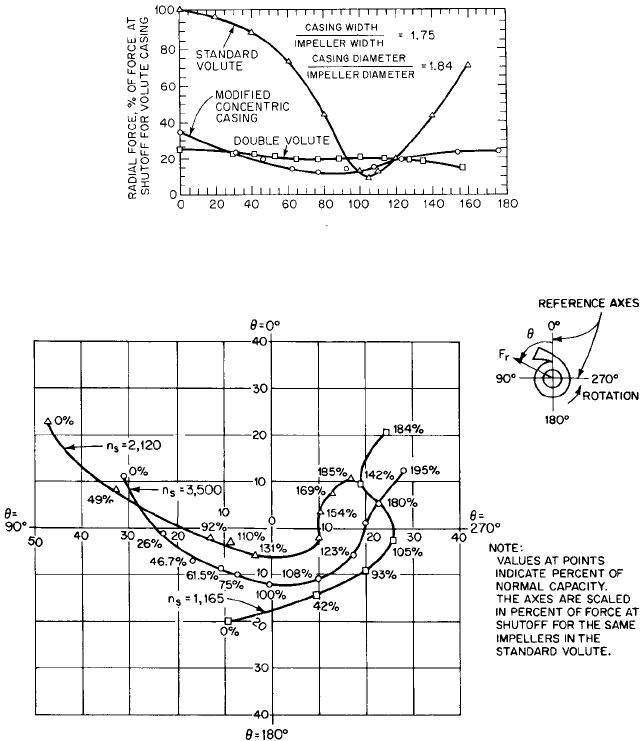
FIGURE 50 Comparison of effect of three casing designs on radial forces for n
s
= 3500 (1.281) (Reference 55)
FIGURE 51 Polar plot showing direction of resultant radial forces for modified concentric casings at various flow
rates and specific speeds; namely, 1,165 (0.426), 2,120 (0.776), and 3500 (1.281). The casings were concentric for
270º from the tongue. (Reference 55)
Solution
(a)
Estimating between the curves for n
S
, 2370 (0.867) and 1735 (0.635) in Figure 47,
the direction of F
r
on the shaft should be about 65° to 70° from the casing tongue in the
direction of rotation.
(b) Use Figure 49, n
s
2120 (0.776), which is nearest to n
s
2000 (0.730), to find
the radial force for a modified concentric casing at half flow, which is about 33%
F
r
10.433210.2211.0212442115.125212.52 799 lb 13554 N2
K
r
0.2 from Figure 46, by Eq. 34.
2.376 CHAPTER TWO
of shutoff value for a single-volute casing. From Figure 46, for a single-volute
casing at shutoff, K
r
0.34 and
Then, for a modified concentric casing at half flow,
From Figure 51, the direction of F
r
should be about 75° to 80° from the casing
tongue in the direction of rotation.
(c) From Figure 49, the radial force for a double-volute casing is about 8% of the
shutoff value for the single-volute casing, and so
According to Agostinelli et al.,
55
the direction of the radial thrust in double-volute casings
was found to be generally toward the casing tongue. Stepanoff
12
has found this direction to
follow approximately that in single-volute casings (see also Biheller
56
).
Axial Thrust See Section 2.1 and 2.2.1.
ABNORMAL OPERATION ______________________________________________
Complete Pump Characteristics
Many types of abnormal operation involve reversed
pump rotation, reversed flow direction, or both, and special tests are required to cover
these modes of operation. Several methods of organizing the data have been proposed, and
each has certain advantages. The Thoma diagrams shown in Figures 52 and 53
45
are eas-
ily understood and are truly complete characteristics diagrams because all possible modes
of operation are covered (see also Reference 57).
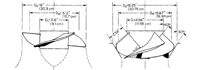
Figure 54 shows schematic cross-sections of the two pumps tested by Swanson
58
for
which characteristics are given in Figure 53.
The Karman circle diagram (Reference 59) attempted to show the complete character-
istics as a four-quadrant contour plot of surfaces representing head and torque with speed
and flow rate as base coordinates. Because the head and torque tend to infinity in two
zones of operation, another diagram would be required to show the complete pump char-
acteristics. The data presented in such a diagram are, nevertheless, adequate for almost
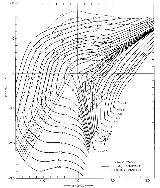
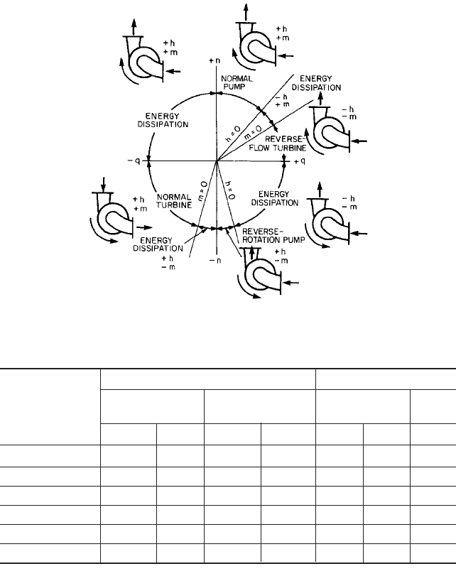
all requirements. One example of a circle diagram is given in Figures 55 and 56. Other
examples may be found in References 12, 58, and 59.
Frequently, tests with negative head and torque have been omitted so that only half of
the usual circle diagram could be shown. This has been called a three-quadrant plot, but
the information necessary to predict an event, such as possible water-column separation
following a power failure, is lacking.
Power Failure Transient A sudden power failure that leaves a pump and driver run-
ning free may cause serious damage to the system. Except for rare cases where a flywheel
is provided, the pump and driver usually have a rather small moment of inertia, and so
the pump will slow down rapidly. Unless the pipeline is very short, the inertia of the liq-
uid will maintain a strong forward flow while the decelerating pump acts as a throttle
valve.The pressure in the discharge line falls rapidly and, under some circumstances, may
go below atmospheric pressure, both at the pump discharge and at any points of high ele-
vation along the pipeline. The minimum pressure head which occurs during this phase of
the motion is called the downsurge, and it may be low enough to cause vaporization fol-
lowed by complete separation of the liquid column. Pipelines have collapsed under the
external atmospheric pressure during separation. When the liquid columns rejoin, fol-
lowing separation, the shock pressures may be sufficient to rupture the pipe or the pump
F
r
, 10.082114032 112 lb 1499 N2
F
r
10.332114032 463 lb 12059 N2
F
r
10.433210.34211.0212522115.125212.52 1403 lb 16241 N2
2.3.1 CENTRIFUGAL PUMPS: GENERAL PERFORMANCE CHARACTERISTICS 2.377
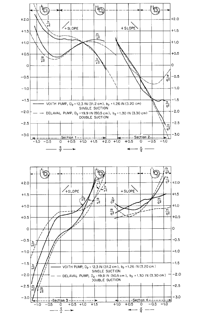
FIGURE 52 Complete pump characteristics. Specific speeds: Voith pump n
s
= 1,935 (0.708); Delaval pump n
s
=
1,500 (0.549). (Reference 45)
2.378 CHAPTER TWO
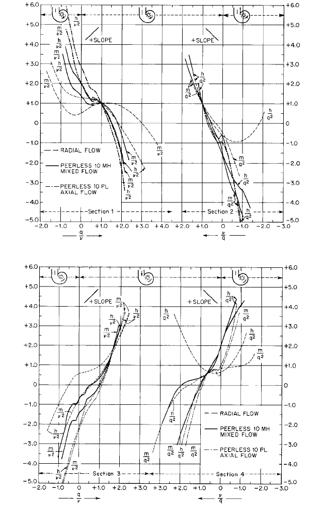
FIGURE 53 Complete pump characteristics. Specific speeds: Radial flow n
s
= 1800 (0.659); Peerless 10MH
mixed flow n
s
= 7,550 (2.763); Peerless 10PL axial flow n
s
= 13,500 (4.940). (Reference 45)
2.3.1 CENTRIFUGAL PUMPS: GENERAL PERFORMANCE CHARACTERISTICS 2.379
FIGURE 54 Schematic cross sections of high-specific-speed pumps. n
s
= 13,500 (4.940) for axial flow pump; n
s
=
7,550 (2.763) (Reference 45)
casing. Closing a valve in the discharge line will only worsen the situation, and so valves
having programmed operation should be closed very little, if at all, before reverse flow
begins.
Reversed flow may be controlled by valves or by arranging to have the discharge pipe
empty while air is admitted at or near the outlet. If reversed flow is not checked, it will
bring the pump to rest and then accelerate it with reversed rotation. Eventually the pump
will run as a turbine at the runaway speed corresponding to the available static head
diminished by the frictional losses in the system. However, while reversed flow is being
established, the reversed speed may reach a value considerably in excess of the steady-
state runaway speed. Maximum reversed speed appears to increase with increasing effi-
ciency and increasing specific speed of the pump. Calculations indicate maximum reversed
speeds more than 150% of normal speed for n
s
1935 (0.708) and h 84.1%
45
. This should
be considered in selecting a driver, particularly if it is a large electric motor.
There will be a pressure increase, called the upsurge, in the discharge pipe during
reversed flow. The maximum upsurge usually occurs a short time before maximum
reversed speed is reached and may cause a pressure as much as 60% or more above nor-
mal at the pump discharge. A further discussion of power-failure transients is given in
Section 8.3.
ANALYSIS OF TRANSIENT OPERATION
The data of Figures 52 and 53 have been presented in
a form suitable for general application to pumps having approximately the same specific
speeds as those tested. The symbols are h H/H
n
,q Q/Q
n
, m M/M
n
, and n n/n
n
,
wherein H, Q, M, and n represent instantaneous values of head, flow rate, torque, and
speed respectively and the subscript n refers to the values at best efficiency for normal
constant-speed pump operation. Any consistent system of units may be used. According
to the affinity laws (Eqs. 12), q is proportional to n, and h and m are proportional to n
2
.
Thus the affinity laws are incorporated in the scales of the diagrams. Figures 52 and 53
are divided into sections for convenience in reading data from the curves. The curves of
sections 1 and 3 extend to infinity as q/n increases without limit in either the positive or
negative direction. This difficulty is eliminated by sections 2 and 4, where the curves are
plotted against n/q, which is zero when q/n becomes infinite.
Usually any case of transient operation would begin at or near the point q/n n/q 1,
which appears in both sections 1 and 2 of Figures 52 and 53.The detailed analysis of tran-
sient behavior is beyond the scope of this treatise. An analytical solution by the rigid col-
umn method, in which the liquid is assumed to be a rigid body, is given in Reference 45.
Friction is easily included, and the results are satisfactory for many cases. The same ref-
erence includes a semigraphical solution to allow for elastic waves in the liquid, but fric-
tion must be neglected. Graphical solutions including both elastic waves and friction are
discussed in References 45 to 48. Computer solutions of a variety of transient problems are
discussed in Reference 47. These offer considerable flexibility in the analysis once the nec-
essary programs have been prepared.
2.380 CHAPTER TWO
FIGURE 55 Circle diagram of pump characteristics. Specific speed n
s
= 4200 (1.537). (Courtesy Combustion
Engineering)
Some extreme conditions of abnormal operation can be estimated at points where the
curves of Figures 52 and 53 cross the zero axes and are listed in Table 9. The data for
Columns 2 to 4 of Table 9 were read from Sections 2 of Figures 52 and 53, and the data for
Columns 6 and 7 were read from Sections 3. Column 8 was computed from Column 7 by
assuming h 1. Let the pump having n
s
1500 (0.549) deliver cold water with normal
head H
n
100 ft (30.48 m), and let the center of the discharge flange be 4 ft (1.2 m) above
the free surface in the supply sump. The discharge pressure head following power failure
may be estimated by assuming the inertia of the rotating elements to be negligible rela-
tive to the inertia of the liquid in the pipeline. Then q 1 and, from Column 2 of Table 9,
the downsurge pressure head is (
—
0.22)(100) 4
—
26 ft (
—
7.9 m), which is not low enough
to cause separation of the water column.
2.3.1 CENTRIFUGAL PUMPS: GENERAL PERFORMANCE CHARACTERISTICS 2.381
FIGURE 56 Explanatory diagram for Figure 55
TABLE 9 Abnormal operating conditions of several pumps
Downsurge Runaway turbine
Free-running Locked-rotor
Specific speed
m/q
2
0 n/q 0 m/n
2
0 h 1
n
s
(
s
) h/q
2
n/q h/q
2
m/q
2
q/n h/n
2
n
12345678
1500 (0.549)
a
0.22 0.36 0.55 0.53 0.46 0.77 1.14
1800 (0.659) 0.24 0.31 0.60 0.44 0.56 0.75 1.16
1935 (0.708) 0.36 0.32 0.94 0.60 0.41 0.66 1.23
7550 (2.763) 0.23 0.56 1.57 1.38 0.99 0.38 1.62
13,500 (4.940) 0.12 0.67 0.96 0.60 1.08 0.33 1.73
a
Double-suction.
Actually the downsurge would be less than this because of the effects of inertia and fric-
tion, which have been neglected. If this pump were stopped suddenly by a shaft seizure or
by an obstruction fouling the impeller, Column 4 of Table 9 shows the downsurge to be
(
—
0.55)(100) 4
—
59 feet (
—
18 m), which would cause water column separation and, prob-
ably, subsequent water hammer. If, following power failure, the pump were allowed to oper-
ate as a no-load turbine under the full normal pump head, Column 8 of Table 9 shows the
runaway speed would be 1.14 times the normal pump speed. The steady-state runaway
speed usually would be less than this because the effective head would be decreased by
friction, but higher speeds would be reached during the transient preceding steady-state
operation. Column 8 shows that runaway speeds increase with increasing specific speed.
2.382 CHAPTER TWO
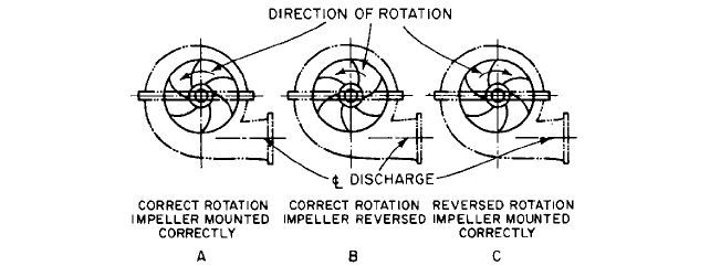
FIGURE 57A through C Pump assembly and rotation (Reference 7)
Incorrect Rotation Correct rotation of the driver should be verified before it is coupled
to the pump (Figure 57). Sections 3 of Figures 52 and 53 show that reversed rotation might
produce some positive head and flow rate with pumps of low specific speed, but at very
low efficiency. It is unlikely that positive head would be produced by reversed rotation of
a high-specific-speed pump.
Reversed Impeller Some double-suction impellers can be mounted reversed on the
shaft. If the impeller is accidentally reversed, as at B in Figure 57, the flow rate and effi-
ciency probably will be much reduced and the power consumption increased. Care should
be taken to prevent this, as the error might go undetected in some cases until the driver
was damaged by overload. Table 1 shows performance data for six pumps with reversed
impellers. At least one of these would overload the driver excessively.
Further discussion of abnormal operating conditions may be found in References 7, 12,
and 34.
Vibration Vibration caused by flow through wearing rings and by cavitation has been
discussed in the foregoing and some remedies indicated. Vibration due to unbalance is not
usually serious in horizontal units but may be of major importance in long vertical units,
where the discharge column is supported at only one or two points. The structural vibra-
tions may be quite complicated and involve both natural frequencies and higher har-
monics.Vibration problems in vertical units should be anticipated during the design stage.
If vibration is encountered in existing units, the following steps may help to reduce it: (1)
dynamically balance all rotating elements of both pump and motor; (2) increase the rigid-
ity of the main support and of the connection between the motor and the discharge col-
umn: (3) change the stiffness of the discharge column to raise or lower natural frequencies
as required. A portable vibration analyzer may be helpful in this undertaking. Kovats
60
has discussed the analysis of this problem in some detail.
Structural vibrations can occur in most pump types. Typical sources are a) bearing
housings
—
due to the commonly encountered cantilever construction, b) couplings, c) rotor
instabilities stemming from excessive ring clearances and consequent loss of Lomakin
stiffening of long-shaft multistage pumps, and d) hydraulic unbalance
—
due to dimen-
sional variations in flow passages and clearances
61
.
PREDICTION OF EFFICIENCY FROM MODEL TESTS _______________________
Many pumps used in pumped storage power plants and water supply projects are so large
and expensive that extensive use is made of small models to determine the best design. It
is often necessary to estimate the efficiency of a prototype pump, as a part of the guaran-

2.3.1 CENTRIFUGAL PUMPS: GENERAL PERFORMANCE CHARACTERISTICS 2.383
tee, from the performance of a geometrically similar model. A model and prototype are said
to operate under dynamically similar conditions when
where D impeller diameter
n pump speed
H pump head
in any consistent units of measure. Primed quantities refer to the model and unprimed
quantities to the prototype. Dynamic similarity is a prerequisite to model-prototype test-
ing so that losses that are proportional to the squares of fluid velocities, called kinetic
losses, will scale directly with size and not change the efficiency. Surface frictional losses
are boundary-layer phenomena which depend on Reynolds number
where n kinematic viscosity of the liquid pumped.
(See also Section 2.1, Eqs. 36
—
40.) Reynolds numbers increase with increasing size, and,
within limits, surface frictional-loss coefficients decrease with increasing Reynolds num-
ber. This leads to a gain in efficiency with increasing size. Computational difficulties have
forced an empirical approach to the problem. Details of the development of a number of
formulas are given in Reference 62.
Moody-Staufer Formula In 1925, L. F. Moody and F. Staufer independently developed
a formula that was later modified by Pantell to the form
(35)
where h
h
hydraulic efficiency, discussed previously, and D impeller diameter. Primed
quantities refer to the model, and n is a constant to be determined by tests. The model
must be tested with the same liquid that will be used in the prototype; that is, cold water
in most practical cases.The original formula contained a correction for head, which is neg-
ligible if H¿ 0.8H, and this requirement is now virtually mandatory in commercial prac-
tice. The meager information available indicates 0.2 n 0.1 approximately, with the
higher value currently favored. Improvements in construction and testing techniques very
likely will move n toward lower value in the future. The Moody-Staufer formula has been
widely used since first publication. In practice, both h¿
h
and h
h
are usually replaced by the
overall efficiencies h¿ and h, respectively, because of the difficulty in determining proper
values for the mechanical and volumetric efficiencies (see Eq. 11).
Rütschi Formulas The general form of several empirical formulas due to K. Rütschi
62
and others was originally given as
(36)
where h
h
and h¿
h
are the hydraulic efficiencies of the prototype and model, respectively, and
f and f ¿ are values of an empirical f function for both the prototype and the model. The f
function was obtained from tests of six single-stage pumps. n
S
2000 (0.732) and is shown
in Figure 58 based on the eye diameters D
o
of the pumps in millimeters. Thus the f func-
tion depends on actual size in addition to scale ratio.The extrapolated portion of the curve,
shown dashed in Figure 58, checked well with values for a model and large prototype,
shown by E¿ and E, respectively. One of several formulas that have been proposed to fit the
curve in Figure 58 is, in SI units,
(37)f 1
3.15
D
o
1.6
h
h
f
f¿
h¿
h
a
1 h
h
1 h¿
h
b a
h¿
h
h
h
b a
D¿
D
b
n
Re D2H>n,
Dn>2H
D¿n¿>2H¿,
2.384 CHAPTER TWO
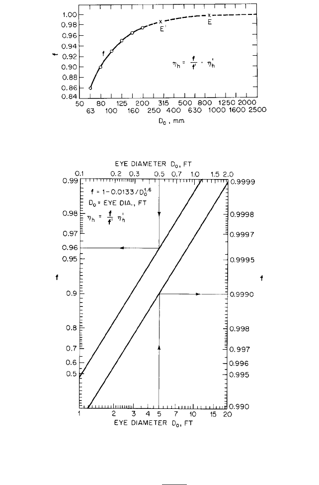
FIGURE 58 The f function for the Rütschi formula (to obtain D
o
in inches, multiply by 0.03937) (References 13
and 62)
FIGURE 59 Chart for the solution of the Rütschi formula (to obtain D
o
in meters, multiply by 0.3048)
(Reference 62)
where the eye diameter D
o
is in centimeters or, in USCS units,
(38)
where D
o
is in feet. Figure 59 gives a graphical solution of Eq. 38. The Society of German
Engineers (VDI) has adopted a slightly modified version of the Rütschi formula as stan-
dard. Rütschi later recommended, in discussion of Reference 62, that the internal effi-
f 1
0.0133
D
o
1.6