Pump Handbook by Igor J. Karassik, Joseph P. Messina, Paul Cooper, Charles C. Heald - 3rd edition
Подождите немного. Документ загружается.


5.1 METALLIC MATERIALS OF PUMP CONSTRUCTION 5.15
Environment Materials Hardness
Non-corrosive Cast iron/leaded bronze Unimportant
Mildly Martensitic stainless steels (locally or Less than 45
corrosive through hardened) R
c,
10-point differential
Greater than 45 R
c
, same
hardness acceptable
Corrosive Corrosion-resistant, non-galling Not applicable
austenitic stainless steel (Nitronic
50/Nitronic 60 or Waukesha 88/
Nitronic 50)
Severely Highly alloyed austenitic stainless
corrosive seel with hard-faced materials
such as Stellite or Colmonoy Not applicable
• Corrosiveness of the fluid
• Amount of wear allowed
• Galling stress
Corrosion determines the class of material to be used. These classes generally fall into
three groupings: non-corrosive, mildly corrosive, and corrosive. Of course, additional con-
straints occur when selecting an appropriate material within the corrosive material
grouping that will need to be addressed by application experience.
Other material characteristics, such as additives, can significantly affect performance
with regard to adhesive wear and galling. For example, copper alloys with lead additions
are considered to be bearing alloys because of the capability of the lead to provide lubric-
ity between contacting surfaces. Alternatives are being evaluated today to replace leaded
bronze alloys to avoid the health considerations of lead usage. This is also true of tin and
bismuth additions to nickel-based alloys.
A general guide for materials in several environments is as follows:
Using these industry-wide accepted rules of thumb will help avoid catastrophic dam-
age normally resulting in costly repairs.
Some special applications have produced unique material applications for given envi-
ronments.These include low specific gravity applications where the use of mechanical car-
bon materials is desirable because of the non-lubricating nature of these fluids. Common
practice is to make the stationary component metal-filled graphite if the specific gravity
is 0.5 or less. Stationary mechanical carbon components are also used in liquid CO
2
ser-
vices and other potential dry start applications, such as the upper bearing in vertical
pumps. Currently, non-metallic wear components, such as advanced polymers and ceram-
ics, are being looked at to solve nagging problems encountered in a variety of applications.
Usually, these are glass-filled polymers or ceramic composites with various additives to
enhance their wear resistance.
Fretting Fretting can be considered a special case of adhesive wear. It occurs when two
parts in contact experience a repeated, small amplitude relative motion between close-
fitting surfaces such as a loose impeller on a shaft. Researchers have described fretting
damage as a four-stage event:
2
1. Adhesive wear of the asperities on the mating materials
2. Abrasive wear caused by the wear debris produced in step one
3. Abraded particles filling the asperity valleys
4. Elastic contact producing cold working of the surface and micro-pitting
5.16 CHAPTER FIVE
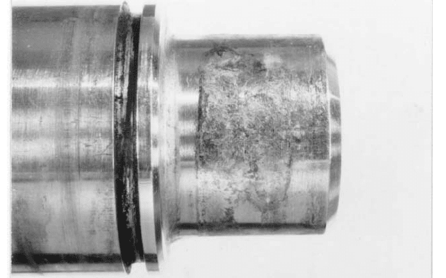
FIGURE 8 The fretting damage of a shaft beneath an impeller that experienced small amplitude motion. The
mottled appearance is typical of the damage caused by fretting (2.2).
In a pump, there is the potential for small amplitude motion at loose fitting impellers,
beneath loose bearings, and between impeller wear rings and the impeller hub.The design
engineer does not intentionally create a circumstance that will generate this type of
motion, but when it occurs, fretting damage can lead to other problems.
Fretting can be identified by a red powdery oxide that forms along the fretted surface.
In a pump, the red-colored debris is often washed away, but a distinct damaged surface
appearance will develop on the fretted surfaces. This damage is often described as having
a mottled appearance and is best depicted as a flat, eroded surface with no directionality
to the damage. Although the oxide may be washed from the surface, some staining of the
adjacent component can be observed after disassembly of the pump. This has led to the
misinterpretation that fretting is a corrosion mechanism, but it is actually a special wear
phenomenon.
Figure 8 shows the fretting damage of a pump shaft along the impeller-fitted area
where a loose fit enables the oscillation of the impeller during operation. Since the motion
necessary to cause fretting can be of a small amplitude, large vibrations in the pump may
not be present. This makes the detection of fretting during any operation impossible. The
impeller in this example would have similar damage along its bore.
Fretting damage can be avoided with a few relatively simple guidelines. You should
eliminate or prevent the possibility of motion between the two components by either
tighter clearances, or shrink fitting the assembly, which increases the clamping force. If
fretting is unavoidable in a particular design, methods of mitigation can be used. These
include various coatings or providing the contact zone with an appropriate lubricant. Coat-
ings that may be used include flame-sprayed high-nickel alloys, silver plating, or possibly
adding a thin, dense chrome plating to one or both of the faces in contact.
Abrasive Wear Abrasive wear is often categorized into two main classifications: two-
body and three-body wear. The name indicates the mechanism of wear. For the most part,
three-body abrasive wear is the primary mechanism of damage in centrifugal pumps. This
can occur when hard solid particles entrained in the fluid enter between ring fit areas or
impeller keyway faces. In fluids with high concentrations of solids, another form of three-
5.1 METALLIC MATERIALS OF PUMP CONSTRUCTION 5.17
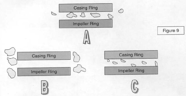
FIGURE 9 Three possible conditions between wear surface clearances and solid particle size. Condition “A” is
conducive to maximum three-body abrasive wear.
body wear is produced. Solids carried in the fluid stream can strike the internal pump
surfaces. This is more commonly referred to as erosion. This type of damage is observed
in the impeller and cutwaters of the casing. The degree of material damage, due to this
mechanism, depends upon the bulk hardness of the material, the carbon content, and the
characteristics of the solids present. Important particle characteristics include size, shape,
hardness, and mass.
To minimize three-body abrasive wear, a couple of variables must be taken into con-
sideration. The wear ring clearance influences damage. The relationship between the size
of the particles in the fluid stream and the gap into which they can enter is important.
This is graphically illustrated in Figure 9, which shows three types of particle-to-gap rela-
tionships. Condition A is logically the most damaging three-body abrasive case.A high rate
of damage will result as these particles are entrapped between the two components. In
condition B, large particles relative to the ring clearance will not enter and produce dam-
age. This condition enables the particles to flow with the fluid stream through the eye of
the impeller and exit the pump. In condition C, very fine or relatively small particles will
not be entrapped and ground between the rings and will not result in collateral damage of
the components.
For the most part, particles in a fluid service will be in a range of sizes, so all the con-
ditions will exist. Typically, a particle size and distribution analysis is performed to char-
acterize the amount of particles that will cause condition A to exist. This is relatively
simple to accomplish by extracting the solids from a fluid sample and performing a sieve
analysis. The percentage of solids present in the fluid stream is extremely important for
determining the appropriate material and design considerations. This will be addressed
later with guidelines given for appropriate material selections.
Wear particle hardness is also extremely important. If particles are soft and friable,
such as talc, little damage would be expected to occur on metal pump components because
of three-body abrasive wear. The amount of damage is expected to be greater if the parti-
cles are extremely hard. These particles include welding scale or silicon dioxide (SiO
2
),
which is sand. The particle geometry also contributes to the amount of damage that can
result in three-body abrasive wear. Often, particles of SiO
2
are found in a rounded condi-
tion. Pumps used to handle river water or seawater on ships frequently encounter these
configurations. Hard, round particles are less damaging than particles of equal hardness
with sharp, angular configurations. Fly ash, a very hard, sharp, angular particle, is one of
the most abrasive services encountered in the pump industry.
5.18 CHAPTER FIVE
A material’s resistance to abrasive wear can be characterized by a standard ASTM test
procedure. Each testing procedure attempts to simulate the mechanism that most appro-
priately addresses the class of abrasive wear. In general, materials that are resistant to
two-body abrasive wear are resistant to three-body abrasive wear also.
Test results show that the primary property responsible for increasing resistance to
abrasive wear is the hardness of a metal alloy. Zum Gahr has provided test results to
graphically illustrate this fact.
3
Small microstructural differences, alloying, and surface-
condition differences within alloy groups also can influence the abrasion resistance of a
material. Some of these conclusions include the following:
• Abrasion resistance is increased with increasing bulk material hardness.
• At the same bulk hardness, steels with higher carbon content have higher abrasion
resistance.
• Cold working, which increases a material’s surface hardness, does not significantly
increase the abrasion resistance of the alloy.
• Precipitation hardening increases the bulk material hardness and abrasion resistance
of an alloy.
• Gray cast irons show a decreasing abrasion resistance at higher hardnesses.
• Softer, austenitic, white cast irons exhibit improved abrasion resistance over marten-
sitic, white cast irons.
• Carbides are important for the wear resistance of steels and chromium-alloyed, white
cast irons.
• A carbide volume fraction of 30% maximizes the abrasive wear resistance for materials
with a soft matrix.
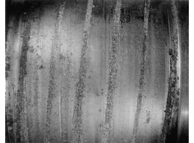
An example of three-body abrasive wear is shown in Figure 10. It shows a laser-hardened
shaft sleeve after approximately one year of service in a mine dewatering operation where
abrasive wear caused a significant wear of other material combinations. The abrasive wear
was caused by fine tailings in this gold mine application. To increase the life of rings in ser-
vices like this, the use of hardened wear rings is a good start. This is the reason why pump
producers use coated rings in applications where significant abrasive wear is anticipated.
However, depending upon the severity of the service, a choice of a ring material containing
carbides may be necessary.
For mildly abrasive services, the following materials should be considered:
• Ni-Resist—Its resistance is due to chromium carbides in the matrix. It has good
adhesive wear resistance also.
• Selectively hardening the surface of AISI 420 (laser hardened 50-55 R
c
). Surface hard-
ening is not susceptible to hydrogen embrittlement or SCC.
• Carburized and hardened 12% chromium stainless steel.
For more abrasive services, the following is often considered:
• Hardened AISI-440C (50–55 R
c
)
• Stellite or colmonoy-coated (hard-faced) austenitic stainless steel
• Solid stellite
• Tungsten carbide
• Silicon carbide
• Partially stabilized zirconia (PSZ)
Recent advances involving the use of ceramics, metal-matrix composite materials,
laser-surface alloying, and laser-surface modifications to a substrate that normally could
not survive in an abrasive service are examples of ongoing material developments.
5.1 METALLIC MATERIALS OF PUMP CONSTRUCTION 5.19
FIGURE 10 The three-body abrasive wear of a laser-hardened shaft sleeve in an abrasive service. Note the fine
concentric scoring of the hardened surface. The helix pattern is the laser-beam overlapped zone produced by the
laser process.
Erosion Most fluids handled by pumps are considered clear liquids, meaning they do
not have significant amounts of solid particulates present. The corrosive nature of these
fluids dictates the required pump materials. Guidelines for many of these services are
embodied in “Corrosion in Pumps,” a tutorial published in the Ninth International Pump
Users Symposium.
4
However, many fluid-handling applications requiring pumps are far from clear liquids.
Solid particulates can be removed with costly filtration systems that must work flawlessly
at all times. Fabricated piping systems may introduce suspended solids from weld slag and
pipe burn. Naturally occurring suspended solids are those found in water sources such as
river water or seawater, as mentioned previously in the abrasive wear section.
The following factors should be considered during the material and pump selection
phase of the procurement process:
• The hardness of the particles
• The quantity of particles
• Size distribution
• Nature (geometry)
• The velocity of the pumpage
• The angle of fluid impingement
The first four items listed deal with the suspended solids. These variables can vary
from application to application. The hardness of the particles is important to understand
in determining the materials necessary to yield an acceptable pump lifespan. Hardness
can range from relatively soft substances, such as cellulose fiber in pulp and paper appli-
cations, to very hard abrasive particles such as silicon or rock in mining pumps. The Miller
5.20 CHAPTER FIVE
number index, as described in ASTM G75,
5
is used to characterize the abrasivity of hard
particles.
The Miller number was developed to determine the relative abrasivity and attrition of
solid particles making up a slurry. In a closed loop test, the abrasivity of the particles
becomes less damaging with time due to the fracturing and rounding (or friability) of the
particles as they strike each other and/or impinge on a pump or casing wall.
The Miller number is therefore reported with two numbers. The first number char-
acterizes the abrasivity of the particles and the second is the loss of abrasivity (attri-
tion) of the particles during the slurry test. The abrasivity portion of the Miller number
is useful in practical applications because this more closely characterizes a slurry’s
damaging potential. The attrition number has found little use other than characterizing
a test loop’s influence on a slurry. A slurry with a Miller number less than 50 is not con-
sidered abrasive in a reciprocating pump. Examples of slurries with a Miller number
below 50 are limestone, sulfur, and detergent. It has been determined that a slurry con-
sisting of finer particles is less abrasive then one containing larger particles. Test data
shows that Corundum at 220 mesh is about four times as abrasive as the same mater-
ial at 400 mesh.
5
Particle velocity plays a major role in the degree of damage that occurs in a pump han-
dling slurries. In this case, the potential energy is converted into kinetic energy, producing
a material loss by the transfer of energy from the particle to the component. The amount
of material damage on an individual particle scale depends specifically upon particle veloc-
ity, v, and mass, m (kinetic energy, defined as mv
2
). This is demonstrated by Finnie’s equa-
tion
6
for hard materials:
Of course, the pump part that absorbs the kinetic energy resulting from the particle
impact has a role to play also. The material hardness and/or resilience of the pump com-
ponent in absorbing the particle’s impact energy will also determine the amount of mate-
rial loss.
Chen and Hu
7
have performed laboratory tests on materials while changing the parti-
cle variables previously described. Their test results show the following:
• An increased particle hardness increases the material loss up to 1700-kg/mm
2
micro-
hardness (greater than 75 R
c
). Beyond this hardness, a decrease in wear occurs. This
is most likely the result of the hard, brittle particle fracturing, which absorbs some of
the kinetic energy.
• Sharp, angular particles increase the erosion rate over round particles.
• Erosion increases with increasing concentrations of abrasive particles.
• An increased fluid (and particle) velocity increases the erosion rate.
• Minimal erosion occurs at an impingement angle of 0° (tangent to the target surface)
and increases to a maximum amount of wear at a 65° angle.
A review of the literature shows that several authors have plotted the solid particle
impingement angle versus the amount of erosion.
8,9
These plots show that for ductile
materials, erosion increases with the increasing impingement angle to a maximum mate-
rial loss at an angle of 25°. Then the erosion damage decreases to the 65° impingement
angle previously mentioned. Brittle materials, such as glass, are quite different. As the
impingement angle increases from 0° to 90°, the volume of material loss continuously
increases.
The characteristic features of erosion damage due to solid particle impingement are
usually recognizable. However, when an aggressive fluid is present, the effects of solid par-
ticle impingement may not be easily identified. These effects can appear very much like
corrosion-erosion, which is a fluid velocity-controlled damage mechanism where entrained
solids are not present. If this damage is misdiagnosed, an improper material substitution
can be made that may not solve the real problem. Conversely, a more likely situation is
Wear rate 1# of impinging particles2 1average particle mass2
1impingement velocity2
2
1angle of impingement2
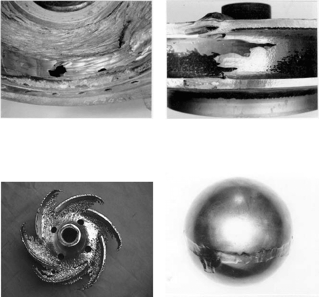
FIGURE 13 An austenitic stainless steel impeller in
an abrasive fly ash service that shows severe erosion.
Increased erosion occurs with an increasing fluid
velocity near the periphery of the impeller.
FIGURE 14 Erosion damage of an AISI-type, 440C
stainless steel ball valve in a coal slurry service
5.1 METALLIC MATERIALS OF PUMP CONSTRUCTION
5.21
FIGURE 11 The severe erosion of a carbon steel
casing in a 17% bauxite and sand service. Note the
gouging due to the local turbulence of the slurry.
FIGURE 12 Erosion at the exit vane tips of a duplex,
stainless steel CD4MCu impeller in a bauxite service.
that the observed damage resulting from the erosion-corrosion is misinterpreted as solid
particle erosion.A full understanding of the pumpage including the fluid velocity, fluid cor-
rosiveness, content, and nature of the solid particles present is necessary for the appro-
priate action to be taken in improving the life of a damaged pump.
An example of solid particle erosion in a pump is shown in Figures 11 and 12. The
severe erosion damage of a casing is illustrated by the gouging of surfaces that were
directly impinged or scoured by glancing blows of the solid particles in the fluid stream.
This pump handles a bauxite slurry where the percentage and velocity of alumina (Al
2
O
3
)
and sand are too high for the carbon steel casing and CD4MCu impeller.
Figure 13 shows a CF3M impeller in a fly ash service. This shows that the greatest
damage to the impeller is at the outer periphery, which corresponds to the highest veloc-
ity of the slurry. The least amount of damage is near the impeller inlet eye. Figure 13 also
shows that the lower velocity region of the impeller inlet eye has the least damage. This
confirms the laboratory data that shows an increased erosion with an increased slurry
velocity. Note that the damage increases near the outside of the inlet eye and is almost
nonexistent at the impeller hub where the fluid velocities are lower.
Erosion damage can also be encountered in reciprocating pumps. Figure 14 shows
extensive erosion of an AISI-type, 440C stainless steel ball from a ball valve after it
5.22 CHAPTER FIVE
became stuck and unable to rotate in a coal slurry application. This caused a slurry
impingement on a concentrated region of the ball.
The particle velocity and impingement angle are design factors that can be used to mit-
igate erosion in pumps.The challenge in the coal liquefaction program investigated by the
Department of Energy in the 1970s was to develop a high-speed pump for handling coal-
oil slurries.
8
This was attempted because traditional slurry pumps are usually large, slow-
moving machines that increased the capital and operating costs of pilot plants built during
that era. Most of the slurry pump industry utilizes large, slow-moving, single-stage pumps
to address the solid particle erosion problem. Many of these pumps are rubber-lined to
absorb the particle’s impingement energy.
Erosion damage, once identified, has a limited number of solutions to prolong the
longevity of pump materials. This can be accomplished by the selection of hard, wear-
resistant replaceable liners, elastomeric liners, or, in cases where liners cannot be utilized,
hard materials. Such metallic materials include white cast iron (such as Ni-Hard), high
chromium (13 to 28 percent) alloy steels, cobalt-based super alloys (such as Stellite), and
nickel-based alloys.
FATIGUE ____________________________________________________________
Centrifugal and reciprocating pumps are subjected to cyclical loading, which, if not con-
sidered during design, will result in a limited life due to material fatigue. In combination
with a corrosive environment, material fatigue can be accelerated due to what is com-
monly referred to as environmentally assisted fatigue.
The one essential parameter in component fatigue is the presence of an alternating or
cyclic load. In general, pumps are machines that have either fluid or mechanically induced
cyclic loading on their components. Although centrifugal pumps are for the most part
steady-state rotational equipment, pulsations or fluctuating applied stresses are encoun-
tered. The source of these cyclic stresses can be from fluid interaction between impeller
exit vanes and diffuser vanes or, in a volute pump, the impeller vanes and the casing cut-
water. Mechanically induced forces are due to bending moments acting on the pump shaft
or possibly a component imbalance in the rotor assembly. Reciprocating pumps experience
a cyclic loading of the internal and external components from the action of the machinery.
In fact, these pumps can be thought of as large fatigue-testing machines due to the pul-
sating action of the pumping process.
When cyclic forces are applied to materials in a pump over a period of time, a crack may
initiate at the component’s surface. After initiation, the crack will grow with continued
cyclic loading until the part finally fractures. Fractures can occur, even though the loading
produces stresses that are far less than the tensile strength of the material. Engineers
have been aware of this potential mode of component fracture for many years and have
developed design criteria that take this anomaly into account. The study of cyclic loading
and material behavior based upon cyclic stress history and flaw size is beyond the scope
of this text. It should be noted, however, that the field of fracture mechanics offers an engi-
neering design tool that can predict the life of an engineered component.
Fatigue is a three-stage process consisting of (1) crack initiation, sometimes associated
with preexisting defects, (2) crack propagation, and (3) the final fracture, associated with
crack instability, as suggested by Wohler.
10
The applied stress level, sample geometry, flaw
size, and mechanical properties determine the existence and extent of these stages.
Fatigue was first studied by August Wohler in 1852.
11
Wohler’s work included the con-
cept of alternating applied stress, S, and the number of cycles, N, applied to a sample until
a fracture occurs. This work is the basis for today’s S/N curves used by design engineers.
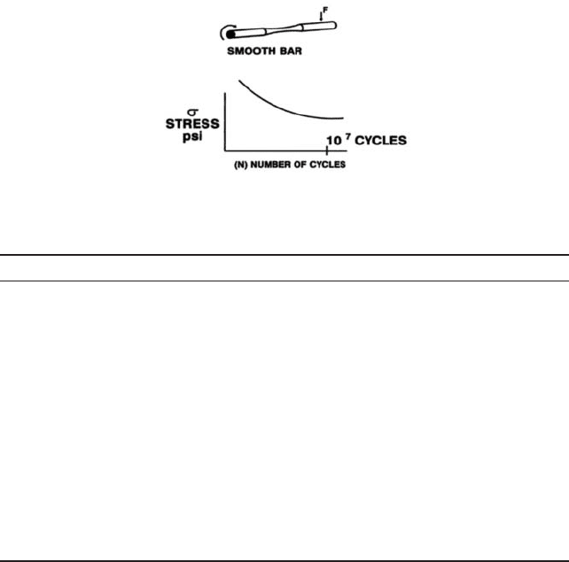
A laboratory-generated S/N curve is shown in Figure 15. This curve was generated by
smooth, rotating-beam test specimens. These specimens are machined carefully to avoid
metallurgical notches on their surfaces that would lower the applied stresses required to
produce a failure during testing.
When a corrosive media is introduced, many crack initiation sites are produced. The
lower curve shows the resulting drop in the endurance limit. Since corrosion over time can
5.1 METALLIC MATERIALS OF PUMP CONSTRUCTION 5.23
FIGURE 15 A laboratory-generated S/N curve for a smooth bar rotating beam test specimen
TABLE 2 Corrosion fatigue strength of alloys in sea water*
Alloy UTS CFS
Ti-6Al-4V 154 88
Inconel 718 189 60
Inconel 625 149 50
Hastelloy C 108 32
Monel alloy K-500 176 26
Ni Al bronze (cast) 115 15
304 Stainless 79 15
316 Stainless 85 14
304L Stainless 75 14
316L Stainless 79 13
17-4PH - cast 10
70-30 Cu-Ni (cast) 83 9
Ni Mn Bronze 82 9
Mn Bronze 73 8
D-2 Ni-Resist 7.5
Mild steel 2
*Test parameters: ambient temperature, 1750 rpm, 2–3 ft/s (0.6–0.9 m/s). Corrosion fatigue
strength (CFS) given at 100,000,000 cycles. All values are in ksi; 1 ksi = 6.894759 mPa. (UTS is ulti-
mate tensile strength of material in air.)
increasingly damage the material, the endurance limit will correspondingly decrease with
the exposure time. No true fatigue limit exists for materials in a corrosive environment.
For this reason, the corrosion-assisted fatigue life of a material is usually published with
cautionary statements. Given enough time, corrosion can penetrate completely through a
fatigue test specimen, resulting in a data point of zero load and zero cycles. For this rea-
son, corrosion-influenced fatigue test results usually specify the corrosive media, the test
temperature, the details of the sample pre-exposure to the corrosive media, and the test
frequency with respect to the applied cyclic loading.
Published data varies because laboratories that use a low frequency of applied stresses
increase the influence that corrosion has upon the test specimens. This is in comparison
to laboratories that conduct these tests at a high frequency that minimizes the influence
of the corrosive media. Published values for the ultimate tensile strength and corrosion
fatigue strength of various alloys are shown in Table 2.
12
Wohler’s investigation shows that a mechanical notch can reduce a material’s fatigue.
10
This is shown in Figure 16 as a shift in the S/N curve below the curve produced by a
smooth bar specimen. The severity of the notch determines the amount of divergence from
the smooth bar curve. As shown, the surface degradation mechanisms lower the stress
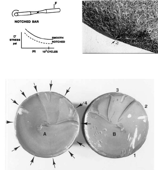
5.24 CHAPTER FIVE
FIGURE 17 SEM photo of a fracture smooth fatigue
test specimen with a single origin. The arrow indicates
the fatigue crack origin.
FIGURE 16 A shift in the S/N curve below the
curve produced by a smooth bar specimen. The
severity of the notch determines the amount of
divergence from the smooth bar curve.
needed to produce the specimen failure after a certain number of cycles. This in turn
reflects a lowering of the material’s endurance limit.
The three stages of fatigue cracking can be observed on the fracture face, rendering
them easily identifiable. This is especially true if no other secondary damage masks the
characteristic appearance. Especially in fractures that occur over long periods, lines are
visible on the fracture surface. These bands are sometimes referred to as clamshell mark-
ings, crack arrest lines, or beach marks and reflect different periods of crack growth.
Ratchet lines, which represent the joining of two different crack fronts on different planes
into one, are observed in multiple origin fatigue cracks. Multiple origin fatigue fractures
are often associated with rotating components.
Figure 17 shows a high magnified view of a smooth bar fatigue specimen after a frac-
ture.The arrow shows a single origin of this specimen.This fatigue crack propagated across
the entire specimen diameter until the final fracture occurred, shown as a small circle.The
final fracture is sometimes referred to as the ductile overload zone or the fast fracture zone.
An example of a fatigue fracture on a pump shaft is shown in Figure 18. The arrows in
this figure indicate the location of many crack origins. The flat, smooth surface appearance
FIGURE 18 Multiple origin fatigue fracture of a pump shaft. The arrows show the locations of the many fatigue
crack origins. A and B correspond to the final fracture zone of each fracture face.