Pump Handbook by Igor J. Karassik, Joseph P. Messina, Paul Cooper, Charles C. Heald - 3rd edition
Подождите немного. Документ загружается.

7.22 CHAPTER SEVEN
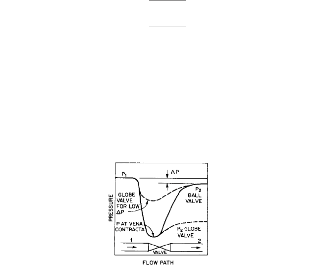
FIGURE 33 For a given pressure drop DP across a valve, the globe will show a higher pressure at the vena
contracta, making it more likely that cavitation difficulties will be avoided when the vapor pressure is high.
change in stem travel. A high gain means that a slight movement of the stem causes a
large change in flow rate, so instability occurs more readily. This sets a limit on a valve’s
rangeability. The quick-opening valve, with a high gain in the nearly closed position, is
unsuitable for many modulating tasks.
Valves with approximately an equal-percentage flow characteristic are considered
most suitable for the majority of flow control tasks; valves with a linear characteristic are
preferred for some applications.
SIZE The size of a valve is an indefinite concept. In the past, a valve’s size was understood
to be the pipe size of the line connected to it. Venturi valves with tapered end passages
leading to reduced-diameter orifices and valves in which the orifice area is reduced for
reasons such as cost-cutting, characterization, and special advantages have forced users
to rate valve size in other terms. A statement of maximum orifice area might be a way to
express size, but this too would be ambiguous because the head losses in partial recovery
after the orifice are not the only losses in the valve. In addition, the valve may have two
or more orifices in series, and the geometry of the orifice itself may affect results.
FLOW COEFFICIENT
The valve flow coefficient C
v
(K
v
in SI units) is now a frequently used
parameter for valve size. It is the number of gallons per minute (cubic meters per hour) of
60°F (15.6°C) water that will flow through a valve at a 1-lb/in
2
(1-bar) pressure drop across
the valve. The upstream test pressure is also stated. The maximum C
v
(K
v
), found with the
valve fully open, is widely accepted as a measure of valve size. To find the maximum liquid
flow rate of a valve at any pressure drop and with a liquid of any specific gravity, the equa-
tion is
in USCS units
in SI units
where Q flow rate, gpm (m
3
/h)
C
v
valve flow coefficient in USCS units
K
v
valve coefficient in SI units
G
t
specific gravity of the liquid
P pressure drop across valve, lb/in
2
(bar)
PRESSURE RECOVERY AND CAVITATION A drop in liquid pressure upon passing through a
valve is recovered to varying extent downstream (Figure 33). The degree of recovery
Q
K
v
1G
t
>¢P2
1>2
Q
C
v
1G
t
>¢P2
1>2
7 PUMP CONTROLS AND VALVES 7.23
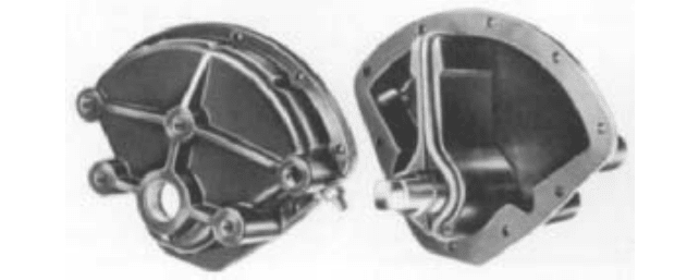
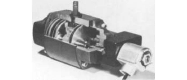
FIGURE 34 Rotary actuator with sealed blade (Vomox)
depends on valve type: ball and butterfly valves have higher recovery percentages than
do globe and angle valves. To avoid cavitation, which is the formation of vapor bubbles
near the vena contracta of the valve, followed by a sudden damaging collapse near the
metal, the static pressure at the vena contracta must be above the liquid vapor pressure.
This is easier to do with a low-recovery valve because the initial pressure drop need not
be as high for a given downstream pressure. Several factors have been devised to indicate
pressure recovery. One, C
f
, the critical flow factor, is the ratio of pressure recovery, vary-
ing for different valve openings. Another, K
m
, the valve recovery coefficient, is the ratio of
pressure drop across the valve to pressure drop between valve inlet and vena contracta
at that instant when flow begins to be choked by bubble formation. Both of these factors
will be higher for globe valves than for ball and butterfly valves, and the factors serve to
indicate valve suitability for marginal cavitation service.
ACTUATORS The motion needed to change the valve orifice area and to close the valve
tightly is produced by an actuator. The types of motion of the valve plug or disk are either
linear or rotary (Figure 34), the latter being usually 90° but occasionally as low as 70°.
These motions can be effected in several ways. The linear translating motion can result
from a cylinder or diaphragm actuator working directly or through linkage (Figure 35). A
screw thread at the stem top can convert a rotary motion to linear stem motion, or threads
at the stem bottom can engage threads in the valve disk so rotation of the stem moves
the disk. Geared electric motor drives (Figure 36), cylinders (Figure 37), and diaphragm-
and-spring actuators (Figure 38) are common with ball, plug, and butterfly valves. The
solenoid valve (Figure 39) relies on an electromagnetic force to move a disk directly or to
initiate the piloting action that allows line fluid to open the valve. The piloted solenoid
valve (Figure 40) relies on fluid pressures to open the main orifice.
The simplest actuator is the manually powered operator, which is a gear box. It pro-
vides enough mechanical advantage to overcome starting friction and to seal the valve
tightly. Provision for an impact blow to initiate opening is found in some operators.
The choice of actuator depends first on whether the service is on-off or modulating. For
on-off service, the actuator need have only enough force to overcome breakaway force or
torque and sufficient stroke to open the valve fully. Speed of operation is rarely critical,
and motion limits can be designed into valve or actuator. Pneumatically (Figure 41) and
hydraulically powered actuators usually stroke rapidly but can be slowed in either direc-
tion by auxiliary valving or controls. On some pneumatic actuators, times to five minutes
are possible. Electric-motor-driven actuators are slower than pneumatic or hydraulic types
and require limit switches to stop the motor at the end of travel.
In modulating service, where the actuator must hold a control valve setting,
demands are more severe.The speed of movement, expressed as stroking speed, is some-
times an important factor, especially in emergency shutdown or bypass. The stability of
an actuator is partly its ability to hold the valve setting under fluctuating or buffeting
7.24 CHAPTER SEVEN
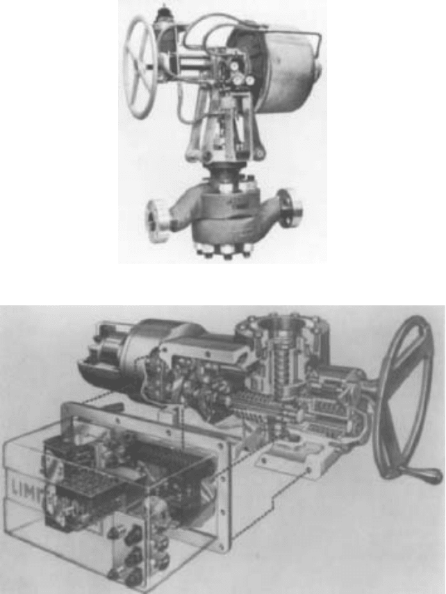
FIGURE 35 Linkage connects actuator and valve stem (Masoneilan International)
FIGURE 36 Electric-motor-driven actuator with mechanism for limiting torque (Philadelphia Gear)
loads from the fluid. Damping and high spring rate can help with this. The relation of
the natural frequency of the actuator and its adjacent elements to the frequencies
encountered in controlling the flow or those experienced from fluid buffeting can also be
important.
Stroke length is also a factor. Although the disk in a globe valve or similar type need
lift only one-quarter of the seat diameter to give adequate area for full flow, this distance
in large valves will exceed the 2-in (5-cm) stroke of most diaphragm actuators. If linkage
7 PUMP CONTROLS AND VALVES 7.25
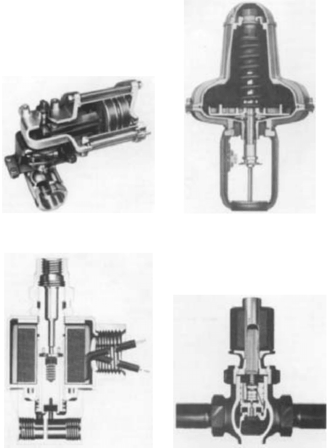
FIGURE 37 Cylinder actuator and linkage for ball
valve (Jamesbury)
FIGURE 38 Diaphragm-and-spring actuator,
reversible type (Foxboro)
FIGURE 40 Piloted solenoid valve relies on fluid
pressure to open main orifice (Magnetrol Valve).
FIGURE 39 Solenoid valve for three-way operation
is direct-acting (Skinner Precision Industries).
with its lever advantage is needed to increase thrust, the problem becomes more acute. A
cylinder or electric actuator is then necessary.
The source of power for the actuator influences choices too. One standard may be 3- to
25-lb/in
2
(0.2- to 1.7-bar) instrument air pressure, whereas in other cases much higher air
or oil pressure is available.
7.26 CHAPTER SEVEN
FIGURE 41 Opposed pistons drive rack-and-gear mechanism for 90° rotation in this pneumatic actuator
(Worcester Controls).
The diaphragm-and-spring actuator (Figure 38) is a very common type and has several
important advantages. The spring can be pre-loaded to cause the valve to either close or
open fully (be fail-safe) if control air fails. The spring also opposes the force generated by
the control signal, doing so in a manner giving proportional control. Of course, the spring’s
opposition negates much of the force available on the diaphragm, but the simplicity and
low friction of this actuator have made it very popular. Most modern types are reversing:
The fail-safe action can easily be changed from open to close by turning the diaphragm
enclosure upside down and reassembling.
POSITIONERS
With actuators that lack an internal spring, a positioner is needed to adjust
the valve position to the desired value. A positioner is a small feedback system that
receives an input signal (usually air pressure but sometimes an electric signal) from a con-
troller and adjusts a valve stem position to a prearranged corresponding value. The valve
stem position, which is the output, need not vary linearly with input pressure; cams in
the mechanism can give a wide range of stem position functions and thus apparently
change the characteristic of the valve.
The positioner is a necessity for actuators in which the valve stem position is not a
function of the actuator fluid pressure or electric current magnitude. Examples are pneu-
matic and hydraulic cylinders and electric motors. Even though positioners are not inher-
ently necessary on the diaphragm-and-spring actuator, they are sometimes applied. The
reasons for the application hold for other types of actuators, too.
Friction in the actuator diaphragm cylinder or valve stem packing is one reason. The
positioner can cut the dead-band from values such as 5 to 15% to less than 0.5% and can
give repeatability of 0.1% of full span.
Need for more force to close a single-seat valve tightly is another reason for using a
positioner. If loading pressure must be increased above a standard 15 lb/in
2
gage (1-bar)
value, the positioner can control air at a higher pressure and thus greatly increase the
stem force.
Split-range operation, in which different valves operate over different parts of the con-
troller output pressure range, calls for positioners. Reversal of valve action, too, is easily
achieved with positioners. A positioner can also speed up valve response because the low-
volume positioner will act faster than the high-volume valve actuator and can open a
larger air supply than that in the controller. A pneumatic amplifier or booster is an alter-
native way to do this. Finally, change in control valve characteristic, such as from linear to
equal-percentage, is also possible through a positioner cam.
Because a positioner is another control loop added to a system, its effect under dynamic
conditions may worsen overall performance. If changes or oscillations are slow, the posi-
tioner and actuator will follow them accurately and correct for them. For rapid changes,
however, the effect of the positioner can be harmful. Evidence shows that if the natural fre-
7 PUMP CONTROLS AND VALVES 7.27
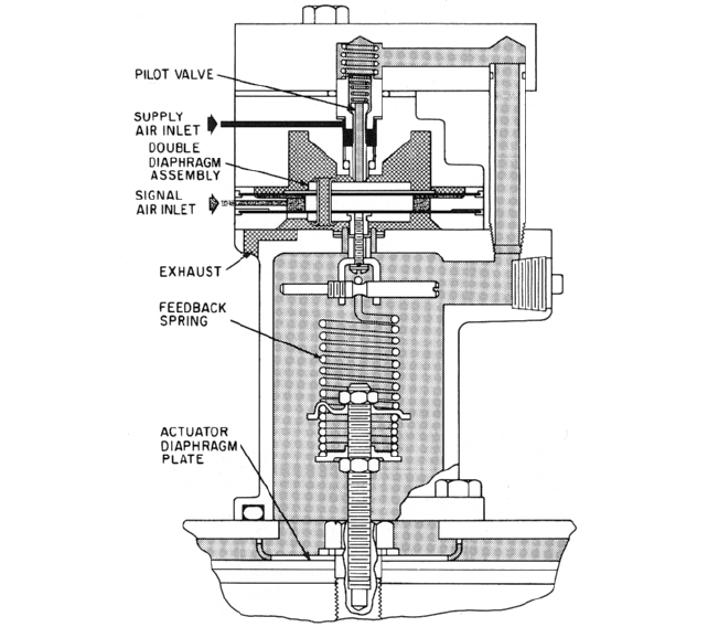
FIGURE 42 Force-balance positioner with spool and sleeve pilot valve (Masoneilan International)
quency of the complete process control loop is more than 20% of the frequency at which the
gain in the positioner-actuator system is attenuated 3 dB, the positioner will impair sys-
tem performance. Liquid level control systems are more likely to benefit from positioners
than are flow or pressure control systems.
Pneumatic positioners may be classified as force-balance or motion-balance types. In
the force-balance type, the force in the range spring inside the positioner is balanced
against control air pressure inside a bellows or double-diaphragm assembly. In the
force-balance positioner of Figure 42, the feedback spring, which can be adjusted for
range of pressure and initial actuation pressure, is attached to the actuator diaphragm
plate at the bottom and to a double-diaphragm assembly at the top. The upper
diaphragm has twice the area of the lower; introduction of signal air from the controller
into the space between the two diaphragms forces the assembly upward very slightly
but enough to lift a pilot valve at the positioner top and allow supply air pressure to
flow through and downward past the feedback spring to press the actuator diaphragm
down until forces balance. A reduction in signal pressure allows the double-diaphragm
assembly to move downward, first closing the pilot valve and then exposing a hole
through the pilot valve stem. Air then bleeds out from the actuator to atmosphere until
forces are again in balance.
In the force-balance positioner of Figure 43, flexure strips and a bell crank convert the
vertical actuator motion to a horizontal motion in the double-diaphragm assembly at the
top left and the supply valve at the right.
A motion-balance positioner showing the application of a cam to impart a characteris-
tic is shown in Figure 44.The cam at the lower right is pivoted and caused to rotate by the
7.28 CHAPTER SEVEN
FIGURE 43 Force-balance positioner with flexure linkage (ITT Hammel Dahl Conoflow)
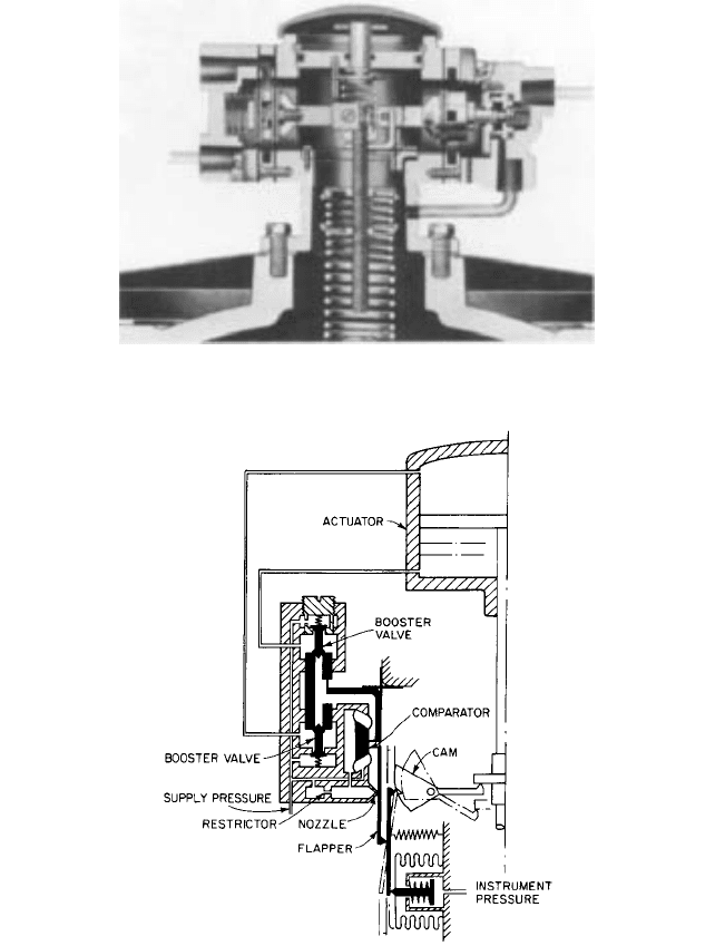
FIGURE 44 Motion-balance positioner with cam and diaphragm comparator (ITT Hammell Dahl Conoflow)
actuator stem motion. Supply pressure enters the valve assembly block at the left and goes
to both booster valves. It also bleeds through a restrictor and nozzle at the bottom of the
valve assembly block.The position of the flapper before the nozzle determines the pressure
in the diaphragm comparator at the right of the valve assembly block. An increase in sig-
nal air pressure to the bottom bellows moves one end of a balance beam and pushes the
flapper closer to the nozzle.This builds pressure in the diaphragm comparator and moves
it to the right. A linkage transforms this motion into a motion that opens the booster valve
7 PUMP CONTROLS AND VALVES 7.29
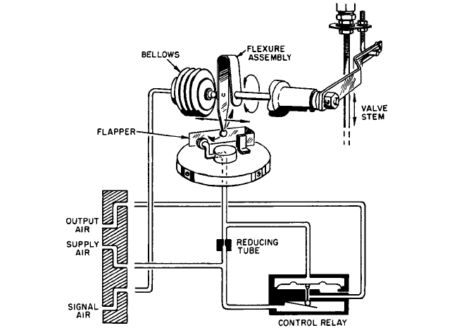
FIGURE 45 Motion-balance positioner with flexure assembly (Foxboro)
to supply air to the cylinder actuator top and permits air to exhaust from the cylinder bot-
tom. The actuator stem moves down until the feedback cam, aided by the comparator link-
age, has repositioned the flapper in front of the nozzle.
In another motion-balance positioner (Figure 45), signal air pressure from 3 to 15 lb/in
2
(0.2 to 1 bar) gage in a bellows opposes a flexure assembly on a shaft that is rotated by the
valve stem motion. An increase in signal air pressure to the bellows expands it and moves
the lower end of the flexure away from a flapper, permitting the flapper to move toward a
nozzle. The resultant buildup of air pressure on the diaphragm of the control relay at the
lower right closes the exhaust port and opens the supply port to allow air at fully supply
pressure to pass to the actuator. The valve stem motion rotates the flexure and thereby
shifts the tip touching the flapper. The flapper assumes an equilibrium position propor-
tional to the signal air pressure.
The pneumatic amplifier or booster is a special kind of regulator valve that develops an
output air pressure proportional to the input signal pressure. It can be used to boost pres-
sure on an actuator for faster action in cases where the instrument tubing is small-bore
and long and the actuator volume is large.
FURTHER READING __________________________________________________
ISA Handbook of Control Valves, Instrument Society of America, Pittsburgh, 1971.

Pump
Systems
C•H•A•P•T•E•R•8

SECTION 8.1
GENERAL
CHARACTERISTICS OF
PUMPING SYSTEMS AND
SYSTEM-HEAD CURVES
J. P. MESSINA
8.3
1
1 bar 1
5
Pa.
2
Work per unit weight mass, rather than weight force, is sometimes called specific delivery work; it has the units of
newton-meters per kilogram and is equal to total head multiplied by g, the gravitation constant.
SYSTEM CHARACTERISTICS AND PUMP HEAD___________________________
A pump is used to deliver a specified rate of flow through a particular system.When a pump
is to be purchased, this required capacity must be specified along with the total head neces-
sary to overcome resistance flow and to meet the pressure requirements of the system com-
ponents. The total head rating of a centrifugal pump is usually measured in feet (meters),
and the differential pressure rating of a positive displacement pump is usually measured in
pounds per square inch (kilopascals or bar
1
). Both express, in equivalent terms, the work in
foot-pounds (newton-meters) the pump is capable of doing on each unit weight (force) of liq-
uid pumped at the rated flow.
2
It is the responsibility of the purchaser to determine the
required pump total head so the supplier can make a proper pump selection. Underesti-
mating the total head required will result in a centrifugal pump’s delivering less than the
desired flow through the system.An underestimate of the differential pressure required will
result in a positive displacement pump’s using more power than estimated, and the design
pressure limit of the pump could be exceeded. Therefore, system pressure and resistance to
flow, which are dependent on system characteristics, dictate the required pump head rating.
THE PUMPING SYSTEM _______________________________________________
The piping and equipment through which the liquid flows to and from the pump constitute
the pumping system. Only the length of the piping containing liquid controlled by the