Рави Додданнавар, Андрис Барнард. Practical Hydraulic Systems
Подождите немного. Документ загружается.

88 Practical Hydraulic Systems
long wearing. Dual puipose *o'riitg
cartridge t^, v«th
b^kup
washar
bronze bu^ir^ Adequate porting
HI0) tensite steei,
stiper finished, hard
chrome ptated
piston rod
4 Wrench flats
Double acting
rod wiper
Assist or pry groove for
easy cartridge removal
Low friction, self«
adjusting, long
wearing,
muitl-Up
rod racking
Easily removed bronze
rod cartridge - held
in place by steel
retainer plate screwed
to the head
Steel tube
Tie rod constructksn for
maximum strength
SeH'iocking
tie rod nuts
All steel heads
and mountings
Tapered cushion
pistons for shock free
deceleration
Ductile Iron piston, threaded
and dowel screwed to rod
Ball check *o'
ring sealed
Extrusion proof
*o'
ring
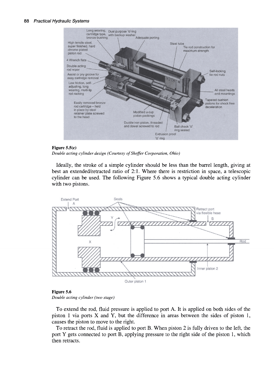
Figure 5.5(c)
Double acting cylinder design (Courtesy ofSheffer Corporation, Ohio)
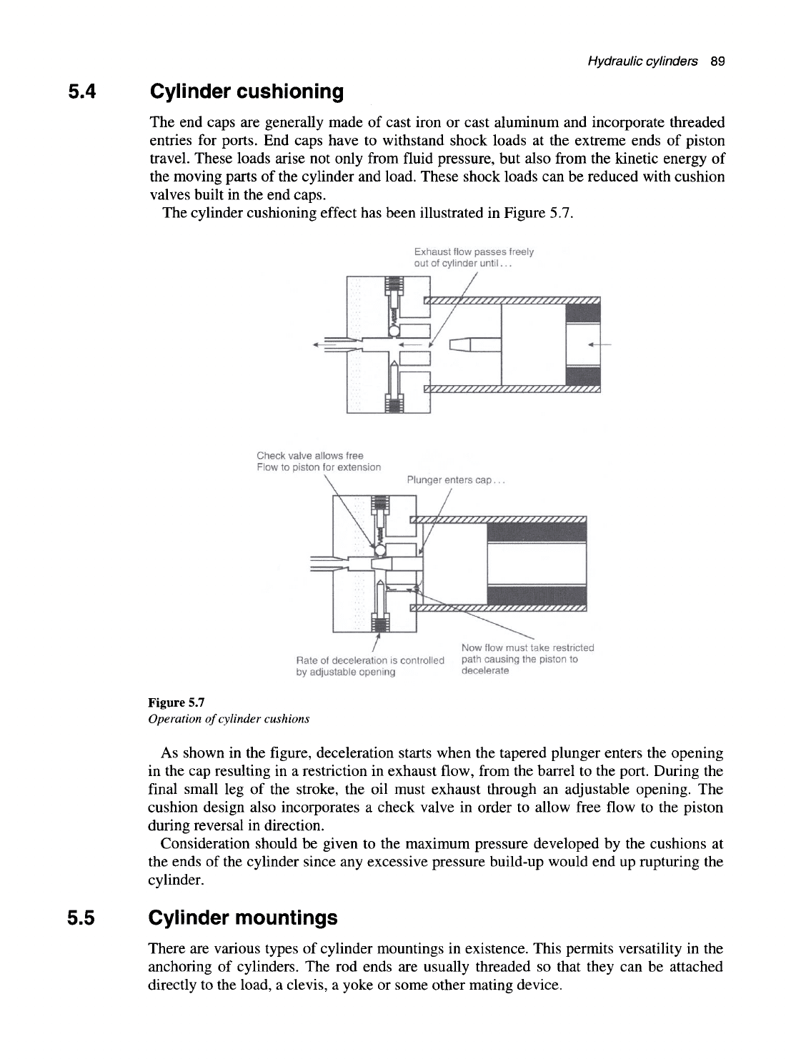
Ideally, the stroke of a simple cylinder should be less than the barrel length, giving at
best an extended/retracted ratio of 2:1. Where there is restriction in space, a telescopic
cylinder can be used. The following Figure 5.6 shows a typical double acting cylinder
with two pistons.
Extend Port
Seals
RXS3*[SSS
•.\\\\VV\V\\\\N Retract port
-^""•^—
KN
via flexible hose
] ^
#...1^
^X\\\X\\\X^
:\\\\\\\\\\\\\\\\\\\\\\\\\\\\\i
Outer piston 1
Inner piston 2
Figure 5.6
Double acting cylinder (two stage)
To extend the rod, fluid pressure is applied to port A. It is applied on both sides of the
piston 1 via ports X and Y, but the difference in areas between the sides of piston 1,
causes the piston to move to the right.
To retract the rod, fluid is applied to port B. When piston 2 is fully driven to the left, the
port Y gets connected to port B, applying pressure to the right side of the piston 1, which
then retracts.
Hydraulic cylinders 89
5.4 Cylinder cushioning
The end caps are generally made of cast iron or cast aluminum and incorporate threaded
entries for ports. End caps have to withstand shock loads at the extreme ends of piston
travel. These loads arise not only from fluid pressure, but also from the kinetic energy of
the moving parts of the cylinder and load. These shock loads can be reduced with cushion
valves built in the end caps.
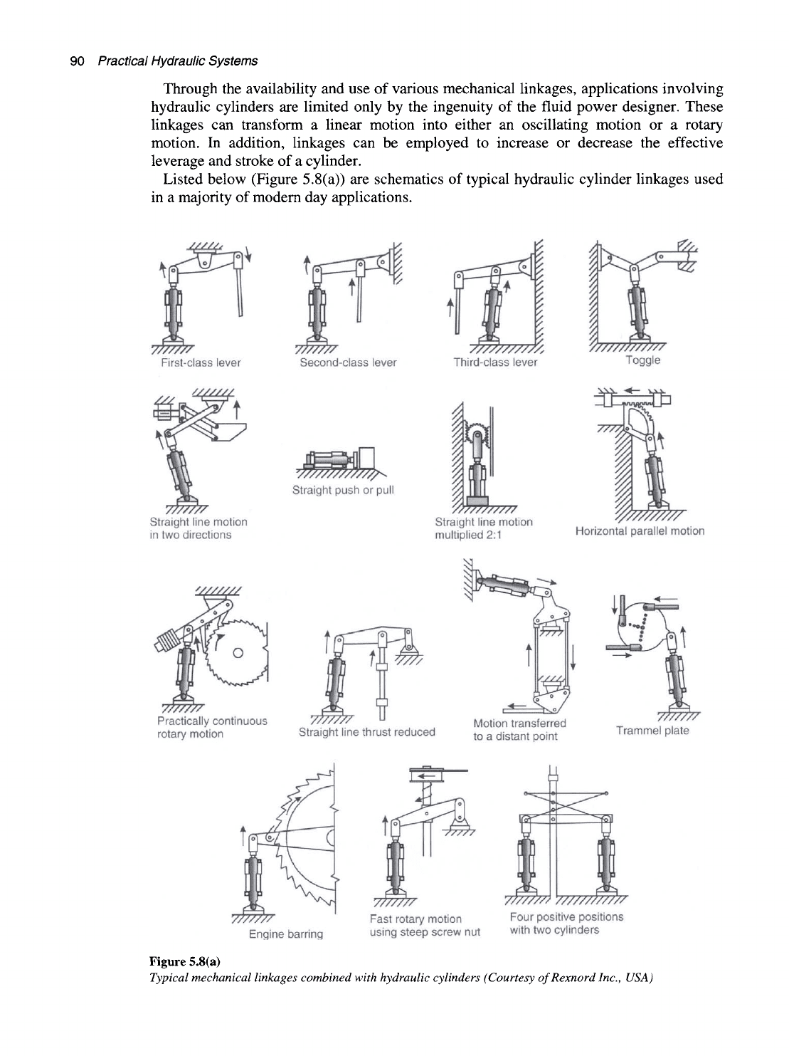
The cylinder cushioning effect has been illustrated in Figure 5.7.
Exhaust flow passes freely
out of cylinder
until...
Check valve allows free
Flow to piston for extension
Plunger enters cap.
Rate of deceleration is controlled
by adjustable opening
Now flow must take restricted
path causing the piston to
decelerate
Figure 5.7
Operation of cylinder cushions
As shown in the figure, deceleration starts when the tapered plunger enters the opening
in the cap resulting in a restriction in exhaust flow, from the barrel to the port. During the
final small leg of the stroke, the oil must exhaust through an adjustable opening. The
cushion design also incorporates a check valve in order to allow free flow to the piston
during reversal in direction.
Consideration should be given to the maximum pressure developed by the cushions at
the ends of the cylinder since any excessive pressure build-up would end up rupturing the
cylinder.
5.5 Cylinder mountings
There are various types of cylinder mountings in existence. This permits versatility in the
anchoring of cylinders. The rod ends are usually threaded so that they can be attached
directly to the load, a clevis, a yoke or some other mating device.
90 Practical Hydraulic Systems
Through
the
availabiUty and use
of
various mechanical Unkages, appUcations involving
hydraulic cylinders
are
limited only
by the
ingenuity
of
the fluid power designer. These
linkages
can
transform
a
linear motion into either
an
oscillating motion
or a
rotary
motion.
In
addition, linkages
can be
employed
to
increase
or
decrease
the
effective
leverage and stroke
of
a cylinder.
Listed below (Figure 5.8(a))
are
schematics
of
typical hydraulic cylinder linkages used
in
a
majority
of
modem day applications.
TTTTTTT
First-class lever
V//////
Second-class lever
V77777777A
Third-class lever
V7P7777777777
Toggle
7P7777
Straight line motion
in two directions
Straight push
or
pull
Straight line motion
multiplied
2:1
Horizontal parallel motion
V//////
7777777
Practically continuous
rotary motion
7777777
Straight line thrust reduced
Motion transferred
to
a
distant point
7777777
Trammel plate
7777777
Engine barring
7777777
Fast rotary motion
using steep screw
nut
7777777>
777777777777
Four positive positions
with two cylinders
Figure
5.8(a)
Typical mechanical linkages combined with hydraulic cylinders (Courtesy ofRexnordlnc, USA)
Hydraulic cylinders
91
In order to facilitate the smooth working of these mechanical linkages, various cylinder
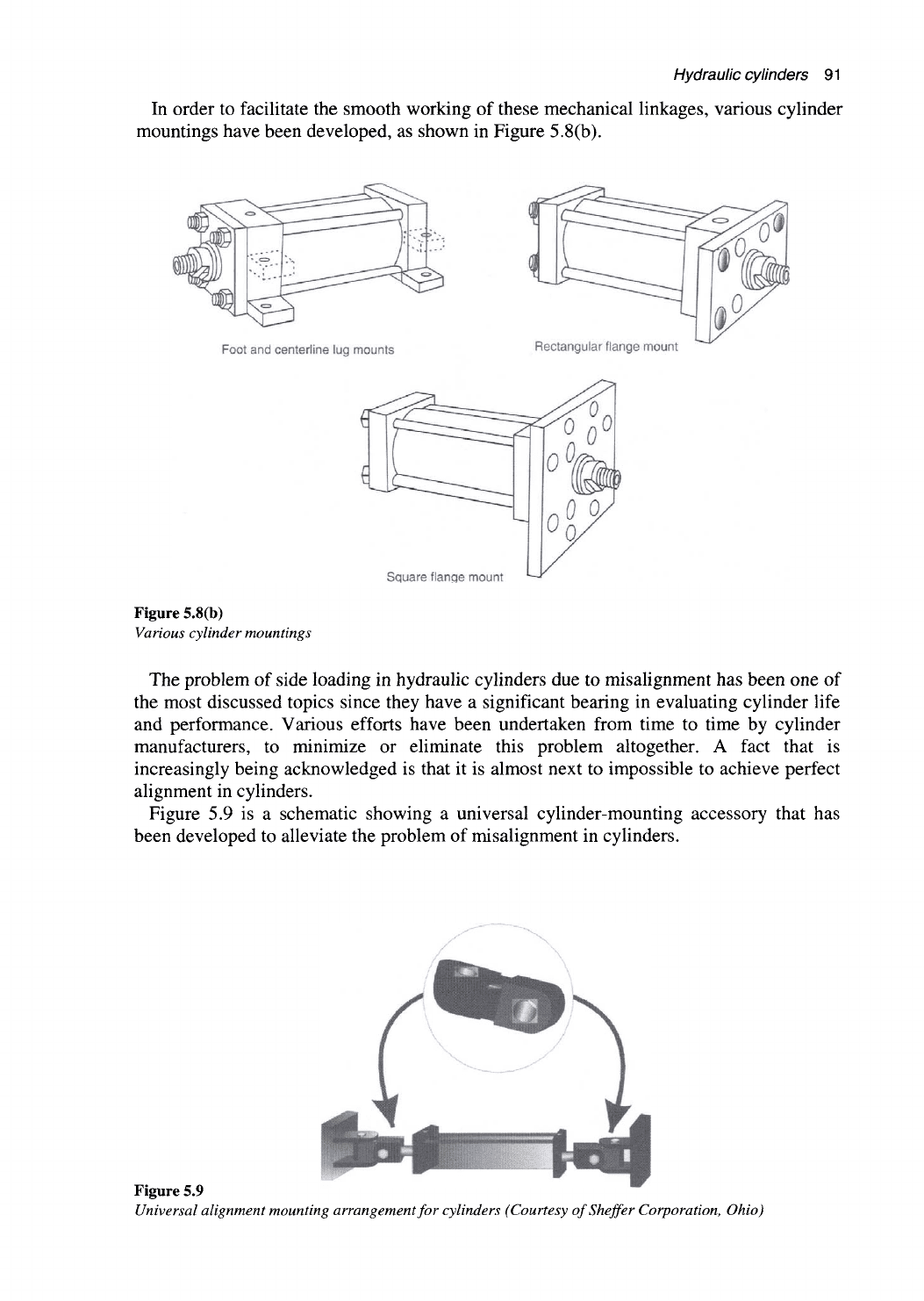
mountings have been developed, as shown in Figure 5.8(b).
Foot and centerline lug mounts
Rectangular flange mount
Square flange mount
Figure 5.8(b)
Various cylinder mountings
The problem of side loading in hydraulic cylinders due to misalignment has been one of
the most discussed topics since they have a significant bearing in evaluating cylinder life
and performance. Various efforts have been undertaken from time to time by cylinder
manufacturers, to minimize or eliminate this problem altogether. A fact that is
increasingly being acknowledged is that it is almost next to impossible to achieve perfect
alignment in cylinders.
Figure 5.9 is a schematic showing a universal cylinder-mounting accessory that has
been developed to alleviate the problem of misalignment in cylinders.
Figure 5.9
Universal alignment mounting arrangement for cylinders (Courtesy ofSheffer Corporation, Ohio)
92
Practical Hydraulic Systems
The advantages of these types of mounting accessories are:
• Ease of mounting
• Reduced cyUnder binding and side loading
• Allowance for universal swivel
• Reduced bearing and tube wear
• Elimination of piston blow-by, caused by misalignment.
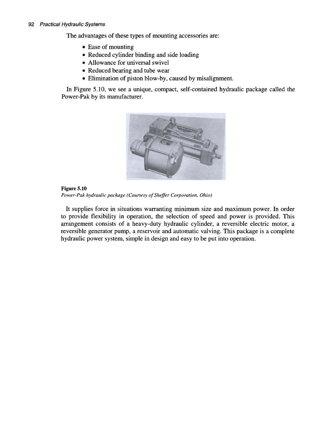
In Figure 5.10, we see a unique, compact, self-contained hydraulic package called the
Power-Pak by its manufacturer.
Figure 5.10
Power-Pak hydraulic package (Courtesy ofSheffer Corporation, Ohio)
It supplies force in situations warranting minimum size and maximum power. In order
to provide flexibility in operation, the selection of speed and power is provided. This
arrangement consists of a heavy-duty hydraulic cylinder, a reversible electric motor, a
reversible generator pump, a reservoir and automatic valving. This package is a complete
hydraulic power system, simple in design and easy to be put into operation.
Control components in a hydraulic
system
6.1 Objectives
After reading this chapter, the student will be able to:
Learn about the various control components used in hydraulics
Understand the purpose, construction and operation of different valves such as
pressure control valves, direction control valves and flow control valves and
also identify the related graphical symbols in a hydraulic circuit
Understand and explain the different methods of valve actuation
Differentiate between compensated and non-compensated flow control
Explain the purpose, design and operation of servo valves
Understand the concept of hydraulic fuses
Understand the function and purpose of shock absorbers in hydraulics
Learn about the operation of different types of temperature and pressure
switches.
6.2 Introduction
One of the most important considerations in a hydraulic system is 'control'. For any
hydraulic system to function as required, a proper selection of control components is
quite essential. Fluid power is primarily controlled with the help of control devices called
valves. The selection of these control devices involves not only choosing the right type
but also the size, actuating technique and its remote control capability.
In this chapter, we shall review in detail the working of various control devices in
hydraulic systems that are as listed below:
• Control valves
• Servo valves
• Hydraulic fuses
• Temperature and pressure switches
• Shock absorbers.
94
Practical Hydraulic Systems
6.3 Control valves
A valve is a control device used for adjusting or manipulating the flow rate of a liquid or
gas in a pipeline. The valve essentially consists of a flow passage whose flow area can be
varied. The external motion can originate either manually or from an actuator positioned
pneumatically, electrically or hydraulically, in response to some external positioning
signal. This combination of the valve and actuator is known as a control valve or an
automatic control valve.
Basically there are three types of control valves:
1.
Direction control valves: Direction control valves determine the path
through which a fluid traverses within a given circuit. In other words, these
valves are used to control the direction of flow in a hydraulic circuit. It is that
component of a hydraulic system that starts, stops and changes the direction of
the fluid flow. Additionally the direction control valve actually designates the
type of hydraulic system design, either open or closed. An example of their
application in a hydraulic system is the actuator circuit, where they establish
the direction of motion of a hydraulic cylinder or a motor.
2.
Pressure control valves: Pressure control valves protect the system against
overpressure conditions that may occur either on account of a gradual build up
due to decrease in fluid demand or a sudden surge due to opening or closing of
the valves. Pressure
reUef,
pressure reducing, sequencing, unloading, brake
and counterbalance valves control the gradual buildup of pressure in a
hydraulic system. Pressure surges can produce instantaneous increases in
pressure as much as four times the normal system pressure and that is the
reason why pressure control devices are a must in any hydraulic circuit.
Hydraulic devices such as shock absorbers are designed to smoothen out
pressure surges and also to dampen hydraulic shock.
3.
Flow control valves: The fluid flow rate in a hydraulic system is controlled
by flow control valves. Flow control valves regulate the volume of oil supplied
to different parts of a hydraulic system. Non-compensated flow control valves
are used where precise speed control is not required, since the flow rate varies
with the pressure drop across a flow control valve. Pressure-compensated flow
control valves are used in order to produce a constant flow rate. These valves
have the tendency to automatically adjust to changes in pressure.
Since it is important to know the primary function and operation of the various types of
control components, it is required to examine and study the functioning of each of these
valves in detail.
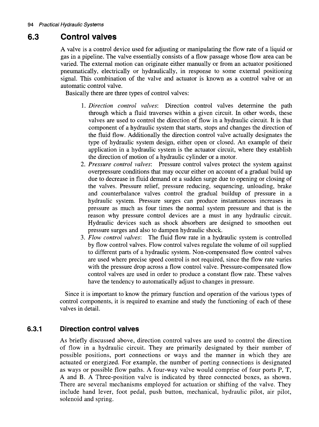
6.3.1 Direction control valves
As briefly discussed above, direction control valves are used to control the direction
of flow in a hydraulic circuit. They are primarily designated by their number of
possible positions, port connections or ways and the manner in which they are
actuated or energized. For example, the number of porting connections is designated
as ways or possible flow paths. A four-way valve would comprise of four ports P, T,
A and B. A Three-position valve is indicated by three connected boxes, as shown.
There are several mechanisms employed for actuation or shifting of the valve. They
include hand lever, foot pedal, push button, mechanical, hydraulic pilot, air pilot,
solenoid and spring.
Control components
in a
hydraulic system
95
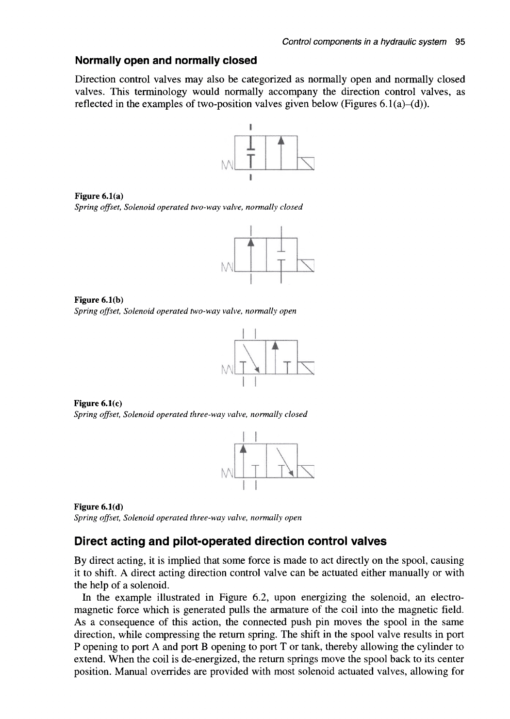
Normally open and normally closed
Direction control valves may also be categorized as normally open and normally closed
valves. This terminology would normally accompany the direction control valves, as
reflected in the examples of two-position valves given below (Figures 6.1(a)-(d)).
T
T
S
Figure 6.1(a)
Spring offset, Solenoid operated two-way valve, normally closed
i i
"^
m
Figure 6.1(b)
Spring offset, Solenoid operated two-way valve, normally open
I
I
m
i
I
I
Figure 6.1(c)
Spring offset, Solenoid operated three-way valve, normally closed
i
X
Figure 6.1(d)
Spring offset. Solenoid operated three-way valve, normally open
Direct acting and pilot-operated direction control valves
By direct acting, it is implied that some force is made to act directly on the spool, causing
it to shift. A direct acting direction control valve can be actuated either manually or with
the help of a solenoid.
In the example illustrated in Figure 6.2, upon energizing the solenoid, an electro-
magnetic force which is generated pulls the armature of the coil into the magnetic field.
As a consequence of this action, the connected push pin moves the spool in the same
direction, while compressing the return spring. The shift in the spool valve results in port
P opening to port A and port B opening to port T or tank, thereby allowing the cylinder to
extend. When the coil is de-energized, the return springs move the spool back to its center
position. Manual overrides are provided with most solenoid actuated valves, allowing for
96
Practical Hydraulic Systems
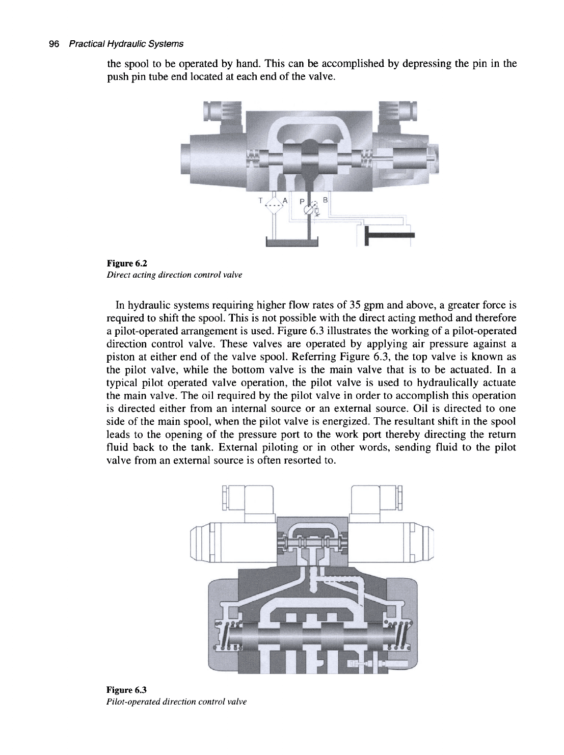
the spool to be operated by hand. This can be accomplished by depressing the pin in the
push pin tube end located at each end of the valve.
Figure 6.2
Direct acting direction control valve
In hydraulic systems requiring higher flow rates of 35 gpm and above, a greater force is
required to shift the spool. This is not possible with the direct acting method and therefore
a pilot-operated arrangement is used. Figure 6.3 illustrates the working of a pilot-operated
direction control valve. These valves are operated by applying air pressure against a
piston at either end of the valve spool. Referring Figure 6.3, the top valve is known as
the pilot valve, while the bottom valve is the main valve that is to be actuated. In a
typical pilot operated valve operation, the pilot valve is used to hydraulically actuate
the main valve. The oil required by the pilot valve in order to accomplish this operation
is directed either from an internal source or an external source. Oil is directed to one
side of the main spool, when the pilot valve is energized. The resultant shift in the spool
leads to the opening of the pressure port to the work port thereby directing the return
fluid back to the tank. External piloting or in other words, sending fluid to the pilot
valve from an external source is often resorted to.
Figure 6.3
Pilot-operated direction control valve
Control components
in a
hydraulic system
97
The advantages associated with external piloting are that the effect of any other
influence on the main system is not felt and the possibility of separate filtration ensures
silt-free operation of the pilot valve. Additionally, the valve may also be internally or
externally drained. In the case of internal draining of the pilot valve, the oil flows directly
into the tank chamber of the main valve. When operating the main control spool, pressure
or flow surges occurring in the tank port may affect the unloaded side of the main valve
as well as the pilot valve. This may be avoided by externally draining the pilot valve or in
other words, feeding the pilot oil flow back to the tank.
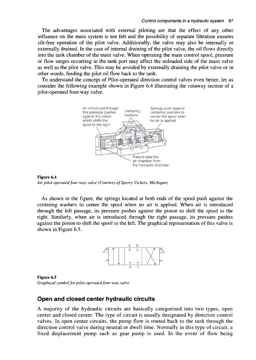
To understand the concept of Pilot-operated direction control valves even better, let us
consider the following example shown in Figure 6.4 illustrating the cutaway section of a
pilot-operated four-way valve.
Air introduced through
this passage pushes
against the piston
which shifts the
spool to the right
Centering
washers
Springs push against
centering washers to
center the spool when
no air is applied
Pistons seal the
air chamber from
the hydraulic chamber
Figure 6.4
Air pilot-operated four-way valve (Courtesy ofSperry Vickers, Michigan)
As shown in the figure, the springs located at both ends of the spool push against the
centering washers to center the spool when no air is applied. When air is introduced
through the left passage, its pressure pushes against the piston to shift the spool to the
right. Similarly, when air is introduced through the right passage, its pressure pushes
against the piston to shift the spool to the left. The graphical representation of this valve is
shown in Figure 6.5.
^
/^/>
i V
^
r
A B
X ±
T T
Y
A
b.
Figure 6.5
Graphical symbol for pilot-operated four-way valve
Open and closed center hydraulic circuits
A majority of the hydraulic circuits are basically categorized into two types, open
center and closed center. The type of circuit is usually designated by direction control
valves. In open center circuits, the pump flow is routed back to the tank through the
direction control valve during neutral or dwell time. Normally in this type of circuit, a
fixed displacement pump such as gear pump is used. In the event of flow being