Roll Forming Handbook / Edited by George T. Halmos
Подождите немного. Документ загружается.

4.2.6 Straightening Units
Straighteningunits support thestraightening
tools (rolls and blocks) and provide the tools’
movement in the horizontal and vertical direc-
tions as well as their rotation. The straightening
unit and the tools (usually called the “straigh-
tener”) are almost exclusively located after and
close to the last roll forming pass. The position of
the straightener is critical. Installation can be
made easier if the base of the straightener is keyed
to the base of the mill or other subbase. The key,
fastened to the mill bed, will locate the straigh-
tener always in the same position.
The position of the center of location of the
straightener die is critical. The center of rotation
should be about at the center of gravity of the
product (Figure4.9).
The straightening unit must be sturdy.The
strength is required to bend and twist the product
beyond its yield strength. It must also withstand
the full longitudinal pushing forcecreated by the
mill without being damaged when the product
hits it during the feed-in operation or when the
product got stuck in the straightener.Inthese
cases, the product should buckle in the short
distancebetween the last pass and the straightener
without causing damage to the straightener.
The straightener has to be easily,quickly,and
precisely adjustable. Asingle push–pull screw
can movethe straightener horizontally.Another
single push–pull screwcan movethe tool holder
up and down.The die holder can be rotated by
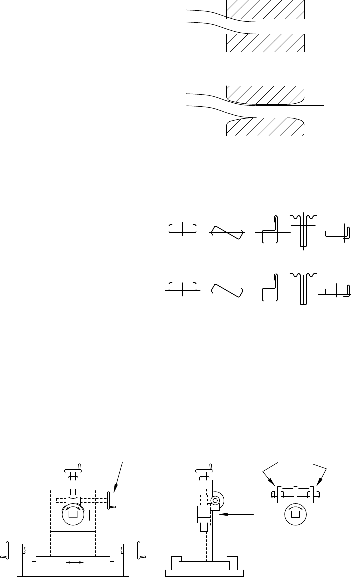
ahelical gear type of arrangement (Figure 4.10 Alternative1)orbyanother push–pull screw.However,
the operator usually can adjust the straightener with better accuracy in either direction when pushing it
with one screwagainst another stop screw(Figure4.10 Alternative2).
(b) correct straightener block
(a) incorrect straightener block
FIGURE 4.8 Advantage of the “fish-mouth”straightener
entry.
BAD
GOOD
FIGURE 4.9 Thelocationofthe centerlineofthe
rotating straightener is critical.
product
ALTERNATIVE 2
ALTERNATIVE 1
FIGURE 4.10 Different ways to rotate the straightener unit.
Roll Forming Handbook4 -6
When the straightener tools are rolls, then the
contacts between the rollsand products are lines.
This allows the horizontal or vertical movements
in straight lines. However,ifthe straightener
blocks are long blocks, then the straight-line
movement will in duce addi tionalstresses.
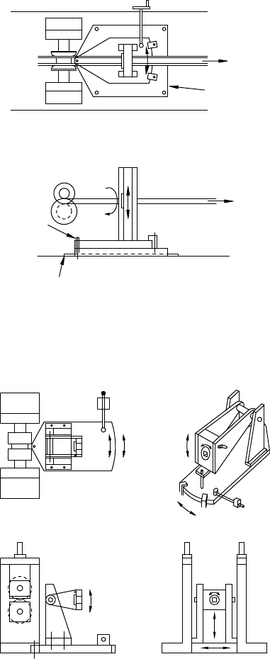
Therefore, it is better to movelong straightener
blocks in acircular motion rotated around apin
or shaft. This orientation will yield less internal
stresses and better results (Figure4.11). Unfor-
tunately,the best straightener arrangement of
moving thestraightener blockincircular
motionsorinbothhorizontal andvertical
directions is moreexpensive(Figure4.12), and
therefore it is seldom used.
4.2.7 Special Straighteners
The industrydoes not havea“standardstraight-
ener.” Individual companies mayhavetheir own,
repeatedly used design for straighteners to suit
their requirements.
Afew unusual, special, straightening units are
listed below.
4.2.7.1 Straightener with Their Own
Product Holding Tools
The product is usually straightened between the
last pass and the straightener.Therefore, the last
pass in the roll forming mill is exposed to similar
forces as the straightener.Ifthe last pass rolls are
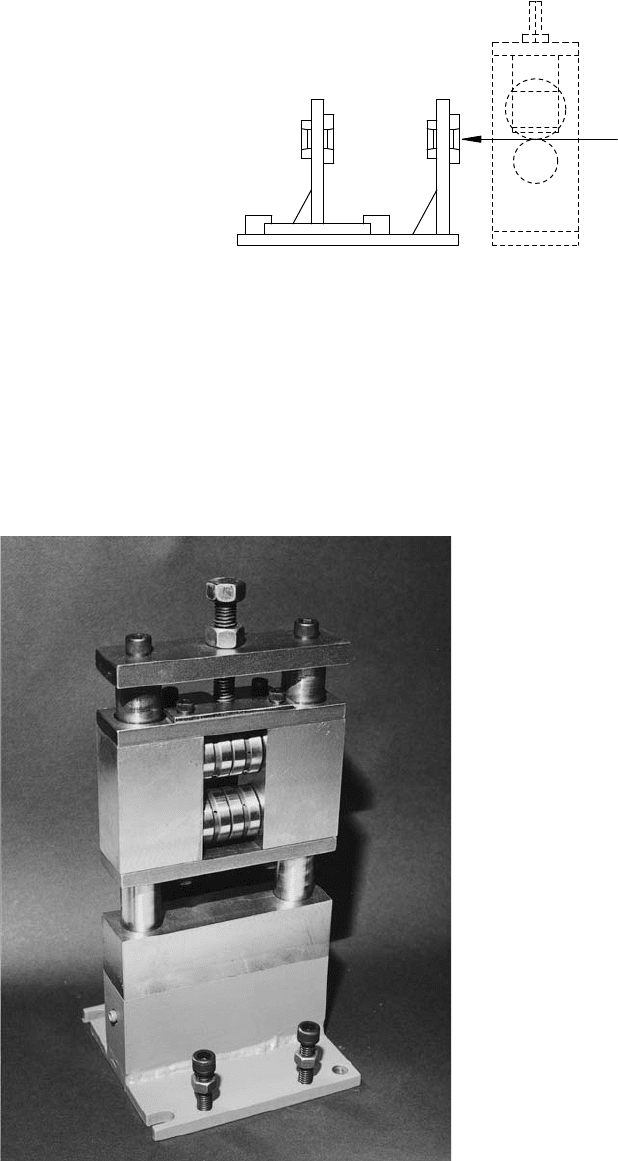
not designed to hold the section rigidly,donot
envelop it or if the rolls are thin, then the
straightener must have aproduct holding tool
aheadofthe straig htener (Figure4.13).A
reasonable distance between thestraightener
and the product-holding tool must be kept
because too shortofadistancewillincrease
the forces required for straightening.
4.2.7.2 Straightener with Vertical
Movement Only
In some instances, the designer can foresee bow
in the vertical direction only,without acamber
or twist. In this case, asimple straightener with vertical movement only is sufficient (Figure4.14).
Similarly,ifthe designer foresees acamber only,then amovement in the horizontal direction will suffice.
When wide, flat panels with relatively small edge bends are formed, the panel can easily haveabowor
twist. Occasionally,itcan happen that one edge is moving up and the other one is moving down. Simple
straighteners, moving only up or down at both edges independently,can be used for this type of products
(Figure4.15).
last pass
base plate
edge of
mill bed
base plate
pin
key
FIGURE 4.11 Adjusting the straightener block in a
circular motion is preferred.
FIGURE 4.12 To provide circular motion in all directions
is morecomplicated.
Secondary Operations in the Roll Forming Line 4 -7
4.2.7.3 Motorized Straightener
The threestraightener movements (vertical, hori-
zontal, and rotational) can be motorized. Motor-
ized straightener can be accurately adjusted during
operation. They are operator friendly,especially
in the case of strong sections. If required, the
straightener can be remotely adjustedfrom a
product checking location, positioned after the
cutoffdie.
4.2.7.4 Automated Straightener
If the bow, camber,and twist are checked with
appropriate sensors, the results can be fed back
throughaPLCorcomputertoadjust the
straightener (Figure4.16). This automated
straightener will yield products with averynarrow
tolerancerange.
4.2.7.5 Straightener with the Driven Rolls or Belts
During the straightening process, the product is pushed through the straightening tools by the roll
former.The mill operators frequently haveproblems to pull out the last pieceofthe coil from the
FixedAdjustable Last pass
FIGURE 4.13 Afixedunit enveloping the productis
positioned ahead of the adjustable straightener.
FIGURE 4.14 Roller straightener to correct bow. (Courtesy of Delta Engineering Inc.)
Roll Forming Handbook4 -8
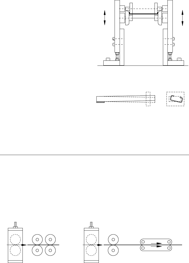
straightener once the product exited from the last
pass. Forthis reason, reprecut pieces cannot be
straightened with the usual straightener.
However,there is no reason whythe finished
product cannot be pulled out from the straightener
with driven rolls or belts (Figure4.17). The surface
speed of the rollsorbelts can be synchronized with
the speed of the product, or other arrangements
can be made such as permitting some slippage
between the pullout device and the product, or
using aslip clutch or utilizing the sensors.
Driven-roll straighteners, especially combined
with the previously mentioned holding tools can
also be used for manyprecut products.
4.2.7.6 Flare Straightener
To remove/reduce flareatthe end of the products,
special straighteners are used, as described in
Section 5.4.4. However,these units are only flare
remover/reducersand notthrough-product
straighteners.
4.3 Tight or Loose Line: Cutting Before, In-Between,
or After Roll Forming
4.3.1 General
Althoughthe strip moves continuously during roll forming, some operations in the line can be
completed by the stationarystrip (section) method. The location, technology, equipment, and tooling of
the secondaryoperations as well as the resulting qualitywill be influenced by whether the partismoving
or is stationary.
4.3.2 Precutting before Forming
Pieces cut to length before rollforming can run throughthe mill without stopping.However,some
products are stopped for other operations before rollforming,between two roll forming mills, or after
FIGURE 4.15 Straightening the bend-lines at the edges
is sufficient in flat panels.
Last pass
Fixed
driven
straightener
Adjustable
straightener
Last pass Driven"PULL-OUT" beltAdjustable
straightener
FIGURE 4.17 Driven straightener.
fixed end
measuring unit
FIGURE 4.16 Deviationfromstraightness canbe
measured with sensors.
Secondary Operations in the Roll Forming Line 4 -9
roll forming.Punching,notching,bending,resistancewelding,and manyother traditional operations
can be executed with stationarydies on the stationarystrips or products.
4.3.3 Cutting to Length between Roll Forming
Passes (or between TwoLines)
Occasionally,the product is partially formed, then cut to length beforefinal forming is accomplished.
This technologymay be applicable to complex shapes which would either make postcutting difficult,
if not impossible, or for other considerations. The cut partcan then continuously processed throughthe
remaining partofthe roll former at somewhat higher speed.
4.3.4 Secondary Operation in the Line after Postcutting
This is acommonapproach. After cutting to length, the formed product is either accelerated forward or
dropped to alower level, or moved sidewaysfor the next operation. Atypical example is the ceiling tile
support“T” rails. They are often roll formed at highspeed, cut to length witharelatively loose tolerance,
and then movedsideways for progressivetrimming to accurate length, punching,notching,and other
operations.
4.3.5 Tight Lines
In atight line (Figure 4.18), everypartofthe strip is moving until it is cut to length. Therefore, in
processes wherethe tool is engaged in the moving material such as punching,embossing,louvering,and
manyothers, the die must travel (fly) with the material. During this process, the flying die is accelerated
from its standing (home) position to match the speed of the material, the operation completed
(press down and up), while the die moves at the same speed as the material, then the die is decelerated,
stopped, and returned to its home position.
The length sensing system, the die accelerator,the press type, and the speed fluctuation of the strip has
the greatest influenceonthe length tolerances (see Chapter 3and Table 10.5).
4.3.6 Loose Line (“Free Loop” in and “Free Loop” out)
In aloose line (Figure4.19), the strip is firstly fed into the press considerably faster than the forming
speed of the mill. Then, the strip is stopped, operations are performed, and then the strip is quickly
pushed through (or pulled out from) the press. The loop ahead and beyond the press permits quick strip
acceleration and highspeed. Often, it is easier to accelerate and stop the lightweight strip in one direction
than to accelerate and decelerate the hundreds or thousands pounds (kg) flying die in twodirections.
In loose lines, the accuracy of the feeder is the most critical factor in length tolerance.
4.3.7 Punching in Loose Line
In the case of loose lines, the complete process (press, tools, feeder,etc.) can be similar to the one used in
the press shops. However,the continuous strip is pulled by the roll forming mill with asteady speed.
Therefore, in addition to the customaryloop ahead of the press, another loop is required after the press,
as shown in Figure4.19.
The loop ahead of the press controls the speed of the device feeding the material into the loop.Usually,
this feeding device is adriven uncoiler or aflattener with pinch rolls. To avoid sudden jerky starts and
stops, it is advisable to use variable speed drives which only decelerate and accelerate the loop feeding
device.
The loop after the press station sometimes governs the press, especially if the mill is slow.Atfaster
speeds, the loop may control the acceleration or deceleration of the rollforming mill.
Roll Forming Handbook4 -10

ROLL FORMING MILL
FLATTENER
UNCOILER
DOUBLE
PRE-PUNCH
PRESS DIE
ACCELERA
TOR
ENTR
YGUIDE
CUT OFF
PRESS
STRAIGHTENER
RUNO
UT TABLE
DIE
ACCELERA
TOR
FIGURE 4.18
Tigh
tline with flying prepunching operation.
Secondary Operations in the Roll Forming Line 4 -11
4.3.8 Loop before and after the Press
Different types of loops are applied in the roll forming lines.
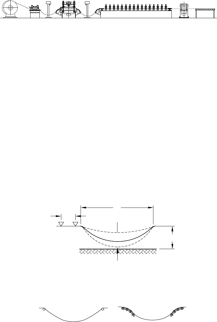
4.3.8.1 Free Hanging Loop
In manycases, the difference between the length of the loose loop and the tight loop (almost straight line
as shown in Figure4.20)issufficient to feed the press. Usually,reference literatureand suppliers provide
equations to calculate the space (length) required for adequate loop (markedas“L” in Figure4.20).
It is prudent to apply fixed or adjustable “basket rolls” (Figure 4.21)atboth ends of the loop to avoid
coil breaks.
Althoughafree hanging chain or rope follows apredictable geometric shape, the stiffness of the
strip will change that shape. If punching or notching significantly reduces the strip’s cross-section,
then the strip’s resistance to bending under its own weight can drastically change at that point.
These changes should be takeninto consideration when the distance between the supports (L) is
calculated.
ENTRY GUIDE
DOUBLE
UNCOILER
FLATTENER PRE-PUNCH
FEEDER
LOOP
LOOP
CUT OFF
DIE
ROLL FORMING MILL
STRAIGHTENER
RUN OUT TABLE
PRESS
PRESS
ACCELERATOR
FIGURE 4.19 Loose line with stationaryprepunching operation.
Tight
limit
Loose
limit
L
l
L
t
L
H
F=feed
length
FIGURE 4.20 Loop lengths determine the maximum feed length.
Not recommended Recommended
FIGURE 4.21 Basket rolls minimize damage to the coil.
Roll Forming Handbook4 -12
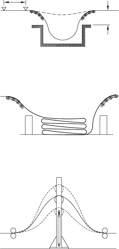
4.3.8.2 Free Hanging Loop with Pit
Forlong punching patterns (e.g., 3to10ftor1
to 3m), frequently thereisnot enoughdepth
between the supports and the floor to provide
sufficient length for the fast feeding.Inthis
case, the designer may recommend using pits
(Figure4.22). Pits can be useful but they are
expensive, not safe, and will create additional
expenses when the lines are moved.
4.3.8.3 Folded Free Loop
To avoid making pits in the plant floor,very
seldom the excess loop length is allowed to
create afreefolding loop (Figure4.23). The
loops, in abox-typestructure,are supported at
thestrip edges. Theequipment supplier
occasionally uses folded freeloop during setup
tests wherethe floor does not haveapit. This
system is not recommended in production lines,
because the strip surface can be damaged and it
is difficult to control the loop and the speed of
the operation.
4.3.8.4 Forced Loop
To reduce the space requirement and to avoid
the use of pits, the loop can be forced upwards
(Figure4.24). The weight of the strip and the
top roll is balanced by counterweights or by
cylinders. It can be economically used in front
of roll formers but the speed of the ascending
anddesce ndingtop roll canrestrictits
application in lines with fast accelerating press
feeders.
It is thetooland equipmentdesigner’s
function to evaluate all factors, to consider
the advantages and disadvantages, and to select
the best process. Usually,the production speed,
length, and variations of the pattern (e.g., hole
pattern created by each stroke), tolerancerequirements, method of synchronizing the cutoff, or other
operations with the previous operation, the type and thickness of material, the shape of notching or
punching,and the price will determine the technology. It is feasible to process one product in tight line
and another one in loose line in the same rollforming line.
4.3.9 Stop-and-Go Line
It is extremelyrare to stop the line for cutting to length or for other operations. Atypical application of this
stop-and-go operation is the low speed truck-mounted eaves troughforming.The truck-mounted mill
is stopped at the desired product length and the stationarytroughiscut with ahand shear.
F=feed
H
length
FIGURE 4.22 Loop length increased by using apit.
FIGURE 4.23 Folded free loop.
FIGURE 4.24 Forced loop.
Secondary Operations in the Roll Forming Line 4 -13

4.4 Location of the SecondaryOperations
The secondaryoperations can be performed
before, in-between, or after the roll forming
operation. For asingle purpose line or for large
production run quantities, it is feasible to choose
the most effective sequenceofoperations. As a
result, asingle line may consist of one, two, or
three uncoilers, one, two, three, or four roll
forming mills, several presses or other equipment. The possible combinations are almost limitless.
Choosing the right sequence of operations is very important because it will influencethe productivity,
quality, and manufacturing costs for manyyearstocome.
Even averysimple product such as a“U” channel with six holes (Figure 4.25)can be made in at least
20 different ways as shown in Table 4.1; Some of them are illustrated in Table 9.2 to Table 9.6.
Each method will yield similar looking Uchannels with six holes, but each one will havedifferent
tolerances, productivity, product cost, and equipment/tooling investment.
The selection of the sequence of operations is influencedbythe quantitytobeproduced, frequency
of changes, the product cross-section, location of notches, cutouts, their distancefrom the bend lines and
strip edges, dimension and tolerance requirements, as well as the available equipment and funds.
Some operations naturally fit into one placeonly.The moreoperations are incorporated in the line, the
morecombinations (permutations) are possible, and thereforethe sequence of operation will become
morecritical.
4.5 Stationaryand Flying Dies
4.5.1 Stationary Dies
The punching,notching,mitering,and other operations can be similar to the ones used in the press
shops. However,the subsequent rollforming and other processes must be considered at the die design
stage. Some of the added factors can be the direction of burr,distanceofcutouts from bend lines, how
FIGURE 4.25 Uchannelwith six holes.
TABLE 4.1 Different Ways to MakeUChannels with Six Holes
First Operation Second Operation Third Operation Variations
Precut strip Punch one, two, three, or six
holes at atime
Roll form 4
Precut strip Roll form Punch one, two, three, or six
holes at atime
4
Punch strip —punch two or
six holes at atime
Roll form afterwardsCut to length 2
Roll form Punch twoorsix holes at
atime
Cuttolength 2
Roll form Punch four holes Cuttolength and punch two
holes
1
Roll form Punch twocenter holes Cuttolength and punch six
holes (two at each end)
1
Roll form Punch six holes and cut to
length in the same die one
operation
1
Roll form Cuttolength Punch one, two, threeorsix
holes at atime
4
Rotarypunch holes Roll form Cuttolength 1
Total: 20
Roll Forming Handbook4 -14
and in what position will the partbecut off, strip continuity(at end mitering), effect of strip camber on
hole and notch locations, possible addition of ahole for the cutoffdie pick-up pin, and others.
Forvariable hole, notch, and embossment patterns, gags can control the punches and other tooling.
Moving the gags in and out by air cylinder or by other devices, controlled by PLCs or computers,
can makechanges from hit to hit to create the specified patterns.
In the quick-change lines, wherewidths or shapes of roll formed profiles are modified in ashorttime,
quick-change tooling should be used. Frequently,only the location of the subdies in apress or the
locations of small hydraulic presses are changed. Die or press location changes can be made with servo
motors or cylinders, which are often controlled by computers or PLCs.
Dies used in the stationaryoperations in most cases are similar to the ones used in the press shops. The
loops in the loose lines provide similar feed–stop–perform operation cycles. To ols, dies, and feeders are
conventional ones, but some additional factors should be considered:
*
Orientation of the product (e.g., direction of burr,left-right, etc.). Fordetails, see Chapter 5
(RollDesign).
*
Requirementofinthe subsequent operations (e.g., added hole for cutoffdie pick-up pin).
*
Finished products can be very long (e.g., for prepunching, special long presses, or press brakes
maybeused, but camber in long strip or sheets must be considered).
*
Variable length pattern (e.g., variable hole pattern requires programmable rotaryfeeder
or application of several smaller presses withadjustable positions).
*
Variable pattern (e.g., combination of gagged punches and programmable rotaryfeeder
or application of several smaller presses with adjustable positions).
*
Combination of stationaryprepunching and flying postpunching.
4.5.2 Flying Dies
Althoughthe function of aflying die can be identical to astationarydie, its construction is different.
Stationarydies are solidly attached to and well supported by both the bottom and top press surfaces
(bed and slides). The deflection of these conventional press bed surfacesislimited to about 0.0005
to 0.0010 in./ft (0.042 to 0.083 mm/m).
Flying dies slide on narrow rails. The upper die set is either attached to the press head (ram) rail or only
to the bottom die. The die shoe has to be strong enoug htobridge over the rails. However,excessive die
weight increases the forces required to accelerate and decelerate them.
Therefore, relying on the strength of the die/die shoe combination, the roll forming press designers
usually do not adhere to the previously mentioned press bed deflection restrictions.
The flying die set has to be accelerated from the standing position to maximum speed (sometimes up to
400 to 600 ft (120 to 180 m) per minute in afraction of asecond), then decelerated, stopped, acceleratedin
the opposite direction, decelerated, and stopped at the home position within atotal of 1.5 to 0.15 sec.
The die accelerator is usually attached to the bottom die shoe. The inertiacreated by the weight
of the top tool and die plate during acceleration and deceleration generates a“whipping” effect.
Therefore, the fly ing die must havelarger,sturdierposts, and guides than the stationarydies.
Brass plates are fastened to the die rails to reduce friction during the die travel. To improveaccuracy
and to further reduce friction, better dies havespring-loaded rollers running on the hardened steel
rails. The springs are lifting the die up 0.010 to 0.020 in. (0.25 to 0.50 mm) above the bottom press
rails. When the press head moves down and the punches engage the strip,the pressure suddenly
increases. Under the increased pressure,the springs collapse and the brass plates will supportthe full
load. When the head (ram) starts to moveup, the springs lift the die, which then moves on rollers
again.
In most cases, the top die plate rails are hooked to the press head rails (Figure4.26).
If an angular or rotary tool movement is required and if the die is small, then the die is attached only to
the bottom rails. The press head hits the brass plate fastened to the top of upper die plate, hence the dies
Secondary Operations in the Roll Forming Line 4 -15