Sarkar N. (ed.) Human-Robot Interaction
Подождите немного. Документ загружается.


Possibilities of force based interaction with robot manipulators
451
3. Dynamics in force based human robot interaction
3.1 Desired impedance behaviour
In the previous section the kinematics of the robot motion during force based human robot
interaction was detailed discussed. For comparison of the task space with the joint space
approach the desired impedance behaviour, introduced as the relationship between
interaction forces/torques and desired velocities, was simplified to direct proportional
dependency, see (11) or (12). In this case all acceleration and deceleration processes have to
be performed infinitely fast which is not feasible for the real robot manipulator. Applied to a
mechanical system it would mean that the mass of the system is zero. Hence, the desired
impedance behaviour has to be extended. One suitable choice is the behaviour of a simple
mass damper system. It is described by two parameters mass m and damping d. Applied to
joint space the particular desired joint velocity can be calculated from the interaction joint
torque or force τ by:
DD
qdqm
⋅+⋅=τ
(13)
The desired joint velocity can be integrated to get the desired joint position q
d
which may be
connected to the joint position control loop.
It is possible to extend the desired impedance behaviour with some additional features. One
very important feature is the dead zone nonlinearity within the interaction force branch to
prevent unintentional drifts of the manipulator arm. The undesirable robot motions during
force guidance, e.g., are the result of force/torque measurement inaccuracies or imprecise
gravity compensation of the tool. For several applications, except the force based teach-in
process, it may be convenient to insert the spring into the desired impedance behaviour.
This will result in spring mass damper behaviour which will bring the robot end-effector
back to starting position. It is described by Eq. (14) where k represents the spring constant:
DDD
qkqdqm ⋅+⋅+⋅=τ
(14)
Very important for the operator security is to bound the desired joint velocity of the desired
impedance behaviour. However, in the robot controller also the current joint velocities and
the current Cartesian end-effector velocities have to be supervised and limited according to
valid standards (Deutsches Institut für Normung, 1993). For the direct human robot
interaction in the automatic mode without deadman button it may be necessary to use a
two-channel safety controller to supervise the robot controller (Som, 2004). Besides velocity
limitation of the joint its position should also be bounded. This can be realized by a limiting
nonlinearity in the desired velocity branch together with an anti-wind-up feature. Apart
from this hard limit stop a comfortable alternative is the soft position limit stop. For this
purpose the damping d of the desired impedance behaviour may be increased in the
neighbourhood of the joint position boundary or an additionally spring behaviour can be
activated. The just introduced feature allows the operator to feel the joint boundaries
intuitive during force based human robot interaction.
3.2 Intuitive collision avoidance
Besides the implementation of the virtual joint boundaries already mentioned while
thinking of the desired impedance behaviour, a lot of features are imaginable to make the
force based human robot interaction more comfortable. One of these features is the intuitive
collision avoidance. In contrast to the joint boundaries it is realized in task space. The aim
Human-Robot Interaction
452
which should be achieved is that the operator guiding the robot will be detained to bring the
end-effector in contact with an obstacle located within the robot workspace. Such
functionality may be important in particular when obstacles are present after the teach-in
process is finished. It is possible to use, e.g., the CAD data of the robot work cell to generate
the intuitive collision avoidance.
There are a lot of possibilities to implement virtual restrictions of the robot workspace
during force guidance. One very interesting approach are force potential fields, (Choset et
al., 2005). Virtual forces act on the robot end-effector against the operator near obstacles, so
that the operator feels these obstacles. Nevertheless, if the end-effector is located in a close
distance to the obstacle, which could be somewhat dangerous, as a result of the virtual force
the robot will be moved automatically away from it.
Figure 3. Proposal of the virtual force in the neighbourhood of one charge
A very convenient approach to generate the force potential field is the idea of using virtual
force charges. These charges may be seen as electric charges which generate an electrostatic
field in their neighbourhood. Between two charges the electrostatic force acts. Its value is
reciprocally proportional to the square of the charges distance. However, for the realization
of a virtual force potential field this kind of dependency is not obligatory. One possible
proposal of the force potential function F
v
of single virtual charge acting on the robot end-
effector is shown in Fig. 3.
From the virtual force value F
V
the force vector F
V
orientated from charge position
e
=[e
x
e
y
e
z
]
T
to the end-effector position p=[p
x
p
y
p
z
]
T
can be computed as follows:
()
ep
ep
epFF
V
V
−
−
⋅−=
(15)
For the generation of a virtual force field surrounding an obstacle several charges are
necessary. It is favourable to place these on the object surface. The number of charges be
denoted with n. Now for the calculation of the virtual force acting on the robot end-effector
the principle of superposition can be used:
()
¦
=
¸
¸
¹
·
¨
¨
©
§
−
−
⋅−=
n
1i
i
i
i
V
V
ep
ep
epFF
(16)
Possibilities of force based interaction with robot manipulators
453
Fig. 4 shows an example of realization the intuitive collision avoidance system for its
validation. Robot STÄUBLI RX90B is located close to an obstacle. On its surface certain
number of charges has been placed, some of them are visible in the figure. In the robot
controller the algorithms of force guidance in task and in joint space are implemented. For
this goal, in the robot wrist a 6D F/T sensor is mounted. Additional to the operator the
virtual force F
V
caused by the charges acts on the end-effector and tries to move the robot
away from the obstacle. F
v
is computed within every interpolation cycle taking the current
end-effector position p
and the positions of the charges e
i
into consideration.
After starting the program in the robot controller the robot is guided by the operator around
the object via force/torque interaction. The virtual force field emitted by the obstacle is
being felt by the human operator. The smaller the distance between end-effector and object
the higher the force acting against the operator. As a result of the experiment, the end-
effector path during force based human robot interaction and the corresponding virtual
force vectors are shown in Fig. 5. It was possible to move the robot intuitively around the
obstacle without danger of any collision.
This approach which is based on the virtual force field generated by fictive charges may be
understood as an active collision avoidance system. Robot is accelerated by the force field in
direction away from the obstacle. Another possibility is the passive approach. For this
purpose near the object the damping parameters of the desired impedance behaviour have
to be increased, e.g. as follows:
(
)
pddd
Vconst
+=
(17)
Consequently, the operator has to increase its force applied to the end-effector to generate
an adequate motion of the robot and the force guidance is hindered. Also the combination of
the active and the passive approach seems to be possible for intuitive collision avoidance.
Figure 4. Experimental setup for the validation of the intuitive collision avoidance
Human-Robot Interaction
454
Figure 5. Virtual forces acting on the end-effector during its motion around the obstacle
3.3 Dynamics of the controlled robot manipulator
The task of the manipulator and its controller is tracking the path given by the desired
impedance behaviour. Therefore, it is necessary to take also the dynamics of the robot
together with its controller into consideration. Generally the dynamics of the robot arm can
be described by the following equation (Angeles, 2003):
(
)
(
)
(
)
(
)
q,qVqGq,qCqqM
M
+++=τ
(18)
Matrix M
is the inertia matrix, vectors C, G and V represent the Coriolis/centrifugal,
gravitational and frictional forces and/or torques, respectively. The elements in vector τ
Μ
are the torques/forces provided by the drives to the particular joints.
Most commonly used robots are equipped with AC servo motors connected via gears to the
links. The motors are controlled by joint power amplifiers including usually power
converters, current and velocity controllers. The desired joint velocities are sent to the joint
power amplifiers, e.g., by analogue voltage signals or by digital bus interface. The closed
Possibilities of force based interaction with robot manipulators
455
loop controllers of the joint power amplifiers are adjusted by the robot manufacturer. In
some cases it is possible to modify the controller parameters or to even replace the complete
power amplifier. This would be justifiable in research laboratories but not in industrial
applications. Thus the dynamics of the manipulator is significantly affected by the joint
power amplifiers. Because it is not possible to manipulate the motor currents on an
industrial robot system Eq. (18) need not been regarded any longer here.
Figure 6. Robot systems for dynamic comparison
Generally, the user of an industrial robot system can program the motion of the end-effector
with commands for joint, linear and circular interpolation. The path of the end-effector and
the time series of joint positions and velocities are computed by the so called trajectory
generator every interpolation cycle. It is a part of the robot controller. The trajectory
generator is assigned to the joint position control loops which are part of the robot
controller, too. Robot motion generated in this way is a motion without jerk. That means the
time courses of desired joint positions, velocities and accelerations are continuously
differentiable. In spite of setting the acceleration and speed parameters to 100% the
trajectory generator results in a large time delay between desired and current positions.
Some industrial robot controllers provide the possibility of direct access to the position
control loops. Thereby a desired position offset may be added to the current commanded
Human-Robot Interaction
456
variable. It can be performed in joint or in task space. This kind of motion control is suitable
in particular for sensor guided motion of an industrial robot, e.g. for robot force control.
For the realization of improved control algorithms it could be necessary to command the
desired joint velocities to the joint power amplifiers. For this purpose the original robot
controller may be replaced by a self developed robot controller. It will be increase the
freedom in robot programming, e.g. the closed loop joint position controllers can be
designed individually.
Figure 7. Dynamical behaviour of robots with different possibilities of motion generation
Figure 8. Frequency responses of joint No. 1

Possibilities of force based interaction with robot manipulators
457
Thus, three variants to influence the robot motion have been presented. They are different
with respect to their implementation level. It goes from the trajectory generator over the joint
position controller to the velocity controller. The possibility to command the desired motor
current was not taken into consideration. The effects will be demonstrated using three robot
systems. Every of them consist of one low payload robot equipped with different robot
controller. The detailed configuration of these different robot systems are shown in Fig. 6.
Realization of sensor guided motions with the STÄUBLI robot controller is only possible on
the level of the trajectory generator without additional software options. KUKA enables the
access to the joint position controllers. For this purpose it is necessary to install the so called
Robot Sensor Interface (RSI). Using RSI different controller structures can be programmed.
They consist of RSI objects for signal processing. Afterward this controller structure is
executed in real time in the interpolation cycle. The WinDDC-Real-Time-Controller is an
universal controller with analogue/digital inputs and outputs based on a digital signal
processor (DSP). It can be programmed by a special programming language called WinDDC.
The analogue output signals to command the motions of the MANUTEC r3 robot represent
the desired joint velocities for the joint power amplifiers. The WinDDC-Real-Time-Controller
has also digital inputs for incremental position encoders measuring the current joint angles.
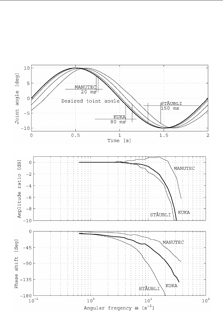
First, one very simple experiment will show the differences in robot dynamics caused
mainly by robot controllers. The desired joint angle of joint No. 1 is commanded by the
sinusoidal signal with the amplitude of 10deg and the period time of 2s. The current joint
angle values were recorded for every of the three robot systems. The lag between desired
and current joint angle time curves is shown in Fig. 7 and may be analyzed.
It can be seen that the maximum phase shift occurs with the STÄUBLI robot system where
the desired position was sent to the trajectory generator via motion commands for joint
interpolation. To get this sinusoidal series the motion was divided into a lot of small parts
and the mode of the continuous motion was used. Having access to the desired values of the
joint position control loops may reduce the phase shift. An example is the KUKA robot
controller programmed by RSI. The minimum phase shift can be reached if it is possible to
design the control loops individually which can be seen e.g. with the WinDDC-Real-Time-
Controller connected to the robot MANUTEC r3. However, for this purpose only a simple
proportional controller with additional feed forward control of the desired joint velocity was
implemented. To get more information about the dynamics of the different robot systems
the frequency responses were recorded. Their amplitude and phase responses are shown in
Fig. 8. It can be seen that the system dynamics depends decisively on the level of motion
generation. If the level is low the bandwidth will be high. It has to be taken into
consideration while specifying the parameters of the desired impedance behaviour. Its
bandwidth should be lower then the bandwidth of the robot to guarantee following the
desired impedance behaviour.
4. Sensorless force based human robot interaction
The algorithms and features of force based human robot interaction presented in the
previous section require that the robot is equipped with a 6D F/T sensor. The cost of such a
sensor is of the order of some thousand Euros at present. Therefore, it would be favourable
to find a way to do without F/T sensor. One possibility is to estimate the interaction forces
and torques from the motor currents.
Human-Robot Interaction
458
4.1 Estimation of interaction forces and torques
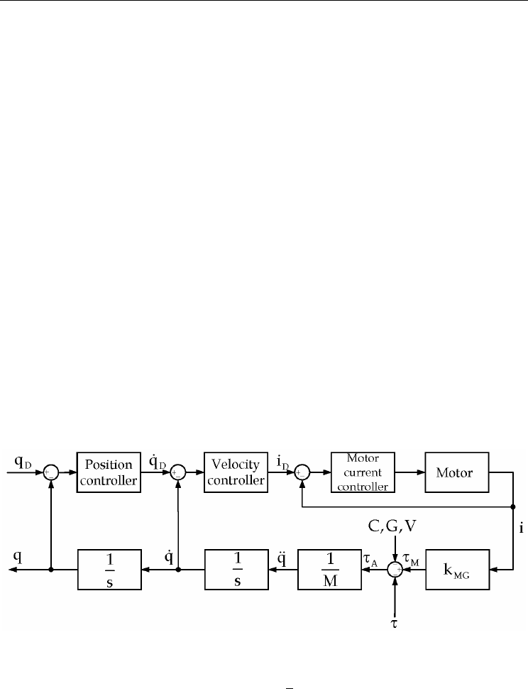
Most commonly used robots are driven by AC servo motors. Fig. 9 shows the signal flow
diagram of single joint which is position controlled in cascade control mode.
The position controller is a proportional controller whereas velocity and motor current are
controlled by proportional plus integral controllers. The electrical time constant of the motor
is very small in comparison to the mechanical response time. It will be assumed that there
are no losses due to magnetisation and internal friction. Hence, there is a linear dependency
between motor current i and joint driving torque τ
M
determined by motor constant k
M
and
gear ratio k
G
(k
MG
=k
M
k
G
). Besides the driving torque acting in the joint, robot is also
influenced by Coriolis and centrifugal torque C, gravitational torque G, frictional torque V
and the interaction torque τ caused by the operator or the environment. The joint
acceleration torque τ
A
is given according to (19):
τ−−−−⋅=τ VGCik
MGA
(19)
Assuming the response time of the motor current control loop is very small and its static
control error goes to zero due to the proportional plus integral controller structure, for the
calculation of the interaction torque τ the desired value of the motor current i
D
can be used
instead of its current value i. The joint torque τ
A
accelerates the particular robot link taking
its inertia M into consideration. For operator security the velocity and acceleration values of
all joints have to be small. As a result the joint torque and the Coriolis/centrifugal torque
may be neglected. The interaction torque can then be approximately calculated as follows:
VGik
DMG
−−⋅=τ
(20)
Figure 9. Signal flow diagram of one joint
To perform this calculation it is necessary to learn the vector of the gravitational torques of
the robot. It is a function of the joint angle vector q
and can be calculated from the dynamic
model of the robot. The dynamic models of some manipulator arms are published, see e.g.
(Türk & Otter, 1987) for the model of robot MANUTEC r3. The calculation of the frictional
torques is difficult. Friction is speed dependent consisting of Coulomb friction, stiction and
speed proportional friction. Furthermore, the particular friction components are dependent
Possibilities of force based interaction with robot manipulators
459
e.g. on position, temperature and aging of the robot. Especially at low velocity motions
where Coulomb friction and stiction are dominant it is very difficult to calculate feasible
values and at robot standstill it is nearly impossible because of the PI-structure of the
velocity controller the portion of Coulomb friction and stiction can not be separated from
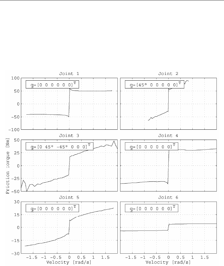
the motor current. An example of robot joint friction is shown in Fig. 10. Here the robot
MANUTEC r3 was used. It was equipped with the WinDDC-Real-Time-Controller
mentioned earlier in section 3 (Winkler & Suchý, 2005). The desired values of motor currents
are provided by the joint power amplifiers via analogue voltages which are connected to the
analogue inputs of the robot controller for signal processing according to Eq. (20).
Figure 10. Joint friction torques determined for a robot of type MANUTEC r3
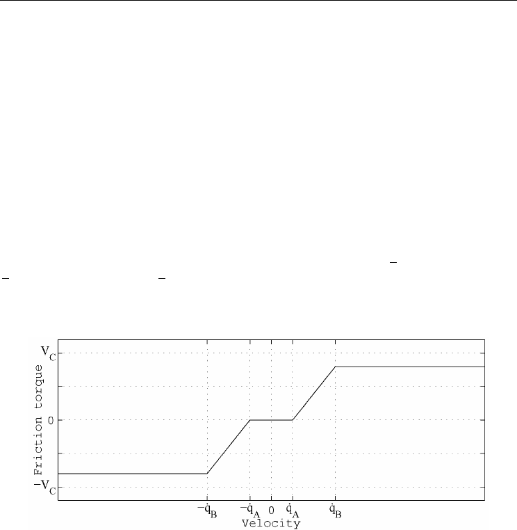
Fig. 10 shows clearly that during low velocity motion generated future by force based
human robot interaction stiction and Coulomb friction are prevailing. Therefore, the
proposed model for friction estimation is simplified to the form in Fig. 11. It consists of the
dead zone nonlinearity in the neighbourhood of robot standstill described by velocity
parameter q
’
A
to prevent oscillations. In the range between q
’
A
and q
’
B
the friction increases
to its maximum value V
c
. When computing friction torques for the estimation of the
Human-Robot Interaction
460
interaction torques it is absolutely necessary to avoid the case that the value of any
estimated friction torque is higher than its real value. Otherwise it may be happen that the
force guided robot becomes unstable during human robot interaction which could be a very
dangerous situation to the operator.
Verification of the proposed algorithm to estimate the interaction torques of an industrial
robot from its motor currents was performed on the MANUTEC r3 robot equipped with the
open WinDDC-Real-Time-Controller. For comparison of the estimated values with the real
interaction forces/torques 6D-F/T sensor was additional mounted into robot wrist. For that
reason the operator should touch the robot only on its end-effector behind the sensor.
Pushing and polling the robot on its links would result in faulty measurements. However, it
is also possible to guide the robot by means of motor currents when the operator acts on
arbitrary location of the manipulator arm. The comparison is performed in joint space. From
the interaction forces and torques measured by F/T sensor the corresponding joint torques
can be computed using the transposed Jacobian matrix, see e.g. (5). Different postures of the
robot arm were chosen to validate the estimation of the gravitational torques from the
dynamic model. They are described by the joint angle vectors q
A
=[0 0 90° 0 0 0]
T
,
q
B
=[-30° 45° 30° 0 0 0]
T
and q
C
=[0 0 90° 0 -90° 0]
T
. The operator acted in a random way with
forces and torques on the robot end-effector for a certain time period and the time series of
actual and estimated interaction joint torques were recorded. They are compared in Fig. 12.
Figure 11. Proposal of friction torque model at low joint velocities
Because the signals which represent the desired motor currents sent from the velocity
control loops to the motor current control loops are noisy, they have to be low pass filtered
before signal processing. For this purpose a first order system was used which results in a
time lag between the plot of the estimated time series and the measured time series.
Furthermore, some more differences can be seen. They may result from inaccuracies of the
dynamic model of the robot used for the calculation of the gravitational torques. Another
source of error comes from the frictional torques. It was already mentioned that during
robot standstill the proportional plus integral joint velocity controller outputs a control
signal within the range of stiction. This motor current therefore is not able to generate a
motion and may be misunderstood as interaction torque. This effect is shown in Fig. 12, e.g.
in joint No. 1 when the robot is located at posture A.