Short T.A. Electric Power Distribution Handbook
Подождите немного. Документ загружается.


124 Electric Power Distribution Handbook
TABLE 3.16
Impedances of Single-Conductor Copper Power Cables
Conductor Size R
1
X
1
R
0
X
0
R
S
X
S
Flat spacing with a 7.5-in. separation
2 0.2083 0.1029 0.5108 0.4401 0.3092 0.2153
1 0.1671 0.0991 0.4718 0.4267 0.2687 0.2083
1/0 0.1334 0.0965 0.4405 0.4115 0.2358 0.2015
2/0 0.1082 0.0938 0.4171 0.3967 0.2112 0.1948
3/0 0.0871 0.0911 0.3975 0.3794 0.1906 0.1872
4/0 0.0705 0.0884 0.3816 0.3626 0.1742 0.1798
250 0.0607 0.0862 0.3719 0.3471 0.1644 0.1732
350 0.0461 0.0823 0.3558 0.3181 0.1493 0.1609
500 0.0352 0.0782 0.3411 0.2891 0.1372 0.1485
750 0.0272 0.0732 0.3241 0.2490 0.1261 0.1318
1000 0.0234 0.0699 0.3104 0.2196 0.1191 0.1198
Triplex
2 0.2032 0.0508 0.5707 0.4642 0.3257 0.1886
1 0.1619 0.0477 0.5301 0.4480 0.2846 0.1811
1/0 0.1281 0.0460 0.4966 0.4295 0.2509 0.1738
2/0 0.1028 0.0442 0.4709 0.4116 0.2255 0.1667
3/0 0.0816 0.0426 0.4485 0.3910 0.2039 0.1587
4/0 0.0649 0.0409 0.4299 0.3713 0.1866 0.1510
250 0.0551 0.0398 0.4175 0.3532 0.1759 0.1442
350 0.0403 0.0377 0.3962 0.3202 0.1589 0.1319
500 0.0292 0.0355 0.3765 0.2882 0.1450 0.1197
750 0.0211 0.0333 0.3524 0.2450 0.1315 0.1039
1000 0.0173 0.0322 0.3336 0.2142 0.1227 0.0929
Note: Impedances, W/1000 ft (¥ 5.28 for W/mi or ¥ 3.28 for W/km). Resis-
tances for a conductor temperature = 90∞C and a shield temperature
= 50∞C, 220-mil insulation (15 kV), r = 100 W-m, 5-mil copper tape
shield with a lap of 20%.
TABLE 3.17
Cable Capacitance for Common Cable Sizes and Voltages
Size
Capacitance, mF/1000 ft Reactive power, kvar/1000 ft
175 mil 220 mil 260 mil 345 mil
12.5 kV
175 mil
12.5 kV
220 mil
25 kV
260 mil
34.5 kV
345 mil
2 0.0516 0.0441 0.0396 0.0333 1.01 0.862 3.09 4.98
1 0.0562 0.0479 0.0428 0.0358 1.1 0.936 3.35 5.35
1/0 0.0609 0.0516 0.046 0.0383 1.19 1.01 3.6 5.72
2/0 0.0655 0.0553 0.0492 0.0407 1.28 1.08 3.84 6.09
3/0 0.0712 0.0599 0.0531 0.0437 1.39 1.17 4.15 6.54
4/0 0.078 0.0654 0.0578 0.0473 1.52 1.28 4.52 7.08
250 0.0871 0.0727 0.064 0.0521 1.7 1.42 5.00 7.79
350 0.0995 0.0826 0.0725 0.0586 1.94 1.61 5.67 8.76
500 0.113 0.0934 0.0817 0.0656 2.21 1.83 6.38 9.81
750 0.135 0.111 0.0969 0.0772 2.65 2.18 7.57 11.5
1000 0.156 0.127 0.111 0.0875 3.04 2.49 8.64 13.1
Note: For XLPE cable with e = 2.3.
1791_book.fm Page 124 Monday, August 4, 2003 3:20 PM
(C) 2004 by CRC Press LLC

Und
recommended maximum temperature. Cross-linked polyethylene cables are
rated for a maximum operating temperature of 90∞C during normal opera-
tions. Operating cables above their ampacity increases the likelihood of
premature failures: water trees may grow faster, thermal runaway-failures
are more likely, and insulation strength may decrease. In addition to absolute
temperature, thermal cycling also ages cable more quickly.
Ampacity most often limits the loading on a cable; rarely, voltage drop or
flicker limits loadings. Relative to overhead lines, cables of a given size have
lower impedance and lower ampacities. So cable circuits are much less likely
than overhead circuits to be voltage-drop limited. Only very long cable runs
on circuits with low primary voltages are voltage-drop limited. Ampacity is
not the only consideration for cable selection; losses and stocking consider-
ations should also factor into cable selection. Choosing the smallest cable
that meets ampacity requirements has the lowest initial cost, but since the
cable is running hotter, the cost over its life may not be optimal because of
the losses. Also allow for load growth when selecting cables.
Ampacity calculations follow simple principles: the temperature at the
conductor is a function of the heat generated in a cable (I
2
R) and the amount
of heat conducted away from the cable. We can model the thermal perfor-
mance with a thermal circuit analogous to an electric circuit: heat is analo-
gous to current; temperature to voltage; and thermal resistance to electrical
resistance. Heat flow through a thermal resistance raises the temperature
between the two sides of the thermal material. Higher resistance soils or
insulations trap the heat and cause higher temperatures. Using the thermal
equivalent of Ohm’s law, the temperature difference is:
where
T
C
= conductor temperature,
∞
C
T
A
= ambient earth temperature,
∞
C
R
TH
= total thermal resistance between the cable conductor and the air,
thermal W-ft
H = heat generated in the cable, W ( = I
2
R)
I = electric current in the conductor, A
R = electric resistance of the conductor, W/ft
Most ampacity tables and computer calculation routines are based on the
classic paper by Neher and McGrath (1957). The original paper is an excellent
reference. Ander’s book (1998) provides a detailed discussion of cable
ampacity calculations, including the Neher–McGrath method along with
IEC’s method that is very similar (IEC 287, 1982). Hand calculations or
spreadsheet calculations of the Neher–McGrath equations are possible, but
tiresome; while straightforward in principle, the calculations are very
detailed. A review of the Neher–McGrath procedure — the inputs, the tech-
DTT T RHR IR
CA TH TH
=-= = ()
2
1791_book.fm Page 125 Monday, August 4, 2003 3:20 PM
(C) 2004 by CRC Press LLC
126 Electric Power Distribution Handbook
niques, the assumptions — provides a better understanding of ampacity
calculations to better use computer ampacity calculations.
The Neher–McGrath procedure solves for the current in the equation
above. Figure 3.9 shows a simplified model of the thermal circuit. The two
main sources of heat within the cable are the I
2
R losses in the phase conductor
and the I
2
R losses in the neutral or shield. The cable also has dielectric losses,
but for distribution-class voltages, these are small enough that we can neglect
them. The major thermal resistances are the insulation, the jacket, and the
earth. If the cable system is in a duct, the air space within the duct and the
duct walls adds thermal resistance. These thermal resistances are calculated
from the thermal resistivities of the materials involved. For example, the
thermal resistance of the insulation, jacket, and duct wall are all calculated
with an equation of the following form:
where
R = thermal resistance of the component, thermal W-ft
r = thermal resistivity of the component material, ˚C-cm/W
D = outside diameter of the component
d = inside diameter of the component
Thermal resistivity quantifies the insulating characteristics of a material.
A material with r = 1∞C-cm/W has a temperature rise of 1˚C across two
sides of a 1-cm
3
cube for a flow of one watt of heat through the cube. As
with electrical resistivity, the inverse of thermal resistivity is thermal con-
ductivity. Table 3.18 shows resistivities commonly used for cable system
components. The thermal resistance of a material quantifies the radial tem-
perature rise from the center outward. One thermal W-ft has a radial tem-
perature rise of 1˚C for a heat flow of 1 W per ft of length (length along the
conductor). Mixing of metric (SI) units with English units comes about for
historical reasons.
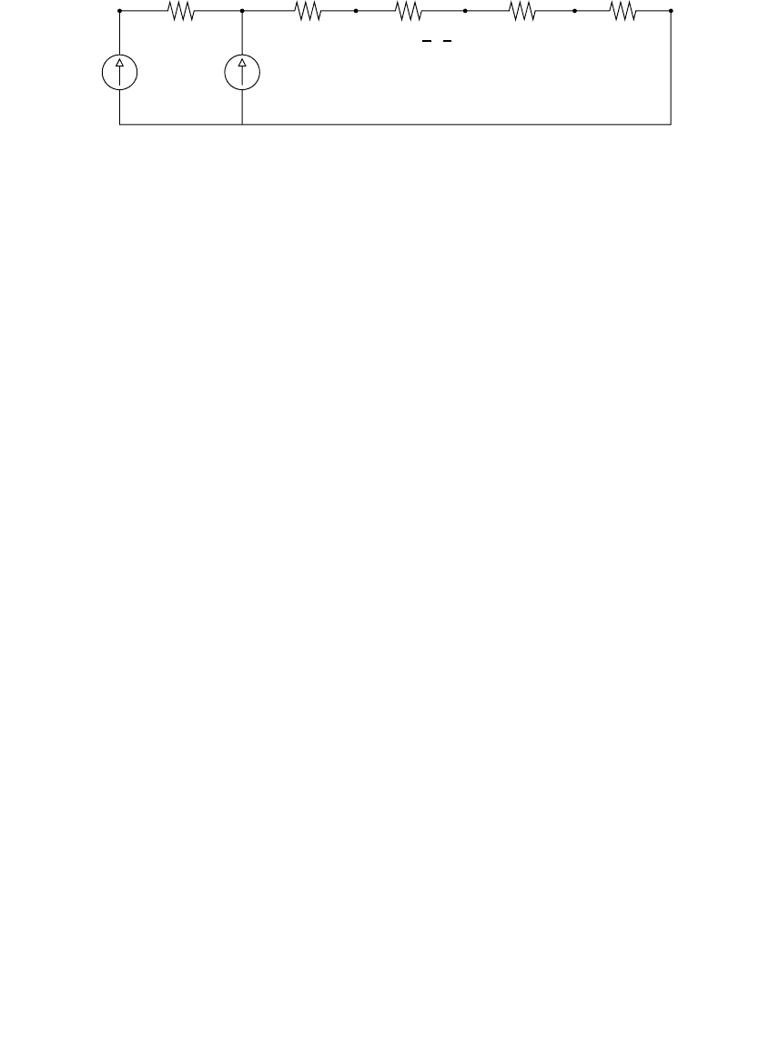
FIGURE 3.9
Thermal circuit model of a cable for ampacity calculations.
Conductor
losses
Shield/neutral
losses
T
c
T
earth
R
insulation
R
jacket
R
cable to duct
R
ductwall
R
earth
I
2
RI
2
s
R
s
RDd= 0 012
10
. log ( / )r
1791_book.fm Page 126 Monday, August 4, 2003 3:20 PM
(C) 2004 by CRC Press LLC

The Neher–McGrath calculations also account for multiple cables, cables
with cyclic daily load cycles, external heat sources, duct arrangements, and
shield resistance and grounding variations.
Often, the easiest way to find ampacities for a given application is with
ampacity tables. Table 3.19 and Table 3.20 show ampacities for common
distribution configurations. Of the many sources of ampacity tables, the IEEE
publishes the most exhaustive set of tables (IEEE Std. 835-1994). The National
Electrical Code (NFPA 70, 1999) and manufacturer’s publications (Okonite,
1990; Southwire Company, 1997) are also useful. Ampacity tables provide a
TABLE 3.18
Thermal Resistivities of Common Components
Component
Thermal Resistivity,
∞∞
∞∞
C-cm/W
XLPE insulation 350
EPR insulation 500
Paper insulation 700
PE jackets 350
PVC jackets 500
Plastic ducts 480
Concrete 85
Thermal fill 60
Soil 90
Water 160
Air 4000
Sources: IEC 287, Calculation of the Continuous Current
Rating of Cables (100% Load Factor), 2nd ed., Interna-
tional Electrical Commission (IEC), 1982; Neher, J. H.
and McGrath, M. H., “The Calculation of the Temper-
ature Rise and Load Capability of Cable Systems,”
AIEE Transactions, vol. 76, pp. 752–64, October 1957.
TABLE 3.19
Ampacities of Single-Phase Circuits of
Full-Neutral Aluminum Conductor Cables
Size
Direct Buried
Load Factor
In Conduit
Load Factor
100% 75% 100% 75%
2 187 201 146 153
1 209 225 162 170
1/0 233 252 180 188
2/0 260 282 200 210
3/0 290 316 223 234
4/0 325 356 249 262
250 359 395 276 291
350 424 469 326 345
Note: 90˚C conductor temperature, 25˚C ambi-
ent earth temperature, r = 90∞C-cm/W.
1791_book.fm Page 127 Monday, August 4, 2003 3:20 PM
(C) 2004 by CRC Press LLC

128 Electric Power Distribution Handbook
good starting point for determining the ampacity of a specific cable appli-
cation. When using tables, be careful that the assumptions match your par-
ticular situation; if not, ampacity results can be much different than expected.
Conductor temperature limits, sheath resistance, thermal resistivity of the
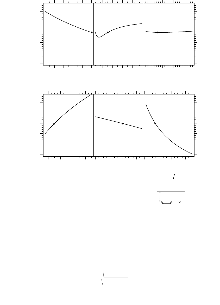
soil — these are some of the variables that most impact ampacity (see Figure
3.10). These and other effects are discussed in the next few paragraphs [see
also (CEA, 1982; NRECA RER Project 90-8, 1993) for more discussions].
Sheath resistance — On a three-phase circuit, the resistance of the sheath
(or shield or neutral) plays an important role in ampacity calculations.
Because a cable’s phase conductor and sheath couple so tightly, current
through the phase induces a large voltage along the sheath. With the cable
sheath grounded periodically, circulating current flows to counter the
induced voltage. The circulating current is a function of the resistance of the
sheath. This circulating current leads to something counterintuitive: sheaths
with higher resistance have more ampacity. Higher resistance sheaths reduce
the circulating current and reduce the I
2
R losses in the sheath. This effect is
TABLE 3.20
Ampacities of Three-Phase Circuits Made
of Single-Conductor, One-Third Neutral
Aluminum Cables
Size
Direct Buried
Load factor
In Conduit
Load factor
100% 75% 100% 75%
Flat spacing (7.5-in. separation)
1/0 216 244 183 199
2/0 244 277 207 226
3/0 274 312 233 255
4/0 308 352 262 287
250 336 386 285 315
350 392 455 334 370
500 448 525 382 426
750 508 601 435 489
1000 556 664 478 541
Triplex
1/0 193 224 158 173
2/0 220 255 180 197
3/0 249 290 204 225
4/0 283 330 232 256
250 312 365 257 284
350 375 442 310 345
500 452 535 375 419
750 547 653 457 514
1000 630 756 529 598
Note: 90˚C conductor temperature, 25˚C ambi-
ent earth temperature, r = 90∞C-cm/W.
1791_book.fm Page 128 Monday, August 4, 2003 3:20 PM
(C) 2004 by CRC Press LLC
most pronounced in larger conductors. Many ampacity tables assume that
cable sheaths are open circuited, this eliminates the sheath losses and
increases the ampacity. The open-circuit sheath values can be approximately
corrected to account for circulating currents (Okonite, 1990) by
FIGURE 3.10
Effect of variables on ampacity for an example cable.
Ampacity, amperes
0.5 0.7 0.9
300 400 500
Loss factor
246810
Shield resistance in
multiples of phase resistance
Spacing, inches
5101520
80 100 120 140
300 400 500
Conductor temp.
°C
Ampacity, amperes
Soil temp.
°C
15 20 25 30 50 100 150 200
Earth thermal resistivity
°C-cm
W
500 kcmil aluminum, 15-kV, 220-mil insulation
1/3 neutral, direct buried, jacketed, load factor = 1
r
earth
= 90
◦
C-cm/W, r
insulation
= r
jacket
= 400
◦
C-cm/W
T
c
= 90
◦
C, T
earth
= 25
◦
C
7.5 in
36 in
k
IR
IR IR
SS
=
+
2
22
1791_book.fm Page 129 Monday, August 4, 2003 3:20 PM
(C) 2004 by CRC Press LLC

130 Electric Power Distribution Handbook
where
k = ampacity multiplier to account for sheath losses, i.e., I
grounded sheath
=
k · I
open sheath
I = phase conductor current, A
I
S
= sheath current, A
I
2
R = phase conductor losses, W/unit of length
I
S
2
R
S
= sheath losses, W/unit of length
The sheath losses are a function of the resistance of the sheath and the
mutual inductance between the sheath and other conductors. For a triangular
configuration like triplex, the shield losses are
where
and
X
M
= mutual inductance of the sheath and another conductor, mW/1000 ft
R
S
= resistance of the sheath, mW/1000 ft
f = frequency, Hz
S = spacing between the phase conductors, in.
d
S
= mean diameter of the sheath, in.
For configurations other than triplex, see Southwire Company (1997) or
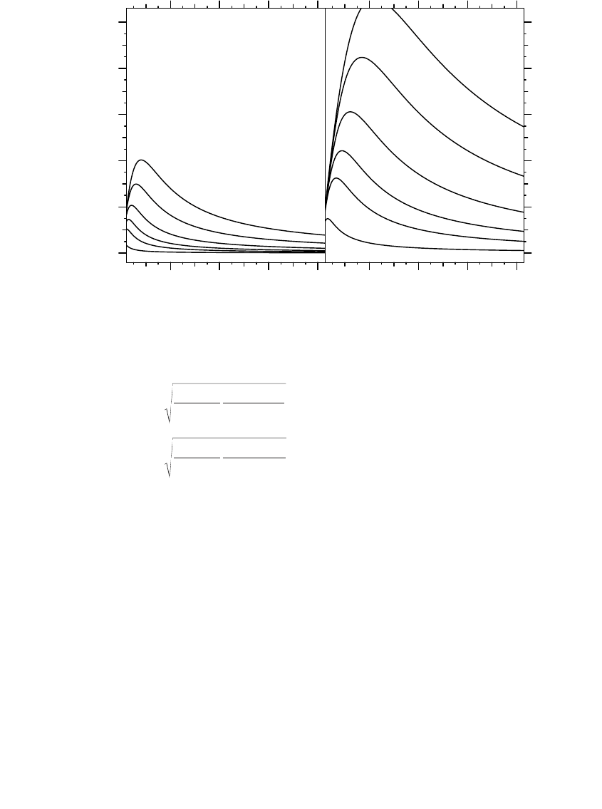
Okonite (1990). Figure 3.11 shows how sheath losses vary with conductor
size and with spacing. Spacing has a pronounced effect. Steel ducts can
significantly increase heating from circulating currents. In fact, even nearby
steel pipes can significantly reduce ampacity.
Spacings — Separating cables separates the heat sources. But at larger
spacings, circulating currents are higher. Optimal spacings involve balancing
these effects. For smaller cables, separating cables provides the best ampacity.
For larger cables (with larger circulating currents), triplex or other tight
spacing improves ampacity. For one-third neutral, aluminum cables, NRECA
(1993) shows that a flat spacing with 7.5 in between cables has better ampac-
ity than triplex for conductors 500 kcmil and smaller. For copper cables, the
threshold is lower: conductors larger than 4/0 have better ampacity with a
triplex configuration.
Conductor temperature — If we allow a higher conductor temperature, we
can operate a cable at higher current. If we know the ampacity for a given
conductor temperature, at a different conductor temperature we can find the
ampacity with the following approximation:
IR IR
X
RX
SS S
M
SM
22
2
22
=
+
Xf Sd
MS
= 201404 2
10
p (. )log ( / )
1791_book.fm Page 130 Monday, August 4, 2003 3:20 PM
(C) 2004 by CRC Press LLC
Underground Distribution 131
where
I' = ampacity at a conductor temperature of T
C
¢ and an ambient earth tem-
perature T
A
¢
I = ampacity at a conductor temperature of T
C
and an ambient earth tem-
perature T
A
(all temperatures are in ∞C)
We can use these equations to find emergency ampacity ratings of cables.
In an emergency, XLPE can be operated to 130∞C. Some EPR cables can be
operated to 140∞C (MV-105 cables). ICEA standards allow emergency over-
load for 100 hours per year with five such periods over the life of the cable.
Polyethylene cables, including HMWPE, have little overload capability.
Their maximum recommended emergency temperature is 95∞C. Table 3.21
shows common ampacity multipliers; these are valid for both copper and
aluminum conductors within the accuracy shown. We can also use the appro-
FIGURE 3.11
Shield losses as a function of shield resistance for aluminum cables (triplex configuration).
2468
020406080100
A
B
C
D
E
F
A
B
C
D
E
F
:
:
:
:
:
:
1000 kcmil
750 kcmil
500 kcmil
350 kcmil
250 kcmil
1/0
Shield resistance in
multiples of phase resistance
Shi
e
ld
l
osses
i
n percent
of phase losses
triplex spacing
2468
020406080100
A
B
C
D
E
F
Shield resistance in
multiples of phase resistance
7.5-inch spacing
2468
¢
=
¢
-
¢
-
+
+
¢
¢
=
¢
-
¢
-
+
+
¢
II
TT
TT
T
T
II
TT
TT
T
T
CA
CA
C
C
CA
CA
C
C
228 1
228 1
234 5
234 5
.
.
.
.
(
(Aluminum conductor)
Copper conductor)
1791_book.fm Page 131 Monday, August 4, 2003 3:20 PM
(C) 2004 by CRC Press LLC

132 Electric Power Distribution Handbook
priate temperature-adjustment equation to adjust for different ambient earth
temperatures.
Loss factor — The earth has a high thermal storage capability; it takes
considerable time to heat (or cool) the soil surrounding the cable. Close to
the cable, the peak heat generated in the cable determines the temperature
drop; farther out, the average heat generated in the cable determines the
temperature drop. As discussed in Chapter 5, we normally account for
losses using the loss factor, which is the average losses divided by the peak
losses. Since this number is not normally available, we find the loss factor
from the load factor (the load factor is the average load divided by the peak
load). Assuming a 100% load factor (continuous current) is most conserva-
tive but can lead to a cable that is larger than necessary. We should try to
err on the high side when estimating the load factor. A 75% load factor is
commonly used.
Conduits — The air space in conduits or ducts significantly reduces ampac-
ity. The air insulation barrier traps more heat in the cable. Direct-buried
cables may have 10 to 25% higher ampacities. Although, the less air the
better, there is little practical difference in the thermal performance between
the sizes of ducts commonly used. Concrete duct banks have roughly the
same thermal performance as direct-buried conduits (concrete is more con-
sistent and less prone to moisture fluctuations).
Soil thermal resistivity and temperature — Soils with lower thermal resistivity
more readily conduct heat away from cables. Moisture is an important
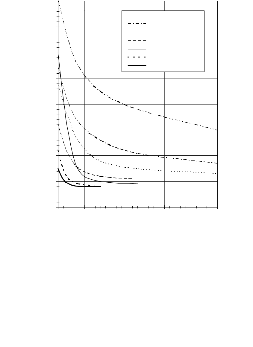
component, moist soil has lower thermal resistivity (see Figure 3.12). Dense
soil normally has better conductivity. More so than any other single factor,
soil resistivity impacts the conductor’s temperature and the cable’s ampac-
ity. A resistivity of 90∞C-cm/W is often assumed for ampacity calculations.
This number is conservative enough for many areas, but if soil resistivities
are higher, cable temperatures can be much higher than expected. For com-
mon soils, Table 3.22 shows typical ranges of thermal resistivities. At typical
installation depths, resistivity varies significantly with season as moisture
content changes. Unfortunately in many locations, just when we need
ampacity the most — during peak load in the summer — the soil is close
to its hottest and driest. Seasonal changes can be significant, but daily
TABLE 3.21
Common Ampacity Rating Conversions (with T
A
= 25∞∞
∞∞
C)
Original Temperature,
∞C
New Temperature,
∞C Ampacity Multiplier
75 95 1.15
90 75 0.90
90 105 1.08
90 130 1.20
105 140 1.14
1791_book.fm Page 132 Monday, August 4, 2003 3:20 PM
(C) 2004 by CRC Press LLC
Underground Distribution 133
changes are not; soil temperature changes lag air temperature changes by 2
to 4 weeks.
The depth of burial can affect ampacity. With a constant resistivity and
soil temperature, deeper burial decreases ampacity. But deeper, the soil tends
to have lower temperature, more moisture, and soil is more stable seasonally.
To go deep enough to take advantage of this is not cost effective though.
For areas with poor soil (high clay content in a dry area, for example),
one of several thermal backfills can give good performance, with stable
FIGURE 3.12
Effect of moisture on the thermal resistivity of various soils. (Copyright © 1997. Electric Power
Research Institute. TR-108919. Soil Thermal Properties Manual for Underground Power Transmission.
Reprinted with permission.)
0
50
100
150
200
250
300
350
400
051015 20 25 30
Moisture Content (% by dry weight)
Thermal Resistivity (
o
C-cm/W)
Soft Organic Clay
Clay
Silt
Silty Sand with Gravel
Uniform Sand
Stone Screenings
FTB
1791_book.fm Page 133 Monday, August 4, 2003 3:20 PM
(C) 2004 by CRC Press LLC