Simmons C.H., Dennis E.M. Manual of Engineering Drawing
Подождите немного. Документ загружается.

Every article used in our day-to-day lives will probably
have been produced as a result of solutions to a sequence
of operations and considerations, namely:
1 Conception
2 Design and analysis
3 Manufacture
4 Verification
5 Disposal.
The initial stage will commence when an original
marketable idea is seen to have a possible course of
development. The concept will probably be viewed
from an artistic and a technological perspective.
The appearance and visual aspects of a product are
very important in creating an acceptable good first
impression.
The technologist faces the problem of producing
a sound, practical, safe design, which complies with
the initial specification and can be produced at an
economical cost.
During every stage of development there are many
progress records to be maintained and kept up to date
so that reference to the complete history is available to
responsible employees.
For many years various types of drawings, sketches
and paintings have been used to convey ideas and
information. A good recognizable picture will often
remove ambiguity when discussing a project and assist
in overcoming a possible language barrier.
British Standards are listed in the British Standards
Catalogue and the earliest relevant Engineering
Standards date back to 1903. Standards were developed
to establish suitable dimensions for a range of sizes of
metal bars, sheets, nuts, bolts, flanges, etc. following
the Industrial Revolution and used by the Engineering
Industry. The first British Standard for Engineering
Drawing Office Practice published in September 1927
only contained 14 clauses as follows:
1 Sizes of drawings and tracings, and widths of
tracing cloth and paper
2 Position of drawing number, date and name
3 Indication of scale
4 Method of projection
5 Types of line and writing
6 Colour of lines
7 Dimension figures
8 Relative importance of dimensions
9 Indication of materials on drawings
10 Various degrees of finish
11 Screw threads
12 Flats and squares
13 Tapers
14 Abbreviations for drawings.
There were also five figures illustrating:
1 Method of projection
2 Types of line
3 Views and sections
4 Screw threads
5 Tapers.
First angle projection was used for the illustrations
and the publication was printed on A5 sheets of paper.
During the early days of the industrial revolution
manufacturers simply compared and copied component
dimensions to match those used on the prototype.
However, with the introduction of quantity production
where components were required to be made at different
factory sites, measurement by more precise means was
essential. Individual manufacturers developed their own
standard methods. Clearly, for the benefit of industry
in general a National Standard was vital. Later the
more comprehensive British Standard of Limits and
Fits was introduced. There are two clear aspects, which
are necessary to be considered in the specification of
component drawings:
1 The drawing shows the dimensions for the
component in three planes. Dimensions of the
manufactured component need to be verified because
some variation of size in each of the three planes
(length, breadth and thickness) will be unavoidable.
The Designers contribution is to provide a
Characteristics Specification, which in current jargon
is defined as the ‘Design Intent Measurand’.
2 The metrologist produces a ‘Characteristics
Evaluation’ which is simply the Measured Value.
The drawing office is generally regarded as the heart
of any manufacturing organization. Products,
components, ideas, layouts, or schemes which may be
Chapter 1
Drawing office management and
organization
2 Manual of Engineering Drawing
presented by a designer in the form of rough freehand
sketches, may be developed stage by stage into working
drawings by the draughtsman. There is generally very
little constructive work which can be done by other
departments within the firm without an approved
drawing of some form being available. The drawing is
the universal means of communication.
Drawings are made to an accepted standard, and in
this country, is BS 8888, containing normative and
informative references to international standards. These
standards are acknowledged and accepted throughout
the world.
The contents of the drawing are themselves, where
applicable, in agreement with separate standards relating
to materials, dimensions, processes, etc. Larger
organizations employ standards engineers who ensure
that products conform to British and also international
standards where necessary. Good design is often the
product of teamwork where detailed consideration is
given to the aesthetic, economic, ergonomic and
technical aspects of a given problem. It is therefore
necessary to impose the appropriate standards at the
design stage, since all manufacturing instructions
originate from this point.
A perfect drawing communicates an exact
requirement, or specification, which cannot be
misinterpreted and which may form part of a legal
contract between supplier and user.
Engineering drawings can be produced to a good
professional standard if the following points are
observed:
(a) the types of lines used must be of uniform
thickness and density;
(b) eliminate fancy printing, shading and associated
artistry;
(c) include on the drawing only the information which
is required to ensure accurate clear com-
munication;
(d) use only standard symbols and abbreviations;
(e) ensure that the drawing is correctly dimensioned
(adequately but not over-dimensioned) with no
unnecessary details.
Remember that care and consideration given to small
details make a big contribution towards perfection,
but that perfection itself is no small thing. An accurate,
well delineated engineering drawing can give the
draughtsman responsible considerable pride and job
satisfaction.
The field of activity of the draughtsman may involve
the use, or an appreciation, of the following topics.
1 Company communications Most companies have
their own systems which have been developed over
a period of time for the following:
(a) internal paperwork,
(b) numbering of drawings and contracts,
(c) coding of parts and assemblies,
(d) production planning for component manufac-
ture,
(e) quality control and inspection,
(f) updating, modification, and reissuing of
drawings.
2 Company standards Many drawing offices use
their own standard methods which arise from
satisfactory past experience of a particular product
or process. Also, particular styles may be retained
for easy identification, e.g. certain prestige cars
can be recognized easily since some individual
details, in principle, are common to all models.
3 Standards for dimensioning Interchangeability and
quality are controlled by the application of practical
limits, fits and geometrical tolerances.
4 Material standards Physical and chemical
properties and non-destructive testing methods must
be borne in mind. Note must also be taken of
preferred sizes, stock sizes, and availability of rod,
bar, tube, plate, sheet, nuts, bolts, rivets, etc. and
other bought-out items.
5 Draughting standards and codes of practice
Drawings must conform to accepted standards, but
components are sometimes required which in
addition must conform to certain local requirements
or specific regulations, for example relating to safety
when operating in certain environments or
conditions. Assemblies may be required to be
flameproof, gastight, waterproof, or resistant to
corrosive attack, and detailed specifications from
the user may be applicable.
6 Standard parts are sometimes manufactured in
quantity by a company, and are used in several
different assemblies. The use of standard parts
reduces an unnecessary variety of materials and
basically similar components.
7 Standards for costs The draughtsman is often
required to compare costs where different methods
of manufacture are available. A component could
possible be made by forging, by casting, or by
fabricating and welding, and a decision as to which
method to use must be made. The draughtsman
must obviously be well aware of the manufacturing
facilities and capacity offered by his own company,
the costs involved when different techniques of
production are employed, and also an idea of the
likely costs when work is sub-contracted to specialist
manufacturers, since this alternative often proves
an economic proposition.
8 Data sheets Tables of sizes, performance graphs,
and conversion charts are of considerable assistance
to the design draughtsman.
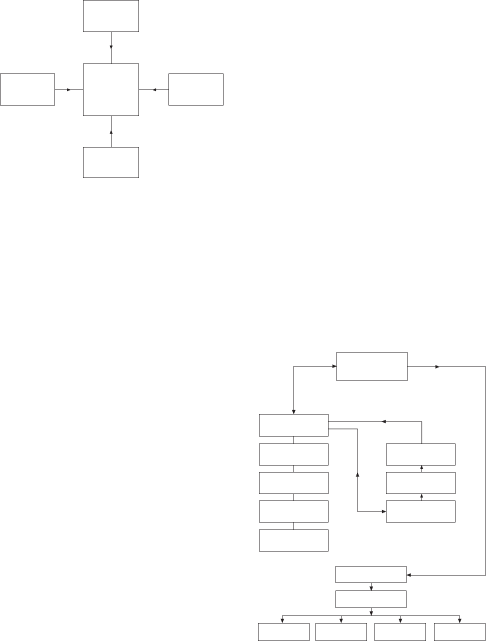
Figure 1.1 shows the main sources of work flowing
into a typical industrial drawing office. The drawing
office provides a service to each of these sources of
supply, and the work involved can be classified as
follows.
1 Engineering The engineering departments are
engaged on
(a) current production;
Drawing office management and organization 3
(b) development;
(c) research;
(d) manufacturing techniques, which may include
a study of metallurgy, heat-treatment, strength
of materials and manufacturing processes:
(e) advanced project planning;
(f) field testing of products.
2 Sales This department covers all aspects of
marketing existing products and market research
for future products. The drawing office may receive
work in connection with
(a) general arrangement and outline drawings for
prospective customers;
(b) illustrations, charts and graphs for technical
publications;
(c) modifications to production units to suit
customers’ particular requirements;
(d) application and installation diagrams;
(e) feasibility investigations.
3 Service The service department provides a reliable,
prompt and efficient after-sales service to the
customer. The drawing office receives work
associated with
(a) maintenance tools and equipment;
(b) service kits for overhauls;
(c) modifications to production parts resulting from
field experience;
(d) service manuals.
4 Manufacturing units Briefly, these cover all
departments involved in producing the finished end-
product. The drawing office must supply charts,
drawings, schedules, etc. as follows:
(a) working drawings of all the company’s
products;
(b) drawings of jigs and fixtures associated with
manufacture;
(c) plant-layout and maintenance drawings;
(d) modification drawings required to aid
production;
(e) reissued drawings for updated equipment;
(f) drawings resulting from value analysis and
works’ suggestions.
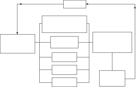
Figure 1.2 shows the organization in a typical drawing
office. The function of the chief draughtsman is to
take overall control of the services provided by the
office. The chief draughtsman receives all work coming
into the drawing office, which he examines and
distributes to the appropriate section leader. The section
leader is responsible for a team of draughtsmen of
various grades. When work is completed, the section
leader then passes the drawings to the checking section.
The standards section scrutinizes the drawings to ensure
that the appropriate standards have been incorporated.
All schedules, equipment lists and routine clerical work
is normally performed by technical clerks. Completed
work for approval by the chief draughtsman is returned
via the section leader.
Since drawings may be produced manually, or by
electronic methods, suitable storage, retrieval and
duplication arrangements are necessary. Systems in
common use include:
(a) filing by hand into cabinets the original master
drawings, in numerical order, for individual
components or contracts;
(b) microfilming and the production of microfiche;
(c) computer storage.
The preservation and security of original documents is
of paramount importance in industry. It is not normal
Fig. 1.1
Engineering
Sales
Drawing
office
Service
Manufacturing
units
Fig. 1.2
Chief
draughtsman
Section
leaders
Designers
Senior
draughtsmen
Draughtsmen
Trainees
Technical
clerks
Standards
section
Checkers
Finished drawings
Drawing office library
Reprographic section
Manufacturing
units
Sales Service Development
4 Manual of Engineering Drawing
practice to permit originals to leave the drawing office.
A drawing may take a draughtsman several weeks to
develop and complete and therefore has considerable
value. The reprographic staff will distribute copies which
are relatively inexpensive for further planning,
production and other uses. A library section will
maintain and operate whatever archive arrangements
are in operation. A large amount of drawing office
work comes from continuous product development and
modification so easy access to past designs and rapid
information retrieval is essential.
Engineering drawing
practices
The comments so far refer to drawing offices in general
and typical organizational arrangements which are likely
to be found within the engineering industry. Good
communication by the use of drawings of quality relies
on ensuring that they conform to established standards.
BS 5070, Parts 1, 3 and 4 dealing with engineering
diagram drawing practice, is a companion standard to
BS 8888 and caters for the same industries; it provides
recommendations on a wide variety of engineering
diagrams. Commonly, as a diagram can be called a
‘drawing’ and a drawing can be called a ‘diagram’, it
is useful to summarize the difference in the scopes of
these standards. BS 8888 covers what are commonly
accepted to be drawings that define shape, size and
form. BS 5070 Parts 1, 3 and 4 covers diagrams that
are normally associated with flow of some sort, and
which relate components (usually indicated by symbols)
functionally one to another by the use of lines, but do
not depict their shape, size or form; neither may they
in general indicate actual connections or locations.
Therefore, any drawing or diagram, whether
produced manually or on computer aided draughting
equipment, must conform to established standards and
will then be of a satisfactory quality for commercial
understanding, use and transmission by electronic and
microfilming techniques. All of the examples which
follow conform to the appropriate standards.
Drawing practice and the
computer (CAD: Computer
aided draughting and
design)
The computer has made a far bigger impact on drawing
office practices than just being able to mimic the
traditional manual drawing board and tee square
technique. However, it depends on drawing office
requirements and if only single, small, two dimensional
drawings and sketches are occasionally required, then
there may be no need for change. CAD can however
perform a much more effective role in the design process
and many examples of its ability follow—but it will
not do the work on its own. The input by the
draughtsman needs to follow the same standards applied
in the manual method and this fact is often not
understood by managers hoping to purchase CAD and
obtain immediate answers to design enquiries. The
draughtsman needs the same technical appreciation as
before plus additional computing skills to use the varied
software programs which can be purchased.
To introduce CAD an organization must set out clear
objectives which are appropriate to their present and
future requirements and Fig. 1.3 includes aspects of
policy which could appear in such plans. The following
need consideration:
(a) CAD management roles;
(b) creation, training and maintenance of capable
CAD operators;
(c) CAD awareness of design project team members
in addition to their leaders;
(d) the flow of work through the system and the
selecting of suitable types of project;
(e) associated documentation;
(f) possible changes to production methods;
(g) needs involving the customer;
(h) system needs relating to planning, security and
upgrading;
(i) CAD library and database (Storage of drawings,
symbols, etc.) and archive procedures.
Many similar aspects will be appropriate in particular
applications but good intentions are not sufficient. It is
necessary to quantify objectives and provide dates,
deadlines, numbers, individual responsibilities and
budgets which are achievable if people are to be
stretched and given incentive after full consultation.
Present lines of communication will probably need to
be modified to accommodate CAD, and planning
integration is vital. A possible approach here is the
appointment of a CAD Director with the ultimate
responsibility for CAD technology assisted by a Systems
Manager and an Applications Manager.
Feedback
Company application.
Design, manufactu-
ring, sales and service
Company
computer strategy
and policy for 5
year term
Organization
and methods
Hardware
Software
Resources
Implementation and
communication
systems for all
users
Performance
monitoring
and control
Fig. 1.3 General computer policy relationships
Drawing office management and organization 5
A CAD Director has the task of setting and
implementing objectives and needs to be in a position
to define binding policy and direct financial resources.
He will monitor progress. A Systems Manager has the
role of managing the computer hardware, the software
and the associated data. Company records and designs
are its most valuable asset. All aspects of security are
the responsibility of the Systems Manager. Security
details are dealt with in the next chapter. The
Applications Manager is responsible for day to day
operations on the CAD system and the steady flow of
work through the equipment. He will probably organize
training for operators in the necessary computer skills.
Both of these managers need to liaise with the design
project leaders to provide and maintain a draughting
facility which is capable of increasing productivity to
a considerable degree.
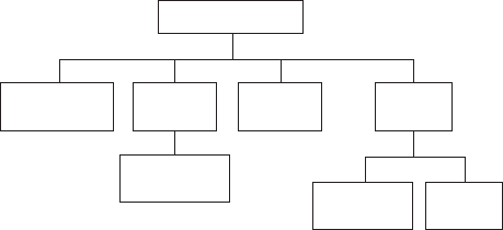
Figure 1.4 shows the probable position of the CAD
Director in the management structure. His department
will be providers of computer services to all other
computer users within the company.
however, demanded more specific and precise
specifications.
A national form of draughting presentation was
needed to promote a common understanding of the
objectives and in September 1927, BS 308 came to
fruition, as the recognized National Code of Practice
for Engineering Drawing.
The initial issue was A5-size and contained only 14
clauses. Dimensioning was covered in four paragraphs
and tolerancing in only one. The recommendations
were based on just two example drawings. The recom-
mended projection was first angle.
Revisions
The life span of BS 308 was 73 years and five revisions
were made. The first in December 1943, followed by
others in 1953, 1964, 1972 and 1985. The 1972 revision
was a major one, with the introduction of three separate
parts replacing the single document:
The fifth (1985) revision replaced the Imperial
standard with a Metric edition.
BS 308 was finally withdrawn and replaced by BS
8888 in 2000. The revisions were necessary to keep
abreast of technological innovations.
As manufactured products became more sophisticated
and complex, the progress and development of
manufacturing and verification techniques accelerated.
Advances in the electronics industry ensured more
applications in manufacturing with a very high degree
of sophistication. Much progress was also made since
that single paragraph in the original 1927 version
relating to tolerancing, together with the four paragraphs
and the two examples covering dimensioning. Geo-
metrical tolerancing was not referred to at all in early
versions. The subject gained prominence during the
1960s, especially when it was realized that a symbolic
characterization would assist in the understanding of
the subject by users and replace the use of lengthy
notes relating to geometric controls.
This activity was addressed by the major revision
in 1972 with the publication of Part 3, devoted entirely
to the dimensioning of geometric tolerancing.
The replacement of BS 308
Formerly, the Chief Designer and the drawing office
set, and were responsible for, company manufacturing
standards and procedures, for other disciples to follow.
This practice gradually eroded away because of the
advancement of progressive and sophisticated
techniques in the manufacturing and verification fields.
Increasing commercial pressure for Design for
Manufacture and Design for Inspection, created the
demand for equal status. During the period separate
standards were gradually developed for design,
manufacture and measurement. Each discipline utilized
Managing Director
Manufacturing
Manager
Chief
Engineer
Finance
Manager
CAD
Director
Chief
Draughtsman
Applications
Manager
Systems
Manager
Fig. 1.4
Why introduce BS 8888
and withdraw BS 308?
For 73 years, BS 308 was a highly regarded drawing
office practice document. Why the change and what
was behind the decision to withdraw BS 308 and replace
it with BS 8888?
A drawing standard
From time immemorial, drawings have been the medium
used to convey ideas and intentions. Hence the adage
that ‘a picture is worth a thousand words’. No need for
language, the picture tells it all. In recent years there
has, unfortunately, developed another opinion since
CAD appeared on the scene, that there is no need for
a draughtsman now as the computer does it all. The
truth of the matter is that the computer is able to extend
the range of work undertaken by the draughtsman and
is really a very willing slave. The evolution of the
Industrial Revolution required the ‘pictures’ to be more
detailed. In the pre-mass-production era, manufacture
was based on ‘matched fits’, with the assistance of
verbal communication. The advent of mass production
6 Manual of Engineering Drawing
similar terms but often with slightly different
interpretations despite their apparent commonality.
An urgent need to harmonize the meaning of these
terms was recognized by ISO. An international meeting
in 1989 formed a Joint Harmonization Group.
The Danish Standards Association funded a project
to bring all design, measurement, and metrology
standards together using definitions common to all,
but with appendices for each discipline.
A full ISO committee (ISO/TC 213) was formed,
with the Danish being responsible for the secretariat.
The task allocated to this very vibrant committee
progressed considerably, with many new international
standards being published.
A major happening that would affect the future of
BS 308 was the UK’s agreement in 1993 with the
European Standards Authority (CEN), whereby BSI
would withdraw standards relating to technical drawing
in favour of the implemented ISO standards covering
the same subject. Initially, BSI systematically withdrew
various clauses of BS 308 as the relevant ISO Standards
were introduced.
PD 308 was introduced in June 1996 as a guidance
document to assist the transition from BS 308 to the
implementation of ISO drawing standards. In 1999, as
was the case in 1927, major decisions were deemed
necessary, and the following were made:
• To transfer the United Kingdom totally to the ISO
Standards base.
• To prepare an applications standard to serve as both
a specification for specifying and graphically
representing products, and as a route map to the
ISO Standards.
• To withdraw BS 308.
From this positive commitment, BS 8888 was created
and published on 15 August 2000.
The complete comprehensive title of BS 8888 is:
BS 8888. Technical product documentation (TPD).
Specification for defining, specifying and graphically
representing products.
Basic differences
The fundamental differences between BS 308 and BS
8888 are:
• The title: Technical product documentation (TPD)
Specification for defining, specifying and graphically
representing products.
• Confirmation of the conventional use of the comma
as the decimal marker.
• BS 308 was a Code of Practice, a guidance document.
BS 8888 is essentially an applications specification,
providing a route map to 106 ISO standards. The
operative word is ‘specification’. BS 8888 carried
forward and contains a significant number of valuable
clauses contained in BS 308, which, at present, is
not in any ISO documentation.
• BS 8888 is capable of accommodating significant
technical changes, known to be in development, plus
the facility to accommodate future additions and
changes.
• With 106 related ISO standards, BS 8888 has a
much broader field of application than its predecessor
and its 30 related ISO standards.
• BS 8888 provides common understanding, and
acceptance between the designer and the metrologist
of ‘uncertainty’. These are caused by differences
between the Design Intent Measurand (Char-
acteristics Specification) and the Measured Value
(Characteristics Evaluation) of the actual
manufactured part.
• BS 8888 is a uniform source of reference and will
be regularly updated to keep abreast of developments
as new international standards are finalized and
implemented.
• It will capture any fundamental changes and will
reflect moves towards an integrated system for
definition, manufacture and verification.
• BS 8888 links each standard to the appropriate stage
of the design process and lays the foundations for
future development.
BS 8888 will be revised every two years.
Work undertaken by a drawing office will vary
considerably with different branches of industry.
Generally, work of a ‘design and make’ nature will
follow a plan which sets out stages in development
from the time a potential client makes an enquiry until
the completed product is delivered. The function of
the product will dictate many of the associated activities.
A vehicle manufacturer will not design and make
all of the parts used but subcontract components from
specialists. The engine incorporates electrical and
mechanical components and these need to conform to
agreed specifications. They must also be designed for
installation in specified areas and be suitable for
operation in well defined conditions. Component
manufacturers strive to improve quality and performance
in conjunction with end user.
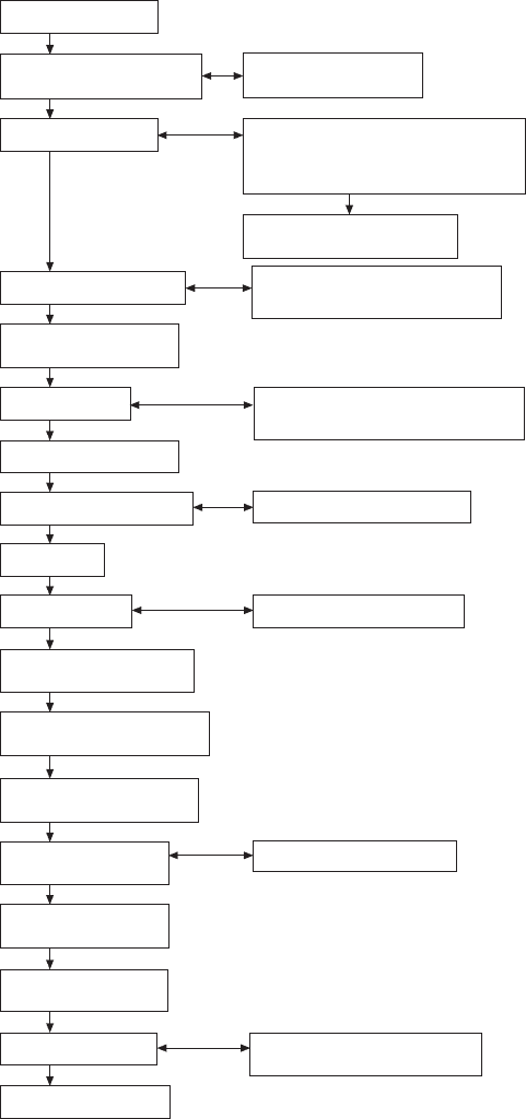
The stages in design and development for components
in this category are shown typically, step by step, in
Fig. 2.1.
1 A client requiring a certain product is often not
completely familiar with specific details and needs
the experience and advice from a specialist
producer to clarify initial ideas. When a range of
viable alternatives is presented, opinions can be
focused and firm decisions made.
2 The Chief Engineer in a company has the
responsibility of producing the company
specification for a product. He will no doubt seek
advice where aspects of the total design are outside
his range of experience, and where design is
involved on the fringes of Technology. However
a top executive plan needs to be carefully prepared
because at the outset the company must know
whether or not it wishes to entertain, or get involved
with, design proposals to satisfy the client. For
example, while rewards may well be great the
firm may not be able to cope with the scale of
financial and labour demands and delivery
requirements in view of current work. They simply
may not wish to take the risk and, in view of
available production capacity, the firm may prefer
not to tender for a possible order.
Chapter 2
Product development and
computer aided design
1 Clients requirements
2 Company specification
produced by chief engineer
3 Intial design concept
4 Agreed design concept
5 Preparation of working
drawings
6 Design review
7 Prototype manufacture
8 Confirmation and testing
9 Test results
10 Design review
11 Production drawing and
documentation
12 Make product and confirm
production specifications
13 Development program
for field trials
14 Final product
design input review
15 Design release for
manufacture
16 Production plant
and tooling
17 Production sample
18 Full scale production
2A Preparation of top
executive plan
3A Consultation with interfacing
specialists: design and production
engineers, quality controllers,
metallurgists, etc.
3B Allocation of specific
activity requirement
4A Provisional customer accep-
tance regarding installation:
space etc.
6A Manufacturing and costing
economics, future repeatability
guarantees
8A Verification and development
10A Audited technical analysis
14A Final design verifications
17A Verification of manufacturing
production processes
Fig. 2.1
8 Manual of Engineering Drawing
3 Drawings at this stage should be regarded only as
provisional. The exercise is needed as an aid to
thinking around the problem, with contributions
being made by specialists within the firm to ensure
feasibility.
CAD has many virtues at this stage of primary
design. All information, defined in mathematical
terms, can be stored in the system and manipulated
on the display. After the basic geometry is
established, design variations can be kept and in
redrawing alternatives, sections of the previous
proposals which were found to be acceptable can
be used repeatedly. At any point in development
the designer can take a printout, so that suggestions
and comments can be made by other technical
staff.
It is essential that the Company should
appreciate the extent of their commitment if a
firm order is accepted at a later date. This commit-
ment includes not only the technical ability to
complete the design and manufacture a satisfactory
product but also the financial issues relating to its
introduction on the factory production line.
4 With the completion of preliminary design work
an agreed design concept will have been esta-
blished, but it is necessary to obtain customer
approval before work continues. If our product is
to be used in conjunction with others in a large
assembly, then, for example, expected overall
dimensions and operational parameters need to
be confirmed with the client before money is spent
on further development.
5 If all is well, working drawings will be prepared.
These are not production drawings—at this stage,
we as a company have only ensured that our
proposals are in line with requirements and that
hopefully we shall be able to deliver. The object
now is to prepare working drawings to formulate
construction methods.
6 A design review is necessary to check the feasibility
of manufacturing, to ensure that all aspects of
design requirements have been incorporated in an
economic manner and to guarantee future supplies.
7 A prototype or a small batch may now be manu-
factured. The ultimate production methods of
manufacture will not be employed here. For
example, components which may be moulded could
be machined from solid to eliminate casting costs.
8 Prototypes are used for testing to make certain
that operational requirements of the specification
can be achieved. As a result design changes may
be necessary. Product tests cover all areas where
the component will be expected to function without
failure, and these could include use in extremes
of temperature and humidity, also when subject
to shock, vibration and fatigue.
9 Proven test results are vital to confirm the validity
of these tests.
10 A design review and analysis ensure that progress
at this point will be acceptable in every technical
aspect to each responsible member of the team.
11 Production drawing can commence now that the
performance targets from the prototype have been
confirmed. Drawings of the prototype will be
reviewed and modifications made to use full scale
production processes during manufacture. For plant
to be used efficiently plans need to be prepared
for loading and progressing work through the
factory. The necessary documentation now com-
mences.
12 Manufacture of the final product following pro-
duction of the prototype has involved modifications
and different manufacturing processes. It is
therefore prudent to check that the specifications
can still be kept.
13 Following trials where the equipment is used in
its operational environment and its performance
exhaustively checked, the design details can be
released for full scale production.
14 Production involves not only the use of machines,
but many jigs, fixtures, tools, gauges, inspection
procedures need to be planned, and auxiliary
equipment designed to move materials on and off
production lines.
15 Inevitably teething troubles occur and samples
are taken to verify that all plant and equipment
operates as planned. Economic production requires
that downtime is eliminated before full-scale
production commences.
Computer aided
draughting and design
CAD is much more than drawing lines by electronic
means. Similarly by the purchase of a CAD system, a
design does not emerge at the push of a button. ‘Buy
a computer and you don’t need a draughtsman’ is also
very different from reality. The engineering designer
is very much responsible for decisions taken at all
technical stages between conception and production.
The computer is an aid and performs as it is directed
with rapidity and accuracy. The following notes are
included to indicate areas of useful activity to assist
the draughtsman.
The preparation of two and three dimensional
drawings and the projection of associated views is the
‘bread and butter’ work in the drawing office. Service
manuals use exploded views so that people with no
technical training can follow assembly sequences.
Children stick together model kits with guidance using
pictorial diagrams.
CAD programs are available where a three di-
mensional model can be produced automatically given
two dimensional views. From the dimensions of the
component, the computer will calculate surface areas,
volumes, weights for different materials, centres of
gravity, moments of inertia and radii of gyration it can
also use the applicable values for stress and other
Product development and computer aided design 9
calculations, which are a necessary part of design.
Computer models permit a study of special relationships
and applications are given in the chapter which follows.
Models can be manipulated into pleasing forms for
artistic approval before production work follows.
Previous techniques included modelling with plasticine
and plaster, and applications ranged from ornaments
to boat hulls and car bodies. CAD has revolutionized
modelling capabilities.
Sales departments utilize 3D illustrations in brochures
and literature for promotional applications. Desk top
publishing from within the company can very simply
use illustrations generated as part of the manufacturing
process. The scanning of photographs into a CAD
system is also an asset especially as photographic work
can be retouched, manipulated and animated. Multi-
media applications with video and slide presentations
form a large part of selling and advertising.
Structural design requires a thorough knowledge of
engineering materials properties. Calculations of stress,
strain and deflection are essential to determine
proportions and dimensions in structural applications.
Computers now have the ability to perform millions of
calculations per second and with the availability of
powerful desk top models, finite element analysis has
developed as a principal method. One advantage of
finite element analysis is that design engineers can
produce better designs and eliminate dubious options
during the conceptual design phase. CAD systems
permit the rapid generation of models of proposed
designs as wire frames. The component can be defined
as a collection of small loaded elements. The computer
memory stores details of all the geometric data to define
each part of the frame. Numerical analysis will then
verify whether or not the suggested design will be
capable of supporting the expected loads. Formerly,
stress calculations were time consuming and in the
early days of computing, although the calculation time
was considerably shorter, computer time was relatively
expensive. This is now not the case and for this type of
design work CAD is an essential tool in the drawing
office.
CAD is very suitable for repetitive and fast
documentation where a product is one in a range of
sizes. Assume that we manufacture a range of motor
driven pumps operating at different pressures. Many
parts will be used in different combinations in the
range and the computer database documentation is
programmed accordingly. Company standard designs
will be offered when enquiries are received. A
computerized tender can be sent with the appropriate
specification and technical details. On receipt of an
order, all of the documentation relating to manufacture,
testing, despatch and invoicing will be available. An
obvious advantage is the speed of response to the
customer’s enquiry.
CAD will be linked to CAM (computer aided
manufacture) whenever possible. Documentation will
include parts lists, materials details of parts to be
manufactured or bought out, stock levels, computerized
instructions for numerical controlled machine tools,
instructions for automated assemblies, welding
equipment, etc. Printed circuit boards can be designed
on CAD and manufactured by CAM.
Production tooling requires the design of many jigs
and fixtures. A jig is a device which holds the component
or is held on to the component, locating the component
securely and accurately. Its function is to guide the
cutting tool into the component or for marking off or
positioning. A fixture is similar to a jig but it does not
guide the tool. Generally a fixture will be of heavier
construction and clamped to the machine tool table
where the operation will be performed. Jigs are used
frequently in drilling and boring operations. Fixtures
are a necessary part of tooling for milling, shaping,
grinding, planing and broaching operations. The use
of jigs and fixtures enables production to proceed with
accuracy, and hence interchangeability due to the
maintenance of tolerances (see Chapter 19) and
especially by the use of unskilled or semiskilled labour
and robotics.
The traditional method of jig and tool draughting
was to draw the component in red on the drawing
board. The jig or fixture would then be designed around
the component. This process ensures that the part is
located and clamped correctly, can be loaded and
unloaded freely, and that the machining operation can
be performed without hindrance.
With a CAD system, the component drawing can
be shown in colour on one of the ‘layers’ (see Chapter
3) and design work undertaken on the other layers.
Machining operations need to be checked to ensure
that tools and cutters do not foul any other equipment
in the vicinity. The path taken by the tool into its cutting
position should be the most direct and the shortest in
time. The actual cutting operation will take a different
time and the tool may traverse the component several
times, cutting away more material on each occasion.
Machining sequences can be simulated on the screen
and when the optimum method has been obtained, the
numerical program prepared. All relevant data for the
machining operation is converted into coded instructions
for continuous production.
Programs are available for the economic use of
metallic and non-metallic materials. Many engineering
components are manufactured by flame cutting intricate
shapes from plate or sheet and these need to be
positioned to minimize scrap. The cutting head is guided
by computer using the X and Y coordinates at each
point along the curve. Other applications use a variety
of cutters and saws to shape materials singly or heaped
into a pile, such as foams in upholstery or dress fabrics.
The tool draughtsman, for example, will use many
standardized components in tooling and designing
associated handling equipment for production. If a range
of parts is similar it is common practice to produce a
single drawing with dimensions in a table of the separate
features. A typical example is given in Fig. 7.2 and is
the normal manual draughting procedure. CAD can
however use a parametric technique where the