Smith G.T. Cutting Tool Technology: Industrial Handbook
Подождите немного. Документ загружается.


Conversely, for ‘Pilot’ hole drilling (Fig. 50b), these
mathematical formulae are modied in the following
manner:
F = C
F
d
bF
a
eF
s
uF
K
H
(kg)
M = C
M
d
bM
a
eM
s
uM
K
H
(kg mm)
Where:
a =
D
OC
(mm),
eF and eM =
exponents indicating the D
OC
’s inu-
ence.
ese axial force and torque formulae derived in the
work by Kaczmarek, are concerned with ‘so-called’ av-
erage twist drilling values. ese ‘averages’ are related
t
o drill diameters between 15 to 35 mm, having feed
ranges in the vicinity of 0.2 to 0.4 mm rev
–1
. erefore,
the entire axial force (F) and torque (M), comprises of
contributions of the lips, land and chisel point, in the
following manner:
•
Axial force (F) – lips (50%), land (10%) and chisel
point (40%),
•
Torque (M) – lips (80%), land (12%) and chisel
point (8%).
NB
ese contributing factors to axial force and
torque are for drill depths that do not exceed 2.5d.
If the drilling force is signicantly increased, then this
has the eect of distorting the drill sha. Such distor-
tion, causes the drill’s cutting edge to move forward
into the workpiece material, in this manner it jointly
increases the D
OC
and the drilling force. Correspond-
ingly, if the drilling force is reduced, the twist drill will
recover its shape, with the cutting edge moving back
from the workpiece, thus reducing both the D
OC
and
cutting force. is stretching and compression of the
drill’s sha – somewhat like a spring
14
– is unique to
twist drilling, being an unstable element in the cut-
ting process. By way of comparison, most cutting tool
14 ‘Lengthening eect’ is associated with the twist drill’s sha
being twisted by the application of torque, with elastically
springs-back upon release of the drilling torque. Not only
will the twist drill ‘spring’ , but it can also ‘bend’ due to the
increased thrust loads produced by high penetration rates.
edges are normally deected away from increases in
the load.
A common form of failure of twist drills in opera-
tion is from shattering, with such catastrophic failure
being related to the dynamic nature of twist drilling.
By way of illustration, a φ4
.5 mm long-series twist drill
is capable of withstanding a torque of approximately
6 N
m before it catastrophically fails. Normally, the
torque for most drilling operations is around 1 Nm.
Temperatures in Twist Drilling
e accumulation of heat in the vicinity of cutting is
an important factor in the cutting process, with much
of the mechanical energy necessary for machining be-
ing converted into heat, then conducted into the chip,
workpiece and tool (Fig. 51). e consequential ther-
mal phenomena are important, as they can aect the:
•
Mode of deformation – elastic/plastic behaviour of
the chip,
•
Machined surface – for metals the ultimate metal-
lurgical state of the material,
•
Tool wear rate – which depends upon a number
of criteria, such as the tool’s coating, cutting data
employed, work-hardening ability of the workpiece
and coolant delivery and its eciency.
It is imperative to comprehend the factors that control
both heat generation and its dissipation, together with
the tool and work’s temperature distribution in and
near the cutting zone.
A drilling operation can be considered as a complex
machining process, with specic and unique charac-
teristics, not least of which, are the production of chips
when drilling. ese chips are in continuous contact
with the drill utes and the generated hole’s surface.
Hence, any minute changes in the drill’s geometry, can
cause enormous modications to the either the drill’s
wear rate and its predicted life. Heat generated whilst
d
rilling will be transformed by a range of ‘states’ , in-
cluding:
•
Conduction – through the chips, workpiece and
drill,
•
Convection and radiation – via the ‘air-spaces’
in the hole as the drill penetrates deeper into the
workpiece.
e drilling temperature during a prolonged operation
can approximate steady-state conditions, with the heat
generated whilst cutting when employing a new drill
Drilling and Associated Technologies 101
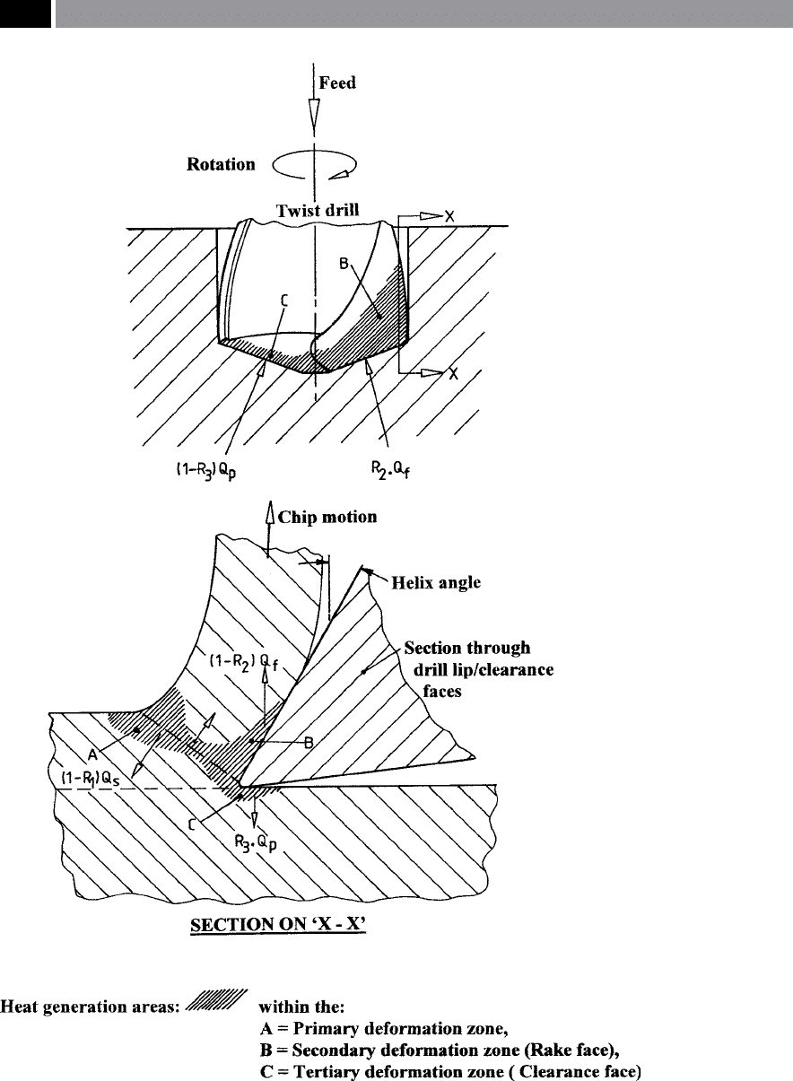
Figure 51. The drilling process and the asociated zones of heat generation whilst hole-making. [After:
Trigger and Chao, 1951]
.
102 Chapter 3

is associated with two distinct regions (i.e. see Fig. 51
– Section on X-X) at the:
•
Primary shear zone – where plas-
tic deformation occurs, this being the ma-
jor source of heat generation,
•
Secondary shear zone – from within the tool/chip
interface, where pronounced friction takes place.
NB
e drill clearance surface temperature, is sig-
nicantly aected by the rake face interface tem-
perature.
e bulk rise in the drill’s temperature is multifarious,
due to the necessity to consider a range of factors, in-
cluding: heat ow distribution, the geometric shape of
the conducting bodies, together with any variation of
thermal properties of both the drill and workpiece ma-
terials with temperature changes. e generated heat
distribution when drilling depends upon the thermal
properties of the tool, workpiece and chip. erefore,
the thermal diusivity (K/ρc), will determine the rate
at which heat transfers through the material, while
also controlling the penetration depth of the surface
temperature. While the absorption coecient (Kρc),
determines the quantity of heat being absorbed by a
given mass of material. Drilling temperatures vary
considerably in the research work undertaken over
the years, being heavily inuenced by a wide range of
cutting-related parameters, making it extremely di-
cult to obtain meaningful comparisons of local tem-
peratures in a real-time drilling operation. For exam-
ple, the scatter of ‘bulk’ temperature values for say, a
φ6mm twist drill, can vary between approximately 200
to 380°C, under steady-state drilling conditions
15
, for
comparable workpiece materials, making it very dif-
cult to obtain meaningful drill life comparisons.
Coolant delivery is imperative when drilling and to
this end, through-the-nose coolant operation enables
the lubrication and cooling of the drill’s point (Fig. 52c
– illustrating the coolant holes behind the lips). is
ecient technique of ensuring that the coolant gets to
the action of drilling, gives better chip control, helping
15 Twist drill interface temperatures have been reported to be
over 870°C in the workpiece’s ‘plasticity region’ , which some-
what contradicts the ‘bulk’ temperatures, although in mitiga-
tion, it should be said that these very high temperatures at the
interface at somewhat localised.
to reduce machining temperatures signicantly and
aid drill penetration rates, while increasing tool life.
Coolant holes through-the-nose are not restricted to
twist drills, as Spade-
16
and Gun-drills
17
, together with
Indexable drills also oen incorporate this coolant de-
livery feature, to remove heat and lubricate the cutting
edges.
3.1.4 Indexable Drills
Indexable drills have some signicant advantages over
their twist drilling counterparts (i.e. a range of both
indexable and twist drills are depicted in Fig.52a).
ese indexable drills – allowing the cutting inserts to
be changed (see Fig. 52c), permit faster cutting speeds
and enable a wider range of workpiece materials to be
successfully drilled than when utilising conventional
twist drills. Normally, indexable drills are limited to
s
horter hole depths of around ‘4D’ , than equivalent
diameter twist drills.
Indexable drills must be set up with care and in the
correct relationship to the machine tool’s headstock/
spindle, ensuring that both the drill’s and the spindle’s
centrelines are coincident, otherwise over-, or under-
sized holes may be produced (see Fig. 53a – top). Yet
another problem that needs to be addressed when
employing these indexable drills, is termed ‘radial
runout’
18
, which aects the inserts centre height and
should be limited to <0.127 mm. One advantage of be-
ing able to manipulate the indexable drill’s axis, is that
it can be used to adjust the drilled hole’s diameter, by
parallel adjustment of the drill’s and spindle’s respec-
tive centrelines – this being very useful for controlling
16 Spade drills are twist drills (i.e. bodies are normally manu-
factured from either 1018, or 1020 low-carbon steel) with a
standard blade being inserted at the drill’s point, enabling
holes to be generated up to 8D deep. Blades are usually coated
micrograin HSS with high-cobalt content, or coated cemented
carbides, ranging from stub drills to extra-long lengths, with
either straight, or spiral utes.
17 Gun-, or Deep-hole drills will be mentioned in some detail later
i
n this chapter, but they allow considerable length-to-diameter
ratios to be drilled in workpieces, necessitating high-pressure
coolant delivery, with ecient chip-ushing capabilities.
18 Radial runout refers to misalignment in the radial direction,
which should be minimised, as it alters the position of the
drill’s cutting inserts.
Drilling and Associated Technologies 103
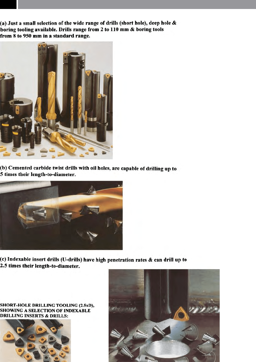
Figure 52. Short hole drilling. [Courtesy of Sandvik Coromant].
104 Chapter 3

drilled hole tolerances. On turning centres this can be
readily achieved by modifying the CNC cutting pro-
gram, to oset the drill with respect to the machine’s
centreline. Moreover, for turning operations employ-
ing drilled features, then the indexable insert’s top sur-
faces must remain parallel to the X-axis of the machine
tool. e arrangement of the inner and outer cutting
edges of an indexable insert drill relative to each other,
together with the drill’s position to the axis of rotation
are vital for perfect drilling operations
19
(i.e. see Fig.
53a). e cutting inserts positions by possible X-axis
adjustments, are critical for the: smooth running, re-
sultant cutting forces and, will inuence the drilled
hole’s alignment. Preferably, the cutting edges are ar-
ranged in such a manner that the inner- (SBI) and
outer-inserts (SBA) have identical cutting widths (Fig.
53a – bottom le). When new insert cutting edges are
utilised, this results in a balance of the cutting forces in
the Y-axis, guaranteeing drilled holes of accurate size
and surface texture without ‘
retraction striae’
20
. When
selecting the appropriate adjustment angles (χ
i
) and
(χ
A
), the lines of force via feed forces (F
a
and F
i
) will co-
incide with the drill’s axis in the centre of the clamping
sha (Fig. 53a – top). Hence, the clamping sha must
only transmit torque resulting from the cutting forces
and the bending moment of the resultant cutting force
which will be present. Typically, the outer insert’s re-
sultant cutting force F
A
(i.e. Fig. 53b) is comprised of
the following forces:
•
Remaining cutting force (∆F
c
) – generated through
greater wear rates at the periphery of the outer cut-
ting insert,
•
Passive force (F
p
) – generated by the corner radius
of the outer cutting insert.
With indexable drills, the chip ute is selected so that
the drill’s prole from the tip up to the chip ute, has
its runout twisted by between 65° to 85°. In the vicin-
ity of the chip ute the runout (i.e. the longest ‘lever
arm’ of the force), is where the maximum resistance
19 Some tooling manufacturers recommend that an indexable
drill’s inner insert is positioned slightly below the spindle’s cen-
treline, as this allows a small core of uncut material to pass
over the top surface of the insert and break o – being carried
away with the rest of the chips.
20
‘Retraction striae’ refers to the ‘trail-lines’ resulting from the
outer insert’s gouging, or ploughing the previously drilled sur-
face as it is withdrawn from the hole.
moment to the resultant cutting force F
A
is found.
e bending strength attained in this manner can be
greatly increased by employing round proled chip
utes. is rounded chip ute cross-section, does not
signicantly weaken the drill’s body and provides op-
timum chip-ow – even when drilling long-chipping
workpieces. A taper of the tool holder behind the in-
sert seats, prevents a ‘squeezing’ of the chips between
the drill and the drill-hole wall.
Due to the design of the indexable drill, the two
cutting inserts are subjected to very dissimilar stresses
when drilling. For example, the indexable drill (Fig.
53a – bottom), has the outer insert being subjected
to greater stress than its inner counterpart, typically
having both thermal and abrasive stresses, while the
inner insert must have high toughness characteris-
tics. Some cutting tool manufacturers recommend so-
called ‘
mixed-tipping’
21
of inserts, where a toughened
grade is used for the inner insert and a wear-resistant
grade for the outer insert. However, some discretion
should be used when utilising indexable drills with
mixed cutting inserts, so perhaps reference back to
the tooling manufacturer may be advisable if produc-
tion quantities are sucient in order to optimise this
potential ‘mixed grade strategy’. Typically, by exploit-
i
ng ‘mixed-tipping’ , for example when machining
free-cutting steel grades cutting speeds of up to 400 m
min
–1
are possible, whereas when drilling low-silicon
aluminium grades cutting speeds of 600 m min
–1
can
be achieved with tool lives of up to 45 min of cutting
time per edge.
Several design factors will inuence an indexable
drill’s performance, these include:
•
Sintered cutting insert chip-breakers – these will
improve chip control and enable high penetration
rates to be utilised,
•
Advanced ute design – allowing deeper chip gul-
lets, thus minimising chip-jamming tendencies,
•
Faster-, slower-, or straight-uted designs – with
wider ute proles reduce chip-binding and degra-
dation of the drilled hole surface, whilst also im-
proving penetration rates,
•
Cutting insert shape – utilising square (i.e. having
4 cutting edges), rectangular (i.e. with two edges),
or triangular inserts (i.e. having three edges) – the
21 ‘Mixed-tipping’ , refers to having dissimilar grades of inserts
for the outer and inner cutting edges, as they full dierent
mechanical working criteria whilst drilling.
Drilling and Associated Technologies 105
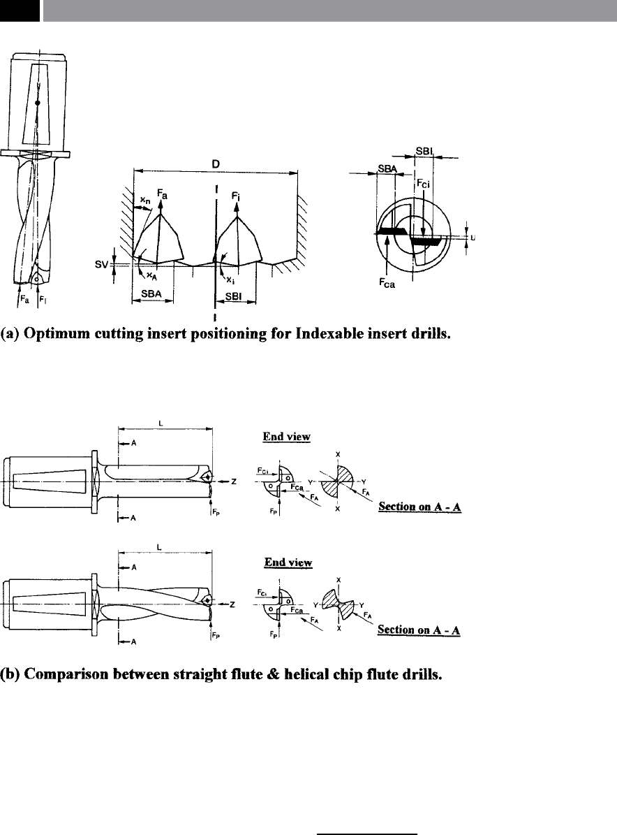
Figure 53. Indexable insert drills – insert position and ute geometry. [Courtesy of Kennametal Hertel].
latter being the most popular version for general-
purpose drilling operations.
NB D
ouble-sided cutting inserts are available, but
are mainly used for milling operations.
One major advantage that indexable drills have over
twist drills, is that they can be oset to produce dier-
ent hole diameters. is oset for turning centres can
b
e up to 3.8 mm, or 7.6 mm on a diameter
22
, which
in reality, amounts to a ‘ne-boring’ operation, giv-
22 On machining centres this oset is somewhat less, with the max-
imum radial oset being approximately 1 mm, or 2 mm on dia-
meter. Of note, is that when an indexable drill is oset, then the
maximum feedrate should be no greater than 0.15 mm rev
–1
.
106 Chapter 3

ing considerable scope in diametric sizing of holes.
ese drills should be selected for the minimum
overhang and need to have both the drill’s and ma-
chine tool’s centrelines p
arallel
23
to within 0.076 mm,
or better.
By utilising an indexable drill on a turning opera-
tion, they can be benecial when attempting to start
drilling angled, or uneven workpiece surfaces, as illus-
trated by some of the surface faces depicted in Fig. 54.
Indexable drills, employed for such non-at workpiece
faces, obviates the need for either a previous counter
boring, or spotfacing operation.
e major advantage of indexable drills over either
their HSS, or carbide twist drill counterparts, is their
ability to run at much higher rates. For example and,
by way of simplistic comparison, if a φ1
8 mm hole has
to be drilled in free-cutting stainless steel, then an:
•
HSS twist drill – can be run at 16.8 m min
–1
with
a 0.2 mm rev
–1
feed would produce 280 rpm at
57 mm min
–1
,
•
Solid carbide twist drill – can be run at 61 m min
–1
with a 0.1 mm rev
–1
feed would produce 1,019 rpm
at 103 mm min
–1
,
•
Indexable drill – can be run at 170 m min
–1
with
a 0.76 mm rev
–1
feed would produce 2,852 rpm at
217 mm min
–1
.
NB e indexable drill can b
e run up to 0.8 mm rev
–1
and if one were to attempt to utilise a twist drill with
the cutting data shown above, then it would either
burn-out, or catastrophically fail in the endeavour.
An important safety note when using these indexable
drills in turning operations, is that the high penetra-
tion rates, coupled to the exit of a through hole in the
part, creates a slug which is thrown clear from either
the chuck, or from the rear of the bore of the machine’s
headstock at tremendous force. If the machine tool is
not guarded appropriately, it could prove to be hazard-
ous to any operator in the local vicinity.
23 Axis oset/misalignment: for example, if there is a 1° mis-
alignment between these centrelines, then the centrelines will
be 0.43 mm apart at 25 mm from the point at which the cen-
trelines cross at the tool’s tip.
3.1.5 Counter-Boring/Trepanning
A counter-boring operation is an oen utilised tech-
nique for the enlargement of previously manufac-
tured holes, normally to provide them with accurate
dimensions and/or improved surface nish (i.e. see
Fig. 55a). Counter-bores are also produced to register
a larger-faced shouldered sha, or to sink a precision
cap-head bolt below the clamped part’s surface. In this
latter case, oen the previously-drilled hole is used
to align the bolt’s axis, by using a counter-boring tool
with a ‘pilot-bush’ of the same drilled diameter to act as
a guide to allow machining to a correct counter-bored
depth.
Counter-boring heads are employed to open-out
existing holes (Fig. 55a). e heads were in the past,
oen of a single insert design, but latterly, they are
produced with multiple inserts – particularly when the
working clearance is such, that it cannot cope with by
the single insert variety. e multi-insert counter-bor-
ing heads, can have their inserts nely diametrically-
adjusted by means of precision wedge and radial ad-
justing screws.
A trepanning operation is undertaken in one op-
eration, but instead of machining the complete hole,
only part of the hole is cut, leaving a core (Fig. 55b).
For large workpiece dimension machining, a trepan-
ning operation uses less power and axial pressure than
other equivalent manufacturing processes. However,
one major problem occurs with the trepanning opera-
tion, which is that the core produced as the trepanning
tool penetrates into the workpiece, becomes quite dif-
cult to handle (i.e. see Fig. 55b -lower diagram).
Trepanning heads are normally utilised on:
•
Large workpiece diameters – greater than 120 mm,
•
Limited machine tool power – alternatively, if it is
not prudent to switch to another machine tool and/
or lose part orientation and register
24
,
•
Core utilisation – large cores can be usefully
utilised as precision material stock.
24 Part orientation and register, refers to the initial setup, where
once the workpiece has been clamped and partially machined,
it cannot be satisfactorily removed then reset without a loss of
both accuracy and precision.
Drilling and Associated Technologies 107
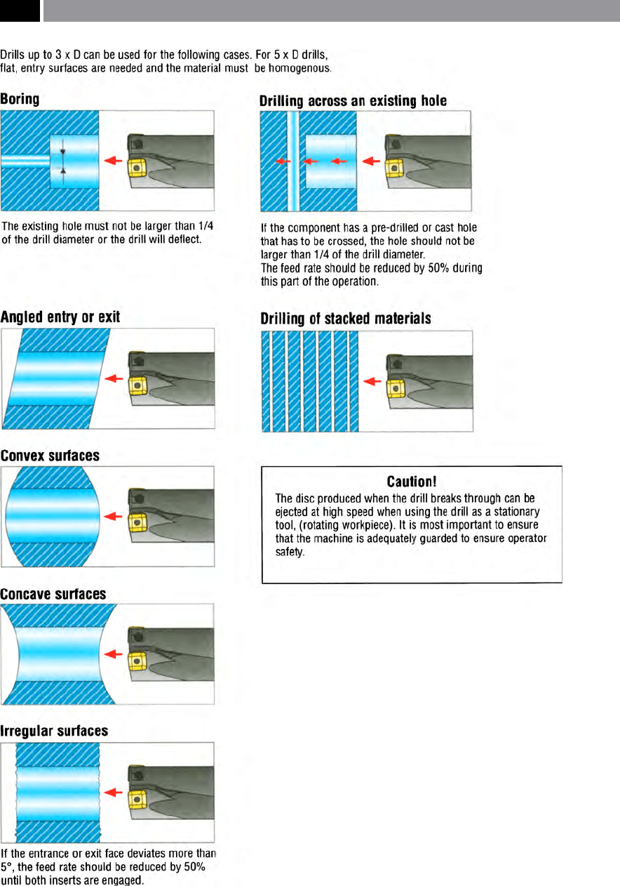
Figure 54. A wide range of drilling/boring operations can be undertaken using indexable insert drills. [Courtesy of Seco Tools].
108 Chapter 3
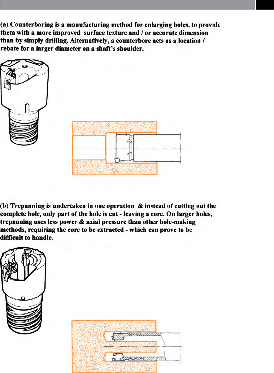
Figure 55. Counterboring and trepanning. [Courtesy of Sandvik Coromant].
Drilling and Associated Technologies 109

3.1.6 Special-Purpose, or Customised
Drilling and Multi-Spindle
Drilling
Most of today’s Special-purpose, or Customised Drills
and Multi-spindle drills are normally designed and
manufactured to meet the following criteria:
•
Long production runs
25
– these enable the extra
cost of this purpose-designed and built tooling to
amortised
26
over the cost of the production period,
•
Short cycle times
27
– when time is the ‘essence of
importance’ in the production of the component,
but it is not necessarily related to the overall quan-
tity of the production run,
•
Tooling accuracy is reected in the part’s manufac-
ture – if for example the precision part must have
all its component features in accurate alignment,
or in a specic relationship to a particular datum
28
:
face, plane or point.
Special-purpose, or Customised tooling is normally
required if one, or several of the criteria mentioned
above are to be met. To have a tooling manufacturer
design special-purpose tooling to meet the production
demands of manufacture, is not undertaken lightly, as
for complex tooling, its: design, build and prove-out,
prior to use, could prove to be expensive. However,
many companies resort to this type of custom-built
tooling, because it is the only way that the product can
be manufactured economically. Oen, multiple fea-
tures are incorporated into just one tool, typically for
hole- and post-hole making operations, such as those
depicted in Fig. 56a. A relatively simple example of
this special-purpose tooling is illustrated in Fig. 56b,
where three production operations for the manufac-
ture of the female part of the pull-stud mechanism for
a milling cutter toolholder is depicted, namely, drilling,
25 Long production runs usually refers to some form of continu-
ous production , or large batch sizes, of > 5,000 components,
to make the cost of the Special-purpose tooling viable.
26 Amortisation, refers to the ‘pay-back’ of the tooling over the
‘life’ of the production of the parts produced.
27 Short cycle times, are considered to be the quickest time that the
part can be produced, under ‘standard’ machining conditions.
28 Datum – the term refers to origin of the measurements for
the particular component feature, which could be from a face,
plane, or point.
chamfering and counter-boring. In this case, not only
does the usage of special-purpose tooling here seem
the obvious solution, as it combines these individual
operations in one, it has the advantage of meeting all
three of the production criteria listed above, with the
added advantages of both using fewer tools and utilis-
ing less space in the tool magazine. Some special-pur-
pose tools are very complex in their design and quite
sophisticated in operation, but their supplementary
cost more than outweighs this by the production gains
oered by their consequent implementation.
M
ulti-spindle drilling
29
tooling is ideal when a series
of hole patterns are required on a component, such as
for specic congurations of: pitch circle diameters,
hole grid patterns, line of holes, or a combination of
these (i.e. see examples of specic patterns in Fig. 57
– top right). Hole pitch circle diameters can easily be
accommodated, for large and small pitch diameters on
the same tooling, Likewise, hole line and grid patterns
can be quite diverse, within the diametral area of the
‘cluster plate’ (i.e. see Fig. 57 – top le).
Multi-spindle drilling heads utilise a main drive
gear which is engaged with an idler and then onto the
drill spindle gear, this being attached to the individual
drill (i.e. see Fig. 57 – exploded view of a typical sys-
tem). e cluster plate orientates the individual drill
spindles and their rotational speeds can be margin-
ally increased, or decreased, by changing the driver-
to-driven gear ratio, moreover, their rotational direc-
tion can be changed by the introduction of another
idler into the gear train. erefore, if additional idlers
are present, to change the drill’s rotation, then the an
appropriate le-hand drill would be required here.
By purposefully modifying each drill’s rotational di-
rection, this has the advantage of minimising overall
torque eects on the multi-spindle drilling head, al-
lowing a large number of drills to be utilised for one
particular operation (i.e. see Fig. 57 – lower le-hand
photograph). An important point in utilising multi-
spindle drilling heads, is presetting their respective
drill lengths, so that they engage with the workpiece’s
surface at the correct height.
By the correct production application of both Spe-
cial-purpose and Multi-spindle drilling tooling, then
29 Multi-spindle tools, refer to more than one individual tool ro-
tating in its respective toolholder, enabling several holes to be
manufactured in just one operation.
110 Chapter 3