Stacey F.D., Davis P.M. Physics of the Earth
Подождите немного. Документ загружается.


//FS2/CUP/3-PAGINATION/SDE/2-PROOFS/3B2/9780521873628C11.3D
–
157
– [149–162] 13.3.2008 11:19AM
The Anderson criteria are derived from two
basic principles: (i) there are no stresses, normal
or shear, across a free horizontal surface, and (ii)
the largest shear stress occurs across planes
between the directions of maximum and mini-
mum principal stress. The existence of the free
surface requires that one of the principal stress
directions be vertical, normal to the surface. This
applies not just to the surface itself but to all
depths much smaller than the horizontal scale
over which the stresses are averaged, and it is
therefore a constraint on theories of the causes
of geologically observed surface faults. Thus, the
other two principal stresses are horizontal and
there are only three ways in which they can be
oriented. The vertical stress may be the direction
of maximum,
1
, intermediate,
2
, or minimum
principal stress,
3
, and in each case the other
two principal stresses are the horizontal stresses.
As generally applied, the principal stresses are
converted to the rock mechanics convention
with compression positive. With this convention,
the ranking
1
>
2
>
3
corresponds to the most
compressive to least compressive stress.
In a region of compression,
1
and
2
are both
horizontal, with
3
vertical, and thrust (reverse)
faulting (Fig 11.7) occurs. Extension, in which
both horizontal stresses are smaller than the
vertical (and are negative at the surface), causes
normal faulting (Fig. 11.7). Strike-slip faulting
(Fig. 11.7) occurs when the maximum and mini-
mum stresses are horizontal.
An unconfined rock will fail when subjected
to shear stress greater than its internal strength,
S
0
. The failure usually takes the form of relative
motion across a plane that is oriented in the
direction of maximum shear, i.e. at 458 to the
maximum and minimum principal stresses. At
depth, rocks are more resistant to shear failure
because they are subjected to confining pressure
of the overburden. In addition to overcoming
intrinsic internal strength, shears must be large
enough to overcome frictional effects from the
overburden pressure. The frictional stress is
equal to the product of normal stress,
n
, across
a fault plane (with compression taken as posi-
tive) and a friction coefficient. The failure plane
is then not the 45
o
plane of maximum shear,
because the frictional stress is reduced by
turning the normal to the failure plane towards
the axis of minimum stress. This occurs at an
angle such that the reduction in shear stress is
compensated by a reduction in the normal stress.
Coulomb’s equation describes this process and
gives the condition for failure as
¼
f
n
þ S
0
; (11:36)
where t is the limiting shear stress at which fail-
ure occurs,
f
is the friction coefficient, and S
0
is
the internal strength or cohesion. The straight
line in Fig. 11.6(a) gives the failure criterion
(Eq. (11.36)), which lies tangent to the limiting
Mohr circle at the point of failure. The rock is
stable for stress fields having circles that lie
below the failure line. As Fig. 11.6(c) illustrates,
increasing pressure stabilizes against failure
because larger shears are required to generate
Mohr circles that intersect the failure criterion.
From laboratory observations, Byerlee (1978)
found that a value
f
¼0.6 to 0.85 applies to many
common rock types. The lower value applies to
wet rock or rock under high confining pressure
and the upper value to dry rock at low confining
pressure. Equation (11.36), known as Byerlee’s
law, is the equation of a straight line (a better
approximation is a convex curve) that is plotted
on the Mohr diagram to describe conditions for
failure. At the point of failure, 2 of Eq. (11.30) is
an obtuse angle. Therefore, the angle, ,between
the normal to the plane of failure and maximum
principal stress direction is greater than 458.The
slope of the failure line is tan ,where is
referred to as the angle of internal friction, so that
f
¼ tan : (11:37)
Then from Fig. 11.6(a),
2 ¼
p
2
þ : (11:38)
In structural geology one is interested in , the
angle between the dip of the fault plane and
1
,
which is the complement of . Then
¼
p
2
¼
1
2
tan
1
ð1=
f
Þ: (11:39)
For
f
¼0.85, ¼24.88. In general, failure planes
are predicted to occur at small angles to the
directions of maximum principal stress.
11.5 CRUSTAL STRESS AND FAULTING 157

//FS2/CUP/3-PAGINATION/SDE/2-PROOFS/3B2/9780521873628C11.3D
–
158
– [149–162] 13.3.2008 11:19AM
The Coulomb criterion applies to dry materi-
als. For rock subjected to internal pore pressures,
the outward pressure of the fluid reduces the
effective normal stress on the solid matrix, and
the rock fails at lower shear stress. The Mohr
circles in Fig. 11.6(c) move to the left, corres-
ponding to a reduction in normal stress. We
replace normal stress in Eq. (11.36) with an effec-
tive normal stress
n
given by the externally
applied normal stress,
n
, minus the internal
stresses that are generated by pressurized fluids
in the rock. The internal pore fluid pressure gen-
erates an outward directed stress, P
F
, propor-
tional to the pressure in the fluid and the area
fraction of the fault plane occupied by pore
space. In many sedimentary rocks, pore fluids
are pervasive in wet grain–grain boundaries
and P
F
is nearly equal to the pore pressure. In
more compact rock, with restricted fluid filled
pores, P
F
is generally smaller, although, in some
cases, sealed pores may have high internal pres-
sures. Equation 11.36 becomes
¼
f
ð
n
P
F
ÞþS
0
; (11:40)
written as
¼
f
n
ð1 l
H
ÞþS
0
(11:41)
or
¼
f
n
þ S
0
;
where l
H
, known as the Hubbert–Rubey coeffi-
cient, is the ratio of pressure from pore fluids to
normal stress, and
is the effective normal
stress. Then
l
H
¼
P
F
n
: (11:42)
Alternatively,
¼
f
n
þ S
0
; (11:43)
where
f
¼
f
ð1 l
H
Þ is the effective friction
(Section 13.7).
We return to the Anderson criteria, which
describe maximum stress directions for the differ-
ent fault mechanisms. In a compressional regime
where the maximum principal stress is horizon-
tal, the dips of fault planes, relative to the surface,
are expected to be shallow. In a normal faulting
regime where the maximum stress is vertical, the
dips of fault planes are expected to be steep. In a
strike-slip regime faults should be vertical and
angled closer to the direction of maximum prin-
cipal stress than to the direction of minimum
principal stress. However, geological and seismo-
logical observations of faults indicate that their
orientations can be explained by these equations
with a value of
f
much smaller than suggested by
laboratory measurements (0.6 to 0.85), as in
Table 11.2. These criteria refer to mechanically
isotropic material, but in many cases established
faults are planes of weakness that control fault
movements. Then the Anderson criteria refer to
the direction of stresses that caused the faults in
the first place and not necessarily to the present
stress.
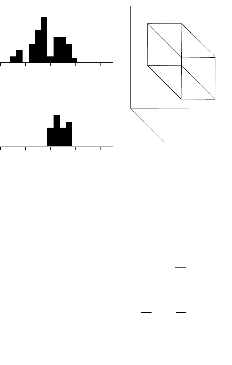
Sibson and Xie (1998) plotted a histogram of
the dip angles of 31 reverse faults for which
there are seismic or field estimates of the geom-
etry of the fault planes (Fig. 11.8(a)). The mean of
their broad distribution is 398. Jackson and
White (1989) present a histogram of dips for 15
normal fault events with a mean value of 50.38
(Fig. 11.8(b)). The modest number of events in
each case invites doubt about the statistical sig-
nificance of the small average deflections from
458, but they are clearly incompatible with fric-
tion coefficients as high as the laboratory values
of 0.6 to 0.85. While we know that established
fault planes have powdered, soft material (gouge),
compatible with a low friction coefficient, this
Table 11.2 Average fault dips for different
friction coefficients compared with
observations by Sibson and Xie (1998) and
Jackson and White (1989)
Dip
(
f
¼0.85)
Dip
(
f
¼0.2) Observations
Normal
fault
65.28 50.7 8 50.38
Strike-
slip
fault
vertical,
24.88
to
1
vertical,
39.38 to
1
–
Reverse
fault
24.88 39.3 8 398
158 DEFORMATION OF THE CRUST: ROCK MECHANICS
//FS2/CUP/3-PAGINATION/SDE/2-PROOFS/3B2/9780521873628C11.3D
–
159
– [149–162] 13.3.2008 11:19AM
does not explain how the faults formed in the
first place and that is what matters in consider-
ation of the angles. Evidently pore pressure in
faults has a more significant effect that is yet
to be satisfactorily explained. It is especially
obvious that the conventional concept of friction
can apply to only very shallow faults and needs
modification to apply to earthquakes at even
modest depths, where overburden pressure
ensures very high normal stresses across faults.
11.6 Crustal stress: measurement
and analysis
A basic starting point in generating a theoretical
model of stresses is to find solutions that satisfy
the equations of motion. The equations of
motion in a continuous medium are found by
applying Newton’s third law to elementary vol-
umes subjected to a stress field
ij
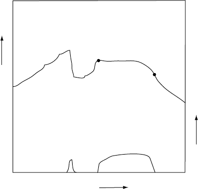
. Consider a
parallelepiped of length x and cross-sectional
area y z (Fig. 11.9). The normal force acting on
the face ABCD is
F
1
¼
xx
yz; (11:44)
and on face A
0
B
0
C
0
D
0
,
F
2
¼
xx
þ
@
xx
@x
x
yz: (11:45)
The net force from this stress component is:
F ¼ F
2
F
1
¼
@
xx
@x
xyz: (11:46)
If we consider the shear stresses on the other two
sides in a similar fashion we obtain additional
forces in the x-direction of
@
yx
@y
xyz;
@
zx
@z
xyz:
Summing these forces, the net force per unit
volume in the x-direction due to the stress
imposed on the parallelepiped by the material
exterior to it is
force
volume
¼
@
xx
@x
þ
@
xy
@y
þ
@
xz
@z
: (11:47)
0 1020304050607080
1
2
3
4
5
6
7
8
90
Reverse Faults
Dip Angle (degrees)
Number
31 events
0 102030405060708090
Dip Angle (degrees)
1
2
3
4
5
6
7
8
Normal Faults
Number
with surface faulting
15 events
FIGURE 11.8 Histograms of measured dip angles of
faults, as tests of the Anderson criteria (Table 11.2).
(a) Reverse faults (mean dip angle 398), after Sibson
and Xie (1998). (b) Normal faults (mean dip angle 50.38),
after Jackson and White (1989).
x
y
z
DC
BA
A' B'
C'
D'
o
FIGURE 11.9 Geometry of an elementary volume in a
stressed medium.
11.6 CRUSTAL STRESS: MEASUREMENT AND ANALYSIS 159

//FS2/CUP/3-PAGINATION/SDE/2-PROOFS/3B2/9780521873628C11.3D
–
160
– [149–162] 13.3.2008 11:19AM
In addition to these external forces, the vol-
ume may be subjected to an internal body force,
most importantly gravity, mg, which must
be added to the above equation. Let X be the
component of the body force per unit mass
(g in the gravity case). Then the force per unit
volume is X. The equation of motion becomes
force=volume ¼ density acceleration. For three
dimensions
@
xx
@x
þ
@
yx
@y
þ
@
zx
@z
þ X ¼
¨
u
x
;
@
xy
@x
þ
@
yy
@y
þ
@
zy
@z
þ Y ¼
¨
u
y
;
@
xz
@x
þ
@
yz
@y
þ
@
zz
@z
þ Z ¼
¨
u
z
: (11:48)
Solutions to these differential equations are
used in numerous applications from seismo-
logy to structural geology. In this section we
consider the equilibrium versions with no
acceleration.
The equations of motion (11.48) may also be
expressed in cylindrical or spherical coordinates
(Jaeger and Cook, 1984). The equilibrium equa-
tions for horizontal plane stress in cylindrical
coordinates are
@
rr
@r
þ
1
r
@
r
@
þ
rr
r
¼ 0;
@
r
@r
þ
1
r
@
@
þ
2
r
r
¼ 0;
(11:49)
where the body forces are omitted because we
are considering (r,) geometry in the horizontal
plane perpendicular to the gravitational force.
Consider a cylindrical hole of radius R in an
elastic medium subjected to a pressure P. The
solution that satisfies Eq. (11.49) is
rr
¼P
R
2
r
2
;
¼P
R
2
r
2
;
r
¼0; for r
4
R:
(11:50)
This solution describes stresses around pressur-
ized conduits such as a magma conduit or a pres-
surized borehole.
A related solution, and one of the most impor-
tant in rock mechanics, gives the stresses outside
a pressurized cylindrical hole with specified
principal stresses {
1
,
3
} at infinity (Jaeger and
Cook, 1984). It is the theoretical basis for
interpreting stress measurements in the Earth
using hydrofracture, overcoring and borehole
breakouts.
rr
¼P
R
2
r
2
þ
1
2
ð
1
þ
3
Þ 1
R
2
r
2
þ
1
2
ð
1
3
Þ 1
4R
2
r
2
þ
3R
4
r
4
cosð2Þ;
¼P
R
2
r
2
þ
1
2
ð
1
þ
3
Þ 1 þ
R
2
r
2
1
2
ð
1
3
Þ 1 þ
3R
4
r
4
cosð2Þ;
r
¼
1
2
ð
1
3
Þ 1 þ
2R
2
r
2
3R
4
r
4
sinð2Þ;
(11:51)
where is measured from the direction of
1
.
Hydrofracture is the process whereby water
pressure in a conduit, such as a borehole,
becomes large enough to fracture the surround-
ing rock, forming a crack into which the water
flows. Hydrofracture occurs in natural systems
such as in geothermal regions. The equivalent
process, magma-fracture, occurs in volcanic
areas where magma fractures rock to generate
dikes and sills. Hydrofracture is used in the oil
industry to fracture oil reservoirs, and to
increase permeability for secondary recovery of
reserves. The hydrofracture process involves
sealing off a segment of the borehole with pack-
ers, and pumping liquid into the sealed section
until the surrounding rock breaks. The pressure
is monitored throughout, and various methods
are used to estimate the directions and orienta-
tions of fractures. In addition to its oil reservoir
use, the method is one of the most important in
determining the regional stress field, because
fractures open in the direction of minimum prin-
cipal stress, and fluid flow into the cracks is
governed by their dimensions.
In order to initiate a vertical fracture, for
example, the tangential stress,
, at the bore-
hole, r ¼R in Eq. (11.51), must be equal to the
tensional strength of the rock, T
0
,
¼T
0
:
160 DEFORMATION OF THE CRUST: ROCK MECHANICS
//FS2/CUP/3-PAGINATION/SDE/2-PROOFS/3B2/9780521873628C11.3D
–
161
– [149–162] 13.3.2008 11:19AM
From Eq. (11.51) we obtain at r ¼R,
¼P þð
1
þ
3
Þ2ð
1
3
Þcosð2Þ:
The tangential stress becomes most tensile (nega-
tive) at ¼0. Then
T
0
¼ P þ
1
3
3
; (11:52)
i.e. a crack forms at P
1
¼T
0
þ3
3
1
(Fig. 11.10)
and water flows from the borehole into the
crack. Before the crack becomes very large and
influences the regional stresses by its presence,
the pressure is reduced, flow ceases, and then
the pressure is applied once more. This time the
internal pressure inflates an already broken
crack of no tensile strength and we obtain the
simpler equation
P
b
¼ 3
3
1
: (11:53)
P
b
is the breakdown pressure, which is measured
at the well-head. Flow resumes at P ¼P
b
(Fig 11.10).
We thus have one equation, Eq. (11.53), in two
unknowns,
1
and
3
,andrequireafurther
measurement. The crack is allowed to grow. If
the material is impermeable and isotropic, the
usualassumption,thecrackwillopennormalto
3
andextendinthedirectionof
1
.Afterthe
crack has been fully inflated, the pressure at the
well-head is reduced, and the crack collapses,
reducing the flow to zero. For a large crack
1
has no influence on the flow, and the internal
pressure is dependent on P
3
.Thecrackcloses
when P
3
¼0. Thus the shutin or closure pres-
sure, P
c
, measured just before closure, gives an
estimate of
3
. In many situations the third prin-
cipal stress can be taken as
2
¼gz. Then the
hydrofracture measurement can, in principle,
determine all the components of the stress field.
The direction the crack travels is measured by
in-borehole methods involving televiewers, imp-
ression packers, or externally by detecting the
deformation field at the surface by arrays of very
sensitive tiltmeters (Davis, 1983).
Another method of estimating stresses,
known as overcoring, involves drilling out the
rock in a cylindrical annulus around a borehole,
effectively isolating it from the tractions of the
surroundings. Calipers are used to measure the
change in shape as a function of depth after
overcoring. The associated strains may be con-
verted to stresses if the elastic constants have
been determined so that Eq. (11.51) can be
applied to determine
1
and
3
.
Also, Eq. (11.51) is applied to the analysis of
borehole breakouts. These are localized failure of
the borehole walls in which rock spalls off along
sections of the circumference closest to the axis of
minimum principal stress
3
.Asqueezedhole
breaks along its sides. Equation (11.51) with
P ¼0 describes the stress concentration that
occurs when a hole is drilled into a region of
principal stresses
1
, v
1
, v
3
,
3
. The greatest com-
pression in the rock occurs for ¼908,which
for r ¼R gives
¼3
1
3
. The compressive
stress causes cracks that are parallel to the cir-
cumference and flakes of rock spall from each
side leaving the bore elongated in the horizontal
plane. The direction of minimum principal stress
is mapped by inserting a caliper and measuring
the orientation of the elongation. While useful in
giving stress directions, this method gives no
information on the magnitudes of the stresses.
Time
Pressure
Flow
Pressure
Flow
Hydrofracture
P
1
P
b
P
c
FIGURE 11.10 Pressure at the well-head for a
hydrofracture experiment. Pressure in the borehole is
increased to P
1
until the rock fractures, fluid flows into
the crack and the pressure decreases. When the flow
stops the crack closes and pressure increases again to
P
b
, which is the breakout pressure at which the crack
re-opens to flow. P
c
is the shutin or crack closure
pressure when flow stops.
11.6 CRUSTAL STRESS: MEASUREMENT AND ANALYSIS 161
//FS2/CUP/3-PAGINATION/SDE/2-PROOFS/3B2/9780521873628C11.3D
–
162
– [149–162] 13.3.2008 11:19AM
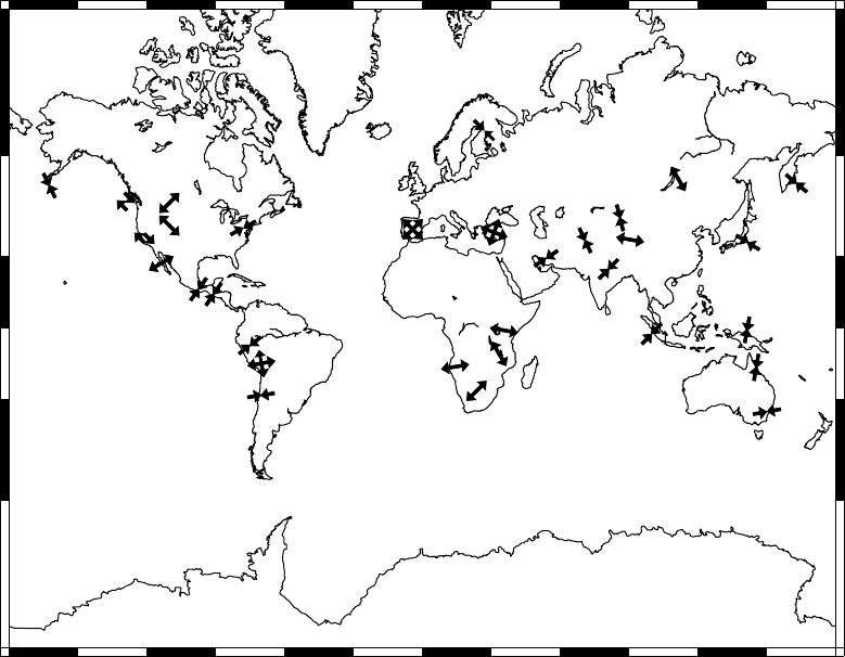
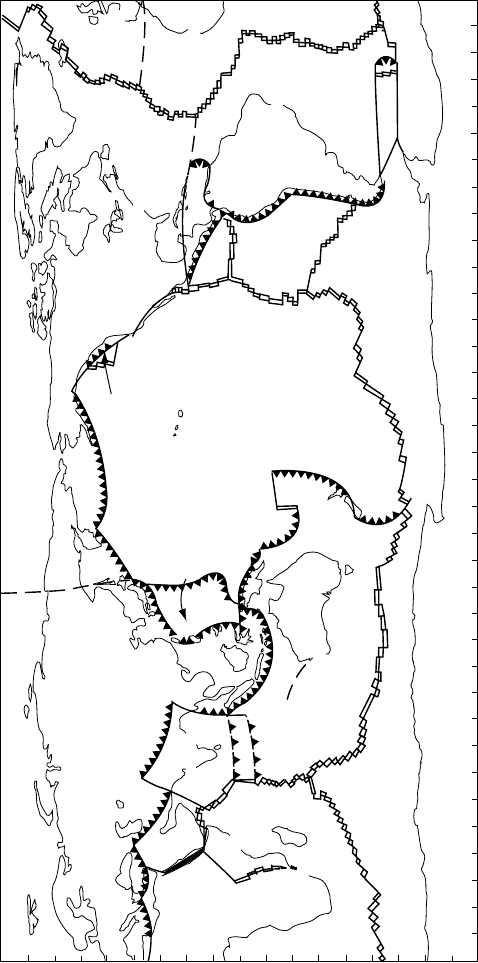
Figure 11.11 is a plot of stress regimes from
the world stress map (Reinecker et al, 2004),
which combines hydrofracture, overcoring and
borehole breakout measurements with earth-
quake focal mechanisms (Chapter 14) and geo-
logical indicators such as faulting type. Large
regions of the world exhibit coherent stress
directions. Diverging and converging arrows
represent regions of tension or compression,
respectively. Adjacent oppositely directed arrows
indicate strike-slip regions. For example, the
Aleutian subduction zone is a thrust regime,
whereas the San Andreas fault is strike-slip,
but further inland, the Basin and Range prov-
ince of west North America is a normal faulting
regime, as is Baja California, where crustal
extension is taking place. The major active con-
tinental rift zones of the world, which include
the East African rift in Kenya, the Rio Grande
rift in New Mexico, and Lake Baikal, Siberia, are
all in regions of extensional stress. The spatial
coherence of stress can be explained by a com-
bination of large-scale stresses from plate tec-
tonics and buoyancy stresses associated with
uplift, as considered further in Sections 13.4
and 13.6.
180° 210° 240° 270° 300° 330° 0° 30° 60° 90° 120° 150° 180°
180° 210° 240° 270° 300° 330° 0° 30° 60° 90° 120° 150° 180°
–60°
–6°
–30°
–3°
0° 0°
30°
30°
60°
60°
FIGURE 11.11 Selected details from the world stress map by Reinecker et al. (2004). Diverging arrows represent
regions of extension and converging arrows indicate compression. Anti-parallel pairs of arrows denote strike-slip
faulting.
162 DEFORMATION OF THE CRUST: ROCK MECHANICS
//FS2/CUP/3-PAGINATION/SDE/2-PROOFS/3B2/9780521873628C12.3D
–
163
– [163–180] 13.3.2008 11:21AM
12
Tectonics
12.1 Preamble
Seismicity (seismic activity) is a word coined by
Gutenberg and Richter (1941) to encompass
earthquake occurrences, their mechanisms,
magnitudes and especially their geographical
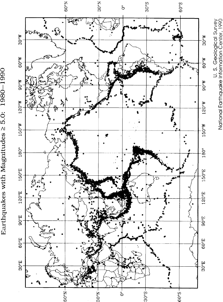
distribution. Although we have known for more
than 150 years that earthquakes are concentrated
in extended, but relatively narrow bands across
the Earth (Fig. 12.1), the pattern remained more
or less mysterious until it became a cornerstone
of the theory of plate tectonics in the 1950s and
1960s. According to this theory the surface of
the Earth is divided into almost rigid plates that
are in relative motion, with earthquakes occur-
ring mainly at the boundaries. Especially signifi-
cant in this connection are the deep focus
earthquakes, which mark the subduction zones
where cooled surface material plunges into the
mantle. They provide direct evidence of the deep,
convective motion that drives the plates.
Therearenowmorethan3000globallydistri-
buted seismological stations routinely contributing
data to the International Seismological Centre at
Thatcham, UK. Although they are unevenly dis-
tributed, they suffice to locate reliably all earth-
quakes of magnitude 5 or greater (the definition of
magnitude and its relationship to energy are dis-
cussed in Section 14.6). By restricting attention to
these events we can view the pattern of world
seismicity without a bias towards instrumented
areas. Earthquake epicentres (Fig. 12.1), that is
the surface points directly above the foci (hypo-
centres) where earthquakes actually occur, outline
the plates, which are identified in Fig. 12.2. Intra-
plate earthquakes also occur, although much less
frequently, demonstrating that the plates are
not completely rigid. However, plate deformation
is slight enough to neglect in calculations of their
relative motions. The pattern of mantle convec-
tion suggested by the distribution of earthquakes
in Fig. 12.1 is confirmed by studies of the first
motions of seismic waves (Section 14.4), which
are used to infer the relative motions of the plates
at their common boundaries.
The development of our understanding of
global scale tectonics was pioneered by paleo-
magnetism, which established the credibility of
continental drift (Section 25.6). Subsequently,
laser ranging to satellites (SLR), very long baseline
interferometry (VLBI), and, now much more
extensively, the global positioning system of sat-
ellites (GPS) have been used to show that the geo-
logically inferred relative motions of continental
blocks are on-going. Another crucial contribution
by paleomagnetism was the establishment of the
sequence of geomagnetic reversals (Section 25.4).
Fresh igneous crust produced at the spreading
ocean ridges is magnetized during or shortly
after its appearance and carries a record of the
field with it as it moves away from the ridges. This
has produced a series of linear ocean floor
magnetic anomalies parallel to the ridges, corre-
lated with the irregular alternations of the pol-
arity of the geomagnetic field seen in the
magnetism of continental rocks. For the last few
million years the reversals have been dated iso-
topically with sufficient accuracy to determine
the rates of ocean floor spreading from the
//FS2/CUP/3-PAGINATION/SDE/2-PROOFS/3B2/9780521873628C12.3D
–
164
– [163–180] 13.3.2008 11:21AM
FIGURE 12.1 Epicentres of earthquakes with magnitudes exceeding 5.0 that occurred in 1980–1990. National Earthquake Information
Center, US Geological Survey, Denver, courtesy of Susan K. Goter.
//FS2/CUP/3-PAGINATION/SDE/2-PROOFS/3B2/9780521873628C12.3D
–
165
– [163–180] 13.3.2008 11:21AM
0 10 20 30 40 50 60 70 80 90 100 110 120 130 140 150 160170180190200210220 230 240 250 260 270 280 290 300 310 320330340350360
–90
–80
–70
–60
–50
–40
–30
–20
–10
0
10
20
30
40
50
60
70
80
90
LONGITUDE (degrees)
LATITUDE (degrees)
PACIFIC
N. AMERICA
CARIB.
S AMERICA
EURASIA
AFRICA
SCOTIA
PHILIPPINE SEA
AUSTRALIA
?
INDIA
EURASIA
JUAN DE FUCA
COCOS
NAZCA
ANTARCTIC
NUBIA
SOMALIA
AFRICA
ARABIA
FIGURE 12.2 The Earth’s major plates. Subduction zones are represented by ‘shark’s teeth’ drawn on the over-riding plates and showing
the motion of the subducting plates beneath. Spreading centres are marked by double lines, but they are fragmented by transform faults
(single lines, as in Fig. 12.7). Broken lines mark uncertain boundaries.
//FS2/CUP/3-PAGINATION/SDE/2-PROOFS/3B2/9780521873628C12.3D
–
166
– [163–180] 13.3.2008 11:21AM
spacing of the magnetic stripes. For the period
back to 100 million years or so the magnetic
polarity time scale is established by the sea floor
anomalies, with the assumption that the spread-
ing rate is constant.
A third paleomagnetic observation with fund-
amental implications for tectonics is the motion
of the plates across volcanic ‘hot spots’ that are
anchored deep in the mantle. The idea of a man-
tle reference frame originated with observations
made in Hawaii. The presently active volcanos
are on Hawaii Island at the south-east end of
the island chain, latitude 198, an d at Lo ihi, a
submarine volcano immediately t o the SE of
that. The other islands in the chai n follow a
line in the north-west direction and have ages
that increase linearly with distance in that direc-
tion. Paleomagnetic measurements showed that
they were all formed at latitude 198, that is, at the
latitude of the present centre of volcanism. The
Pacific plate is moving across a more or less sta-
tionary mantle hot spot that produces a series of
volcanos, with their extinct and eroding edifices
steadily drifting north-west.
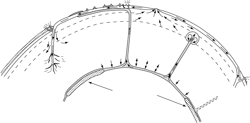
The concept of deep mantle convective plu-
mes, with local hot spots, such as Hawaii, as their
surface expressions, originated with Morgan
(1971) and has become an important component
of our understanding of mantle convection, as
illustrated in Fig. 12.3. It is not certain how many
there are because they are not all equally active.
The four most active occur in quite different sit-
uations. Hawaii and Reunion are oceanic islands,
Iceland sits astride the mid-Atlantic ridge and a
mid-continent hot spot occurs in Zaire, central
Africa. Yellowstone is a commonly cited example,
but appears to be physically different from the
others and may have a somewhat different cause.
Surface traces of several hot spots are recognized,
including some others on the Pacific plate in lines
roughly parallel to the Hawaiian chain. Those on
other plates have independent traces oriented
according to their plate motions. The apparent
fixity of the Hawaii hot spot invited the supposi-
tion that they are all more or less stationary with
respect to an immobile deep mantle and provide a
reference frame for plate tectonics. It is now clear
that they are moving with respect to one another,
but at speeds lower than the plate motions and
that they give an indication of convective motion
deep in the mantle. Particularly relevant is a check
on the relative motion of the two major oceanic
hot spots that are remote from plate boundaries,
Hawaii and Reunion (see Section 12.4).
The discoveries of paleomagnetism made
plate tectonics a convincingly quantitative
Asthenosphere
670 km
CORE
Crypto-continents
Established
plume
New
plume
Mid-ocean ridge
Hot spot
Volcanic chain
Subduction
zone
Island
arc
Andesite volcanos
Contine
nt
D"
Crypto-ocean
Extinct
plume
FIGURE 12.3 A pictorial cross-section of mantle convection.
166 TE C TO N I CS