Stephen L. Herman, Bennie Sparkman. Electricity and Controls for HVAC-R (6th edition)
Подождите немного. Документ загружается.

110 SECTION 2 Control Circuits
4 on one side and 5 on the other. One motor termi-
nal is numbered 5 and the other is numbered 6.
Now that the component parts have been num-
bered with the same numbers as those used on
the schematic, connection can be made easily and
quickly. To connect the circuit, connect all the
like numbers. For example, all the number 1s will
connect together, all the number 2s will connect
together, and so forth. The connected circuit is
shown in Figure 10–6.
DEVELOPMENT OF CIRCUIT 2
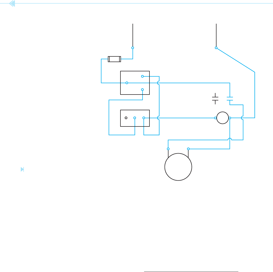
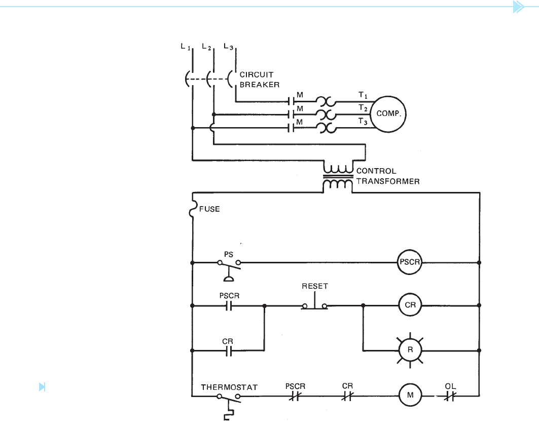
The schematic diagram for circuit 2 is shown in
Figure 10–7. Notice this schematic shows both
the control circuit and the motor connection. This
circuit is designed to turn off a compressor if the
pressure in the system reaches a predetermined
MAN terminal is numbered 4, and the AUTO ter-
minal is numbered 3. Now notice the same switch
on the wiring diagram. The common terminal is
numbered 2, the MAN terminal is numbered 4, and
the AUTO terminal is numbered 3. The thermostat
in the schematic has been numbered 3 on one ter-
minal and 4 on the other terminal. The thermostat
shown in the wiring diagram has three terminals.
One terminal is common, one terminal is marked
NC, and the other terminal is marked NO. This is
a common arrangement for many control com-
ponents. This shows that the thermostat is a single-
pole double-throw switch. Because the thermostat
shown in the schematic is normally open, the 3 will
be placed beside the common terminal, and the
4 will be placed beside the NO contact. Notice that
one of the contacts on FR relay is numbered 2 on
one side and 6 on the other side. FR coil is numbered
L
1
MOTOR
1
12
6
FR
45
6
2
5
N
5
C
A
2
3
M
4
NC C
THERMOSTAT
NO
43
Figure 10–6
Like numbers are connected.
(Source: Delmar/Cengage Learning)
UNIT 10 Developing Wiring Diagrams 111
the temperature decreases, the thermostat contacts
open and deenergize M coil. When M coil deener-
gizes, M contacts open and disconnect the compres-
sor from the power line. Notice that in the normal
action of this circuit, the compressor is controlled by
the thermostat.
Now assume that the thermostat contacts are
closed and that the compressor is connected to the
power line. Also assume that the pressure in the
system becomes too great and that the contacts
of the pressure switch close. When the pressure
switch contacts close,
PSCR (pressure switch
control relay
) coil energizes. This causes both
level. If the pressure becomes high enough to cause
the pressure switch contacts to close, the compres-
sor motor will not only be disconnected from the
power line, but a warning light will also be turned
on. Once the warning light has been turned on,
the system must be manually reset by the service
technician before the compressor can be restarted
by the thermostat. The operation of the circuit is as
follows:
When the thermostat contact closes, a circuit
is completed to M motor starter coil. When M
coil energizes, M contacts close and connect the
compressor to the three-phase power line. When
Figure 10–7
High pressure locks
compressor off. (Source: Delmar/
Cengage Learning)
112 SECTION 2 Control Circuits
thermostat if PSCR contact should reclose. Notice
that the warning light is connected in parallel
with the coil of CR relay. The warning light will be
turned on as long as CR relay coil is turned on. As
long as CR relay is energized, the compressor cannot
be restarted by the thermostat.
Now assume that the pressure in the system has
returned to normal and the problem that caused
the excessive pressure has been corrected. When
the pressure switch contact reopened, PSCR coil
deenergized and reset both PSCR contacts to their
normal position. When the service technician
presses the reset button, CR coil deenergizes and
both CR contacts return to their normal positions.
PSCR contacts to change position. When the nor-
mally closed PSCR contact opens, the circuit to M
coil is broken. This causes the compressor to be
disconnected from the line. When the normally
open PSCR contact closes, a circuit is completed to
CR (control relay) coil. When CR coil energizes,
both CR contacts change position. The normally
open CR contact closes to maintain a circuit to
CR coil in the event that the pressure in the system
decreases and opens the pressure switch contacts.
This would cause PSCR relay to deenergize and
return both PSCR contacts to their normal posi-
tion. The normally closed CR contact will open.
This prevents M coil from being energized by the
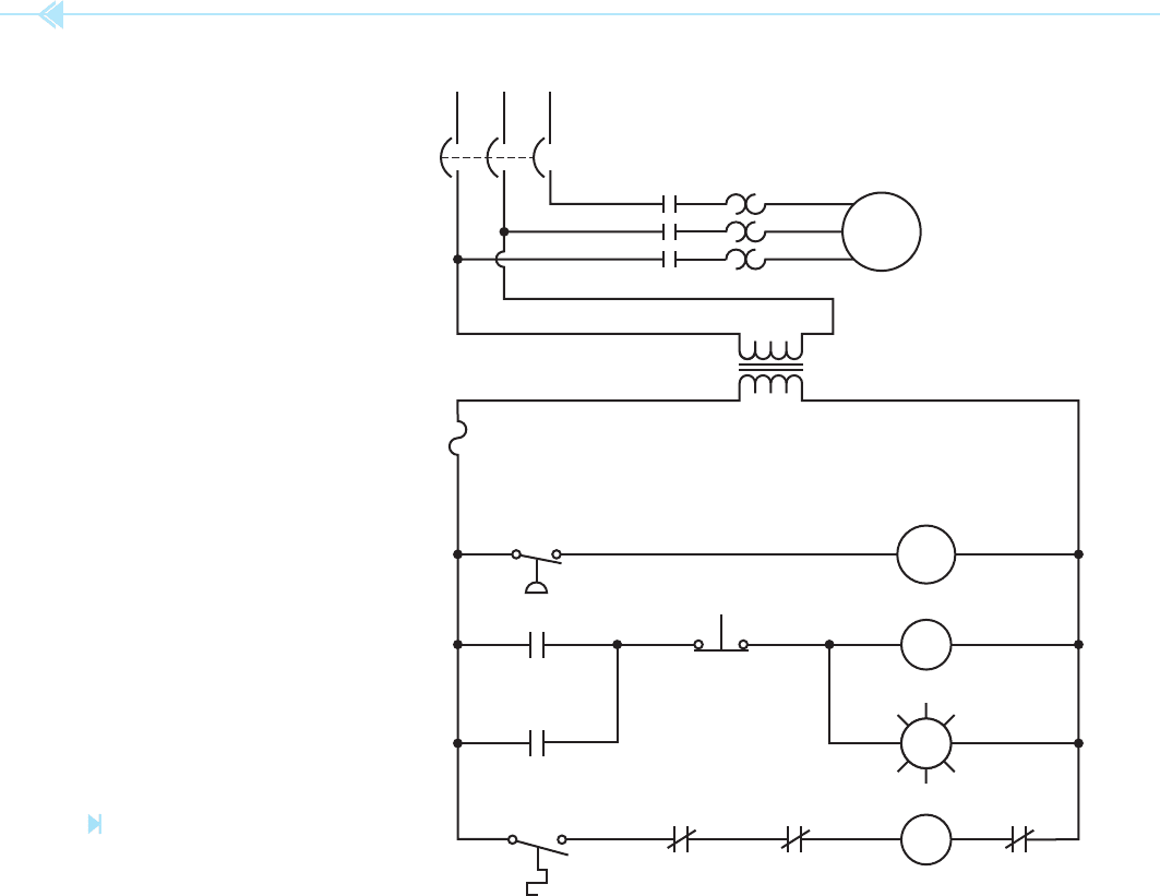
Figure 10–8
Schematic is numbered to aid in
circuit connection. (Source: Delmar/Cengage
Learning)
13
14
FUSE
PSCR
1111885
COMP.
T
2
1010
M
M
776
3
3
6
T
1
L
3
1212994
T
3
2
2
5
L
2
1
1
4
L
1
4
CONTROL
TRANSFORMER
CIRCUIT
BREAKER
5
16
13
14 15
PS
15 16
CR
14 18
PSCR
14
14
22
18
CR
22 21
PSCRTHERMOSTAT
18 17
RESET
17 16
17 16
RR
M
21 20
CR
191920 16
OL
UNIT 10 Developing Wiring Diagrams 113
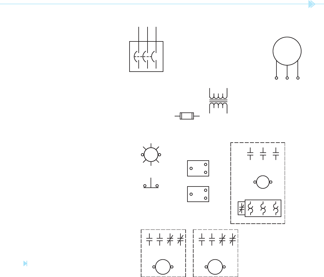
The control components are shown in
Figure 10–9. Notice that the numbers on the
components correspond with like numbers on
the schematic diagram. For example, on the
schematic diagram the primary of the control
transformer is numbered 4 and 5. The secondary
leads are numbered 13 and 16. Notice the same
is true on the wiring diagram. Note the number
of each component on the schematic and then
The circuit is now back in its original position and
ready for normal operation.
This schematic diagram is now being developed
into a wiring diagram. As before, the schematic is
numbered in the same manner as the rst example.
The numbered schematic is shown in Figure 10–8.
Notice that all components that are electrically tied
together have the same number. Also notice that no
number set has been used more than once.
Figure 10–9
Components are numbered the same in
the schematic. (Source: Delmar/Cengage Learning)
T
1
T
2
T
3
COMP.
1314
10 11 12
M
20 19
7
987
12 11 10
16
19
6
8
5
9
4
C
NC
14
15
NO
PS
C
NC
14
22
NOTEMP
4
13
5
16
17 16
RR
3
3
6
L
3
2
2
5
L
2
1
1
4
L
1
21
20
18
14
CR
17 16
22
21
18
14
PSCR
15 16
18 17

114 SECTION 2 Control Circuits
connecting like numbers. The circuit connection
is shown in Figure 10–10. Again, notice that
the wiring diagram appears to be completely
different from the schematic, but both are the
same electrically.
find the corresponding number beside the proper
component used on the wiring diagram.
Once the components of the wiring diagram have
been numbered with the same numbers as those
on the schematic, the circuit can be connected by
Figure 10–10
Connection is made by
connecting like numbers. (Source:
Delmar/Cengage Learning)
T
1
T
2
T
3
COMP.
1314
10
11 12
C
NC
14
15
NO
PS
C
NC
14
22
NOTEMP
4
13
5
16
17 16
RR
3
3
6
L
3
2
2
5
L
2
1
1
4
L
1
18 17
CR
17 16
PSCR
15 16
21
20
18
14
22
21
18
14
M
20 19
7
987
12 11 10
16
19
6
8
5
9
4

UNIT 10 Developing Wiring Diagrams 115
Wiring diagrams are generally developed from a schematic diagram.
All components in a schematic diagram are shown in their deenergized or off position.
Wire numbers are often placed on schematic diagrams to aid in connecting a wiring diagram.
Three basic rules for placing wire numbers on a schematic diagram are:
A. All components connected to the same line will receive the same number.
B. Any time a component is gone through, the number will change.
C. A set of numbers can be used only once.
KEY TERMS
SUMMARY
FR (fan relay)
PSCR (pressure switch control relay)
REVIEW QUESTIONS
Refer to Figure 10–1 for the following questions.
1. Explain the action of the circuit if the thermostat should fail to operate.
2. Explain the action of the circuit if FR contacts should become shorted together.
Refer to Figure 10–7 for the following questions.
3. Explain the action of the circuit if the overload (OL) contact should open.
4. Explain the action of the circuit if the pressure switch contacts should
become shorted.
5. Explain the action of the circuit if the CR coil should open.
This page intentionally left blank
SECTION 3
Motors

118
Because three-phase power is not available to small
business and residential locations, the air condition-
ing equipment for these areas is powered by single-
phase electric motors. The single-phase motors used
in air conditioning systems are generally one of two
types. These are the split-phase and the shaded-pole
induction motor.
SPLIT-PHASE MOTORS
Split-phase motors fall into three general clas-
si cations. These are:
1. The resistance-start induction-run
motor,
2. The capacitor-start induction-run
motor,
OBJECTIVES
After studying this unit the student should
be able to:
List the basic types of split-phase
motors
Discuss two-phase power
Discuss the operation of a resistance-
start induction run motor
Discuss the operation of a capacitor-
start induction run motor
Discuss the operation of a permanent-
split capacitor motor
Reverse the direction of rotation of a
split-phase motor
Connect dual voltage motors for
120- or 240-volt operation
Identify the terminal markings of an
oil-fi lled capacitor and discuss the
proper connection to a permanent
split-capacitor motor
Split-Phase
Motors
UNIT 11
UNIT 11 Split-Phase Motors 119
3. The permanent-split capacitor motor
(PSC). It should be noted that although all
permanent-split capacitor motors contain a
run capacitor, some are equipped with a sep-
arate starting capacitor to improve starting
torque. The motors with the separate starting
capacitor are often referred to as capacitor-
start capacitor-run motors.
Although all of these motors have different oper-
ating characteristics, they are similar in construc-
tion. Split-phase motors get their name from the
manner in which they operate. These motors oper-
ate on the principle of a rotating magnetic eld.
A rotating magnetic eld, however, cannot be pro-
duced with only one phase. Split-phase motors liter-
ally split single-phase power in order to imitate a
two-phase power system. A rotating magnetic eld
can be produced with two separate phases.
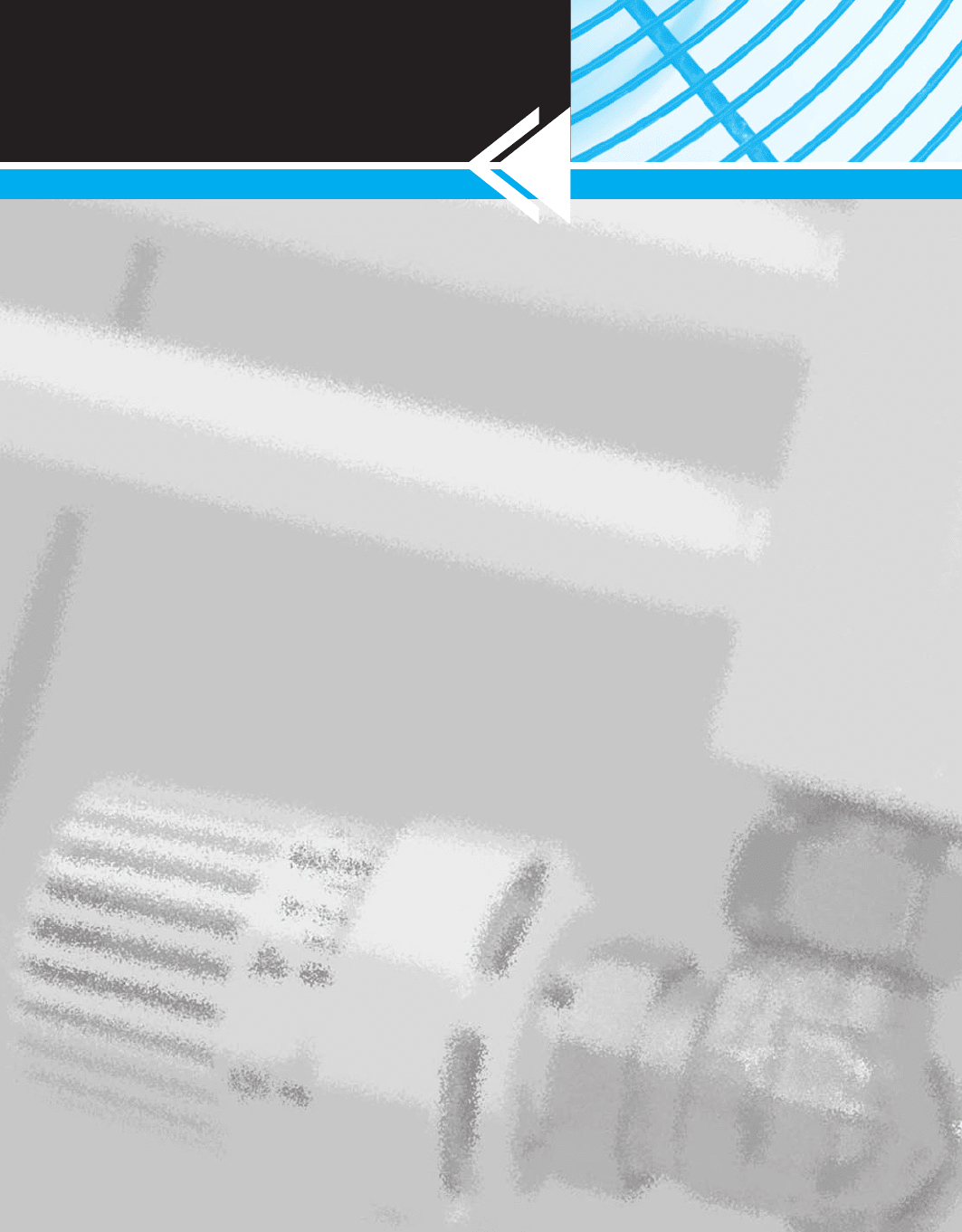
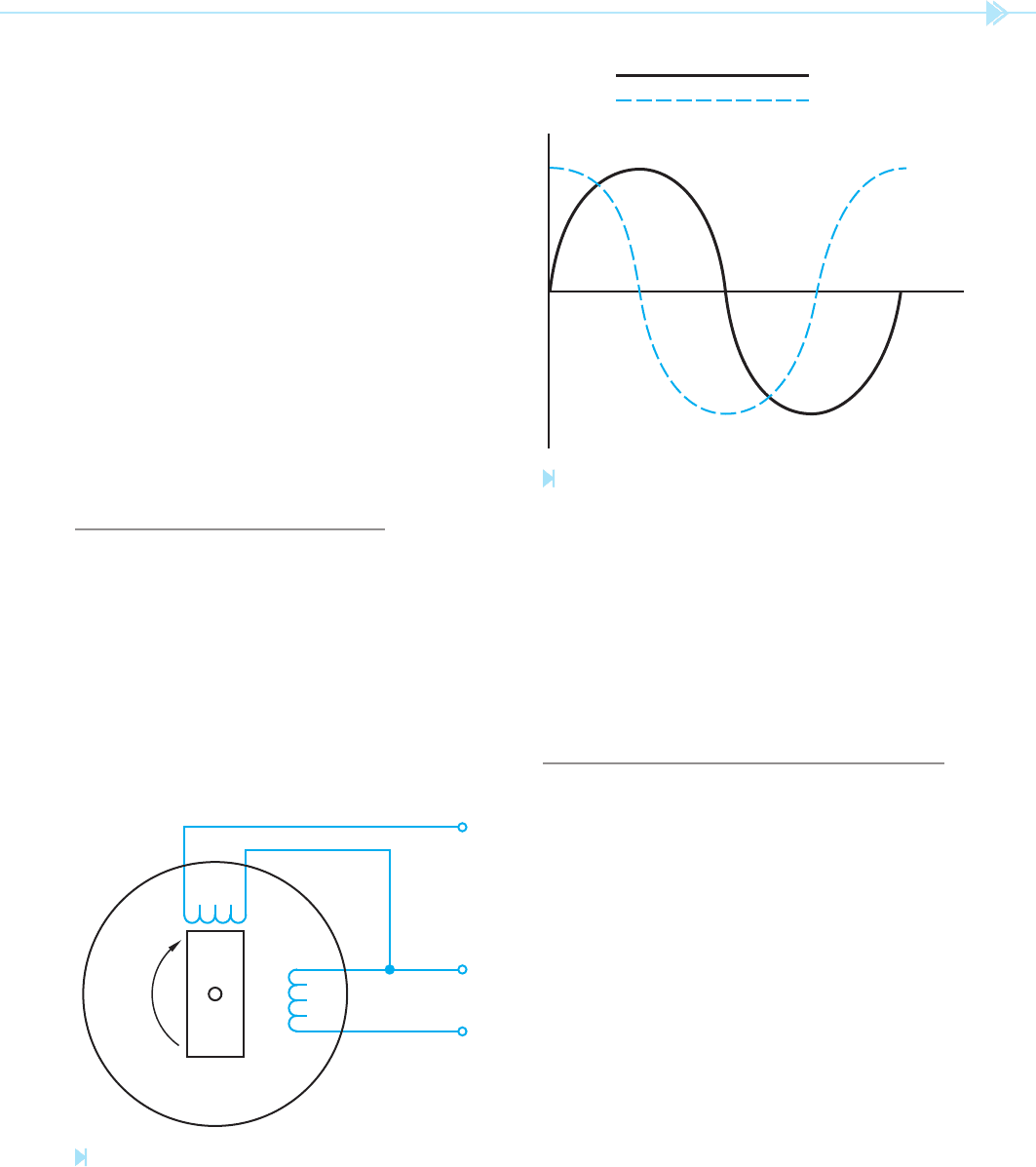
THE TWO-PHASE SYSTEM
In some parts of the world, two-phase power
is produced. A two-phase system is produced by
having an alternator with two sets of coils wound
90° out of phase with each other, Figure 11–1.
The voltages of a two-phase system are, therefore,
90° out of phase with each other, Figure 11–2. The
two out-of-phase voltages can be used to produce
a rotating magnetic eld. Because there have to
L
2
C
B
N
A
S
L
1
L
1
L
2
Figure 11–1
Two-phase alternator. (Source: Delmar/Cengage Learning)
Figure 11–2
Two-phase voltages are 90° out of phase with each
other. (Source: Delmar/Cengage Learning)
be two voltages or currents out of phase with each
other to produce a rotating magnetic eld, single-
phase motors use two separate windings and create
a phase difference between the currents in each of
these windings. These motors literally “split” one
phase and produce a second phase, hence the name
split-phase motor.
RESISTANCE-START INDUCTION-
RUN AND CAPACITOR-START
INDUCTION-RUN MOTORS
Resistance-start induction-run and capacitor-start
induction-run motors are very similar in construc-
tion. The stator winding of both motors contains
both a start winding and a run winding. The
start winding is made of smaller wire and placed
higher in the metal core material than the run wind-
ing, as shown in Figure 11–3. Since the start winding
is made with smaller wire than the run winding, it
will exhibit a higher resistance than the run wind-
ing. Placing the run winding deeper in the metal
core material causes it to exhibit a greater amount
of inductance that the start winding. Electrically,
the winding appears similar to the circuit shown in
Figure 11–4. The stator is constructed in this