Stevenson J. Power system analysis
Подождите немного. Документ загружается.

716
CHAPTER
1
6 POWER SYSTEM STABILITY
b
(
a
) Pe nd ulum
I'
I
\
I
\
I ,
I
\
I
\
I
\
a
,-l
\-.
�
< l
�
-. - �.
b
(Ii) Pendulum on disk
FIGURE 16.7
Pendulum and r()t�ttillg disk to il
lustrate a ru tm swinging with re
spect to ;In infinite bus.
unstable equilibrium since Sf) is neg:tlive there. So, this point is not a v�tlid
operating point.
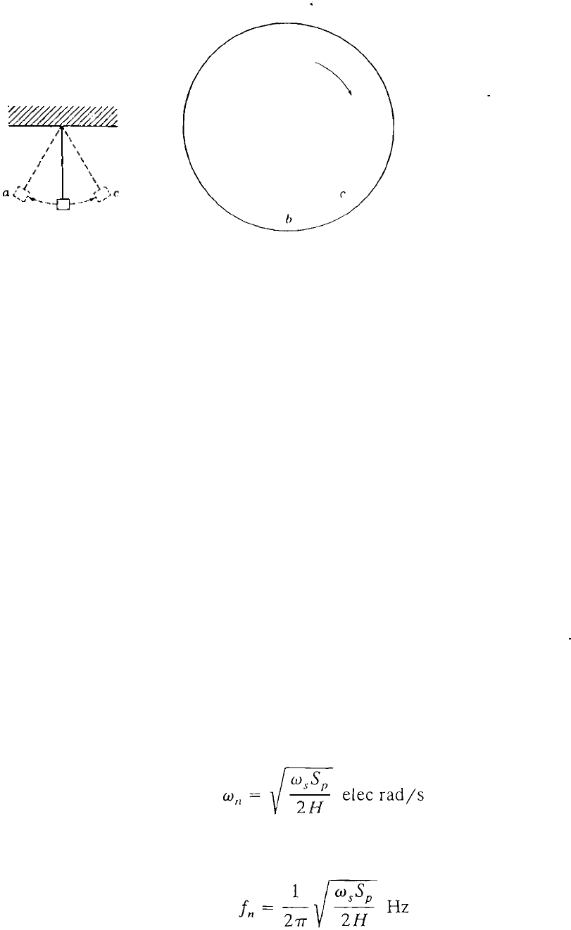
The changing position of the generator rotor swinging with respect to the
innite bus may be visualized by an analogy. Consider a pendulum swinging
fr
om a pivot on a stationary frame, as shown in Fig. 16.7(a). Points a and c are
the
maximum points of the oscillation of the pendulum about the equilibrium
point b. Damping will eventually bring the pendulum to rest at b. Now imagine
a disk rotating in a clockwise direction about the pivot of the pendulum, as
shown in Fig. 16.7(b), and superimpose the motion of the pendulum on the
motion of the disk. When the pendulum is moving from a to c, the combined
angular velocity is slower than that of the disk. When the pendulum is moving
from c to a, the combined angular velocity is faster than that of the disk. At
points a and c the angular velocity of the pendulum alone is zero and the
combined angular velocity equals that of the disk. If the angular veloci ty of
the disk corresponds to the synchronous speed of the rotor, and if the motion of
the pendulum alone represents the swinging of the rotor with respect to an
innite bus, the superimposed motion of the pe ndulum on that of the disk
represents the actual angular motion of the rotOL
From the above discussion we cone! ude that the solut ion of Eq. (] 6.48)
represents sinusoidal oscillations, provided the synchronizing power coefcien t
S
p is positive. The angular frequency of the undamped oscillations is given by
(16.49)
which corresponds to a frequency of oscillation given by
(
16.50)
Example 16.6. The machine of Example 16.3 is operating at 0 = 28.44° when it is
subjected to a slight temporary electrical system disturbance. Determ
i
ne the

16.6 EQUAAREA CRIRION OF ABIU
717
frequency and period of oscillation of the machine rotor if the disturbance is
removed before the prime mover responds. Take H = 5 /MVA.
Solution. The applicable swing equation is Eq. (16.48) and the synchronizing power
coecient at the opera ting poin t is
S
p
=
2.l0cos28.44° = 1.8466
The angular frequency of oscillation is therefore
w � / w,Sp �
)
377 X 1.8466
n
2H
V
2 X 5
= 8.343 e1ec rad/s
The corresponding frequency of oscillation is
8.343
f
=
= 133 Hz
n
2
.
and the period of oscillation is
1
T = -= 0.753 S
f
,1
The above example is an important one from the practical viewpoint since it
indicates the order of magnitude of the frequencies which can be superimposed
upon the nominal 60-Hz frequency in a large system having many intercon
nected machines. As load on the system changes randomly throughout the day,
intermachine oscillations involving frequencies of the order of 1 Hz tend to
arise, but these are quickly damped out by the various damping inuences
caused by the prime mover, the system loads, and the machine itself. It is
worthwhile to note that even if the transmission system in our example contains
resistance, nonetheless, the swinging of the rotor is harmonic and undamped.
Problem 16.8 examines the eect of resistance on the synchronizing power
coecient and the frequency of oscillations. In a later section we again discuss
the concept of synchronizing coecients. In the next section we examine a
method of determining stability under transient conditions caused by large
disturbances.
16.6 EQUAL-AREA CRITERION
OF STABILITY
In Sec. 16.4 we developed swing equations which are nonlinear in nature.
Formal solutions of such equations cannot be explicitly found. Even in the case
of a single machine swinging with respect to an innite bus, it is very dicult to
obtain literal-form solutions, and computer methods are therefor
�
noally
718
CHAPTER 16 POWER SYSTEM STABILITY
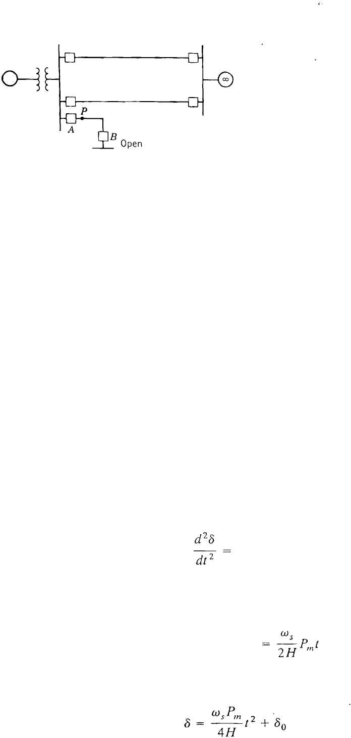
FIGU 16.8
One-line diagram of the syslem of Fig. 16.4
with the addition of a short transmission line.
used. To examine the stability of a two-machine system without solving the
swing equation, a direct approach is possible as now discussed.
The system shown in Fig. 16.8 is the same as that considered previously
except for the addition of a short transmission line. Initial ly , circuit breaker A is
considered to be closeu while circuit bre;lKer
- 2008 — 2026 «СтудМед»