Valacich J., George J., Hoffer J.A. Essentials of Systems Analysis and Design
Подождите немного. Документ загружается.

Chapter Preview . . .
In Chapter 7 you learned how to represent an
organization’s data graphically using an entity-
relationship (E-R) diagram and Microsoft Visio.
In this chapter, you learn guidelines for clear and
efficient data files and about logical and physical
database design. It is likely that the human inter-
face and database design steps will happen in
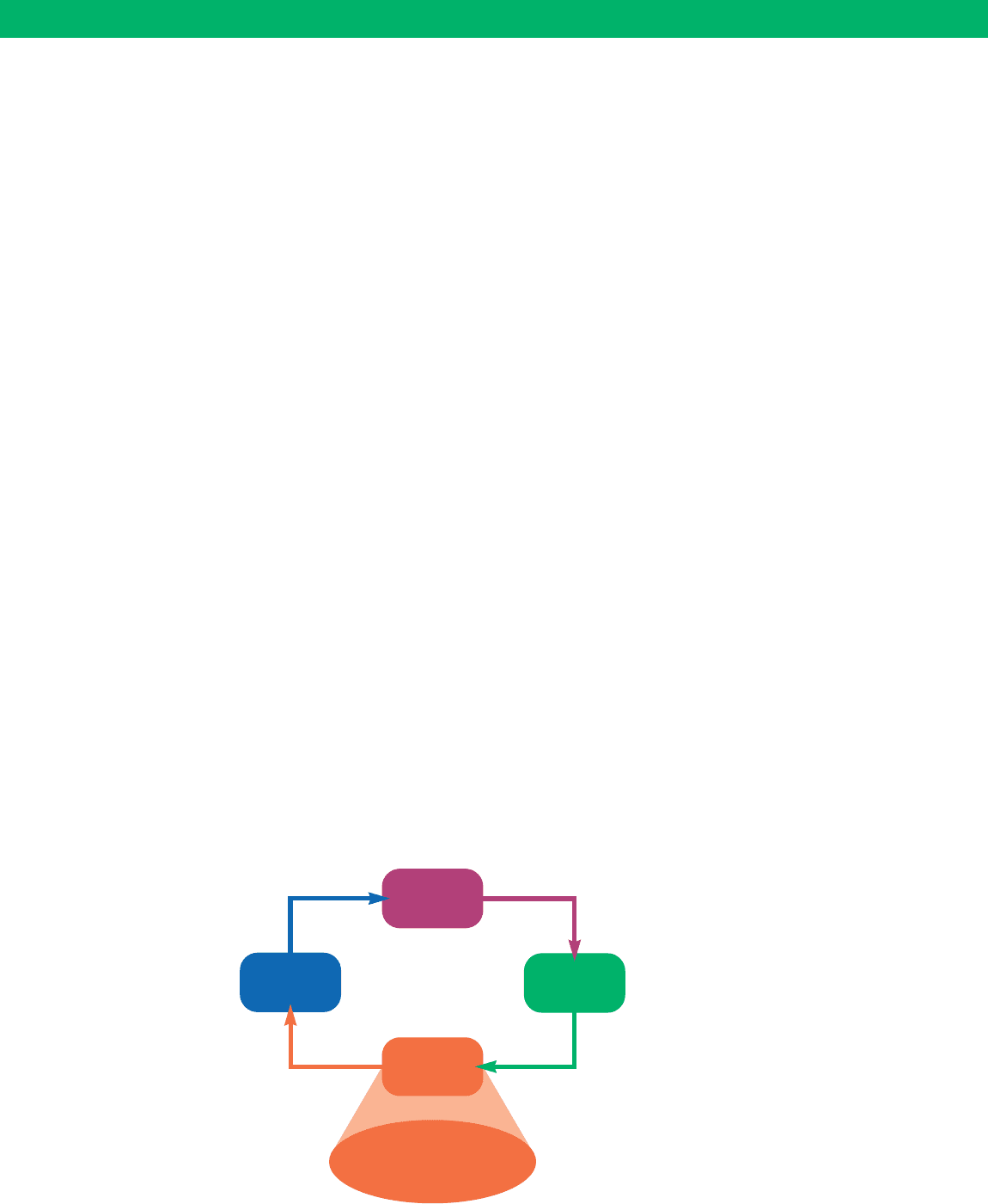
parallel, as illustrated in the SDLC in Figure 9-1.
Logical and physical database design has five
purposes:
1. Structure the data in stable structures that
are not likely to change over time and that
have minimal redundancy.
2. Develop a logical database design that
reflects the actual data requirements that
exist in the forms (hard copy and computer
displays) and reports of an information
system. For this reason, database design is
often done in parallel with the design of the
human interface of an information system.
3. Develop a logical database design from
which we can do physical database design.
Because most information systems today
use relational database management
systems, logical database design usually
uses a relational database model, which
represents data in simple tables with
common columns to link related tables.
4. Translate a relational database model into a
technical file and database design.
5. Choose data-storage technologies (such as
hard disk, CD-ROM, or flash disk) that will
efficiently, accurately, and securely process
database activities.
The implementation of a database (i.e., creat-
ing and loading data into files and databases) is
done during the next phase of the systems devel-
opment life cycle. Because implementation is
technology specific, we address implementation
issues only at a general level in Chapter 10.
273
Designing the Human Interface
Designing Databases
✓
Systems
Planning and
Selection
Systems
Analysis
Systems
Design
Systems
Implementation
and Operation
SDLC
FIGURE 9-1
Systems development life cycle.
Systems analysts design
databases during the systems
design phase. Database design
typically occurs in parallel with
other design steps.
274 Part IV Systems Design
Database Design
File and database design occurs in two steps. You begin by developing a logical
database model, which describes data using a notation that corresponds to a
data organization used by a database management system. This system soft-
ware is responsible for storing, retrieving, and protecting data (such as
Microsoft Access, Oracle, or SQL Server). The most common style for a logical
database model is the relational database model. Once you develop a clear and
precise logical database model, you are ready to prescribe the technical speci-
fications for computer files and databases in which to store the data ultimately.
A physical database design provides these specifications.
You typically do logical and physical database design in parallel with other
systems design steps. Thus, you collect the detailed specifications of data nec-
essary for logical database design as you design system inputs and outputs. Log-
ical database design is driven not only from the previously developed E-R data
model for the application but also from form and report layouts. You study data
elements on these system inputs and outputs and identify interrelationships
among the data. As with conceptual data modeling, the work of all systems
development team members is coordinated and shared through the project dic-
tionary or repository. The designs for logical databases and system inputs and
outputs are then used in physical design activities to specify to computer pro-
grammers, database administrators, network managers, and others how to
implement the new information system. We assume for this text that the design
of computer programs and distributed information processing and data networks
are topics of other courses, so we concentrate on the aspect of physical design
most often undertaken by a systems analyst—physical file and database design.
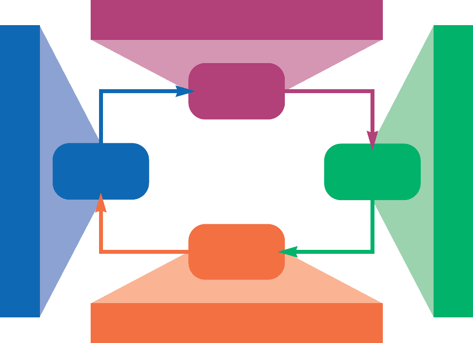
The Process of Database Design
Figure 9-2 shows that database modeling and design activities occur in all
phases of the systems development process. In this chapter we discuss meth-
ods that help you finalize logical and physical database designs during the design
phase. In logical database design you use a process called normalization, which
is a way to build a data model that has the properties of simplicity, nonredun-
dancy, and minimal maintenance.
In most situations, many physical database design decisions are implicit or
eliminated when you choose the data-management technologies to use with the
application. We concentrate on those decisions you will make most frequently
and use Microsoft Access to illustrate the range of physical database design
parameters you must manage. The interested reader is referred to Hoffer,
Ramesh, and Topi (2011) for a more thorough treatment of techniques for logical
and physical database design.
Four steps are key to logical database modeling and design:
1. Develop a logical data model for each known user interface (form and
report) for the application, using normalization principles.
2. Combine normalized data requirements from all user interfaces into one
consolidated logical database model; this step is called view integration.
3. Translate the conceptual E-R data model for the application, developed
without explicit consideration of specific user interfaces, into normalized
data requirements.
4. Compare the consolidated logical database design with the translated
E-R model and produce, through view integration, one final logical
database model for the application.
During physical database design, you use the results of these four key logical
database design steps. You also consider definitions of each attribute; descriptions
Chapter 9 Designing Databases 275
Enterprise data model (E-R with only entities)
Conceptual data model (E-R with only entities for specific project)
•
•
Database and file definitions (DBMS-specific code)
Data model evolution
•
•
Logical data model (relational)
Physical file and database design (file organizations)
Conceptual data models (E-R with attributes)
•
•
•
Systems
Planning and
Selection
Systems
Analysis
Systems
Design
Systems
Implementation
and Operation
SDLC
FIGURE 9-2
Relationship between data modeling and the systems development life cycle.
of where and when data are entered, retrieved, deleted, and updated; expecta-
tions for response time and data integrity; and descriptions of the file and data-
base technologies to be used. These inputs allow you to make key physical
database design decisions, including the following:
1. Choosing the storage format (called data type) for each attribute from the
logical database model; the format is chosen to minimize storage space
and to maximize data quality. Data type involves choosing length, coding
scheme, number of decimal places, minimum and maximum values, and
potentially many other parameters for each attribute.
2. Grouping attributes from the logical database model into physical records
(in general, this is called selecting a stored record, or data structure).
3. Arranging related records in secondary memory (hard disks and magnetic
tapes) so that individual and groups of records can be stored, retrieved,
and updated rapidly (called file organizations). You should also consider
protecting data and recovering data after errors are found.
4. Selecting media and structures for storing data to make access more
efficient. The choice of media affects the utility of different file
organizations. The primary structure used today to make access to data
more rapid is key indexes, on unique and nonunique keys.

Primary key
An attribute whose value is
unique across all occurrences of
a relation.
276 Part IV Systems Design
In this chapter we show how to do each of the logical database design steps
and discuss factors to consider in making each physical file and database design
decision.
Deliverables and Outcomes
During logical database design, you must account for every data element on a
system input or output—form or report—and on the E-R model. Each data ele-
ment (like customer name, product description, or purchase price) must be a
piece of raw data kept in the system’s database, or in the case of a data element
on a system output, the element can be derived from data in the database.
Figure 9-3 illustrates the outcomes from the four-step logical database design
process. Figures 9-3A and 9-3B (step 1) contain two sample system outputs for
a customer order processing system at Pine Valley Furniture. A description of
the associated database requirements, in the form of what we call normalized
relations, is listed below each output diagram. Each relation (think of a relation
as a table with rows and columns) is named, and its attributes (columns) are
listed within parentheses. The primary key attribute—that attribute whose
value is unique across all occurrences of the relation—is indicated by an
underline, and an attribute of a relation that is the primary key of another rela-
tion is indicated by a dashed underline.
In Figure 9-3A data are shown about customers, products, and the customer
orders and associated line items for products. Each of the attributes of each
relation either appears in the display or is needed to link related relations. For
example, because an order is for some customer, an attribute of ORDER is the
associated Customer_ID. The data for the display in Figure 9-3B are more com-
plex. A backlogged product on an order occurs when the amount ordered
(Order_Quantity) is less than the amount shipped (Ship_Quantity) for invoices
associated with an order. The query refers to only a specified time period, so the
Order_Date is needed. The INVOICE Order_Number links invoices with the
associated order.
Figure 9-3C (step 2) shows the result of integrating these two separate sets
of normalized relations. Figure 9-3D (step 3) shows an E-R diagram for a cus-
tomer order processing application that might be developed during concep-
tual data modeling along with equivalent normalized relations. Figure 9-3E
(step 4) shows a set of normalized relations that would result from reconcil-
ing the logical database designs of Figures 9-3C and 9-3D. Normalized
relations like those in Figure 9-3E are the primary deliverable from logical
database design.
Finally, Figure 9-3F shows the E-R diagram drawn in Microsoft Visio. Visio
actually shows the tables and relationships between the tables from the nor-
malized relations. Thus, the associative entities, LINE ITEM and SHIPMENT,
are shown as entities on the Visio diagram; we do not place relationship names
on either side of these entities on the Visio diagram because these represent
associative entities. Visio also shows for these entities the primary keys of the
associated ORDER, INVOICE, and PRODUCT entities. Also, note that the lines
for the Places and Bills relationships are dashed. This Visio notation indicates
that ORDER and INVOICE have their own primary keys that do not include the
primary keys of CUSTOMER and ORDER, respectively (what Visio calls non-
identifying relationships). Because LINE ITEM and SHIPMENT both include in
their primary keys the primary keys of other entities (which is common for
associative entities), the relationships around LINE ITEM and SHIPMENT are
identifying, and hence the relationship lines are solid.
It is important to remember that relations do not correspond to computer
files. In physical database design, you translate the relations from logical data-
base design into specifications for computer files. For most information

CUSTOMER(Customer_ID,Name)
PRODUCT(Product_ID)
INVOICE(Invoice_Number,Invoice_Date,Order_Number)
ORDER(Order_Number,Customer_ID,Order_Date)
LINE ITEM(Order_Number,Product_ID,Order_Quantity)
SHIPMENT(Product_ID,Invoice_Number,Ship_Quantity)
Chapter 9 Designing Databases 277
HIGHEST VOLUME CUSTOMER
ENTER PRODUCT ID.: M128
START DATE: 11/01/2012
END DATE: 12/31/2012
– – – – – – – – – – – – – – – – – – – – –
CUSTOMER ID.: 1256
NAME: Commonwealth Builder
VOLUME: 30
This inquiry screen shows the customer with the largest volume total sales of a
specified product during an indicated time period.
Relations:
CUSTOMER(Customer_ID,Name)
ORDER(Order_Number,Customer_ID,Order_Date)
PRODUCT(Product_ID)
LINE ITEM(Order_Number,Product_ID,Order_Quantity)
- - - - - - - -
FIGURE 9-3
Simple example of logical data
modeling: (A) Highest-volume
customer query screen, (B) Backlog
summary report, (C) Integrated set
of relations, (D) Conceptual data
model and transformed relations,
(E) Final set of normalized
relations, (F) Microsoft Visio E-R
diagram.
BACKLOG SUMMARY REPORT
11/30/2012
PAGE 1
BACKLOG
QUANTITY PRODUCT ID
B381
B975
B985
E125
M128
0
0
6
30
2
……
This report shows the unit volume of each product that has been ordered less than
amount shipped through the specified date.
Relations:
PRODUCT(Product_ID)
LINE ITEM(Product_ID,Order_Number,Order_Quantity)
ORDER(Order_Number,Order_Date)
SHIPMENT(Product_ID,Invoice_Number,Ship_Quantity)
INVOICE(Invoice_Number,Invoice_Date,Order_Number)
- - - - - - - - -
A
B
C
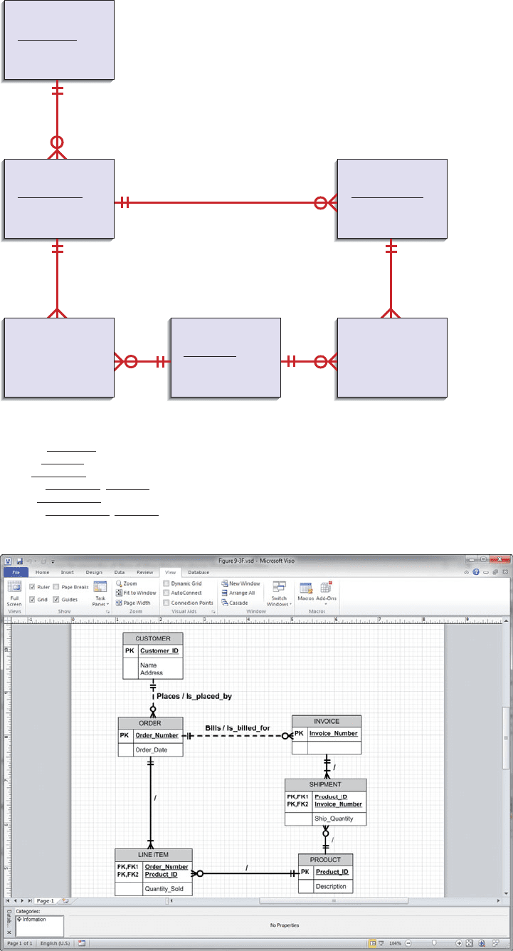
CUSTOMER(Customer_ID,Name,Address)
PRODUCT(Product_ID,Description)
ORDER(Order_Number,Customer_ID,Order_Date)
LINE ITEM(Order_Number,Product_ID,Order_Quantity)
INVOICE(Invoice_Number,Order_Number,Invoice_Date)
SHIPMENT(Invoice_Number,Product_ID,Ship_Quantity)
_ _ _ _ _ _ _ _
_ _ _ _ _ _ _ _ _
278 Part IV Systems Design
LINE ITEM
Order_Quantity
PRODUCT
Product_ID
Description
Places
Bills
ORDER
Order_Number
Order_Date
CUSTOMER
Customer_ID
Name
Address
Invoice_Number
SHIPMENT
Ship_Quantity
INVOICE
D
E
F
FIGURE 9-3
(
continued
)
Chapter 9 Designing Databases 279
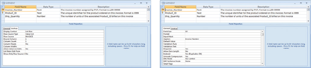
FIGURE 9-4
Definition of SHIPMENT table in Microsoft Access: (A) Table with invoice_number properties, (B) Invoice_number lookup properties.
systems, these files will be tables in a relational database. These specifications
are sufficient for programmers and database analysts to code the definitions of
the database. The coding, done during systems implementation, is written in
special database definition and processing languages, such as Structured Query
Language (SQL), or by filling in table definition forms, such as with Microsoft
Access. Figure 9-4 shows a possible definition for the SHIPMENT relation from
Figure 9-3E using Microsoft Access. This display of the SHIPMENT table defi-
nition illustrates choices made for several physical database design decisions.
쐍 All three attributes from the SHIPMENT relation, and no attributes
from other relations, have been grouped together to form the fields of
the SHIPMENT table.
쐍 The Invoice_Number field has been given a data type of Text, with a
maximum length of 10 characters.
쐍 The Invoice_Number field is required because it is part of the primary
key for the SHIPMENT table (the value that makes every row of the
SHIPMENT table unique is a combination of Invoice_Number and
Product_ID).
쐍 An index is defined for the Invoice_Number field, but because there
may be several rows in the SHIPMENT table for the same invoice
(different products on the same invoice), duplicate index values are
allowed (so Invoice_Number is what we will call a secondary key).
쐍 The Invoice_Number, because it references the Invoice_Number from
the INVOICE table, is defined as a Lookup to the first column
(Invoice_Number) of the INVOICE table; in this way, all values that
are placed in the Invoice_Number field of the SHIPMENT table must
correspond to a previously entered invoice.
Many other physical database design decisions were made for the SHIPMENT
table, but they are not apparent on the display in Figure 9-4. Further, this table
is only one table in the PVF Order Entry database, and other tables and struc-
tures for this database are not illustrated in this figure.
Relational Database Model
Many different database models are in use and are the basis for database tech-
nologies. Although hierarchical and network models have been popular in the
past, they are not often used today for new information systems. Object-
oriented database models are emerging but are still not common. The vast
majority of information systems today use the relational database model.
A
B

Well-structured relation
(or table)
A relation that contains a
minimum amount of redundancy
and allows users to insert,
modify, and delete the rows
without errors or inconsistencies.
Relation
A named, two-dimensional table
of data. Each relation consists of
a set of named columns and an
arbitrary number of unnamed
rows.
Relational database
model
Data represented as a set of
related tables or relations.
280 Part IV Systems Design
EMPLOYEE1
Emp_ID Name Dept Salary
100 Margaret Simpson Marketing 42,000
140 Allen Beeton Accounting 39,000
110 Chris Lucero Info Systems 41,500
190 Lorenzo Davis Finance 38,000
150 Susan Martin Marketing 38,500
FIGURE 9-5
EMPLOYEE1 relation with
sample data.
The relational database model represents data in the form of related tables
or relations. A relation is a named, two-dimensional table of data. Each rela-
tion (or table) consists of a set of named columns and an arbitrary number of
unnamed rows. Each column in a relation corresponds to an attribute of that
relation. Each row of a relation corresponds to a record that contains data
values for an entity.
Figure 9-5 shows an example of a relation named EMPLOYEE1. This relation
contains the following attributes describing employees: Emp_ID, Name, Dept, and
Salary. The table contains five sample rows, corresponding to five employees.
You can express the structure of a relation by a shorthand notation in which
the name of the relation is followed (in parentheses) by the names of the attri-
butes in the relation. The identifier attribute (called the primary key of the re-
lation) is underlined. For example, you would express EMPLOYEE1 as follows:
Employee (Emp_ID, Name, Dept, Salary)
Not all tables are relations. Relations have several properties that distinguish
them from nonrelational tables:
1. Entries in cells are simple. An entry at the intersection of each row and
column has a single value.
2. Entries in columns are from the same set of values.
3. Each row is unique. Uniqueness is guaranteed because the relation has a
nonempty primary key value.
4. The sequence of columns can be interchanged without changing the
meaning or use of the relation.
5. The rows may be interchanged or stored in any sequence.
Well-Structured Relations
What constitutes a well-structured relation (or table)? Intuitively, a well-
structured relation contains a minimum amount of redundancy and allows
users to insert, modify, and delete the rows in a table without errors or incon-
sistencies. EMPLOYEE1 (Figure 9-5) is such a relation. Each row of the table
contains data describing one employee, and any modification to an employee’s
data (such as a change in salary) is confined to one row of the table.
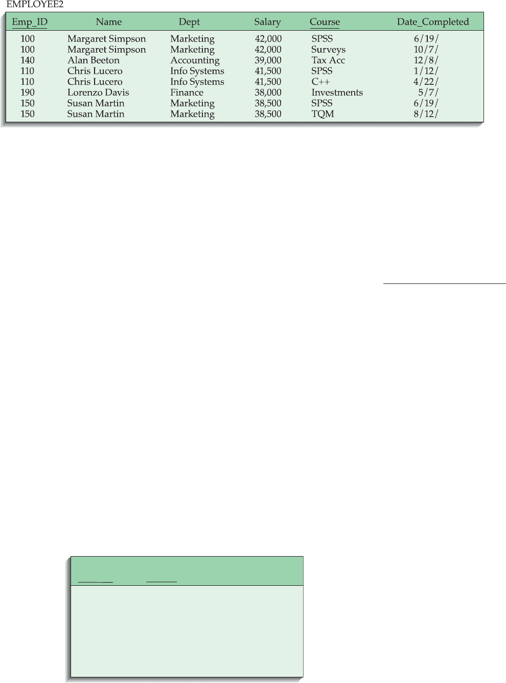
In contrast, EMPLOYEE2 (Figure 9-6) contains data about employees and the
courses they have completed. Each row in this table is unique for the combina-
tion of Emp_ID and Course, which becomes the primary key for the table. It is
not a well-structured relation, however. If you examine the sample data in the
table, you notice a considerable amount of redundancy. For example, the
Emp_ID, Name, Dept, and Salary values appear in two separate rows for
employees 100, 110, and 150. Consequently, if the salary for employee 100
changes, we must record this fact in two rows (or more, for some employees).
The problem with this relation is that it contains data about two entities:
EMPLOYEE and COURSE. You will learn to use principles of normalization
to divide EMPLOYEE2 into two relations. One of the resulting relations is
Normalization
The process of converting
complex data structures into
simple, stable data structures.
Chapter 9 Designing Databases 281
2012
2012
2012
2012
2012
2012
2012
2012
FIGURE 9-6
Relation with redundancy.
EMP COURSE
Date_
Emp_ID Course Completed
100 SPSS 6/19/2012
100 Surveys 10/7/2012
140 Tax Acc 12/8/2012
110 SPSS 1/22/2012
110 C++ 4/22/2012
190 Investments 5/7/2012
150 SPSS 6/19/2012
150 TQM 8/12/2012
FIGURE 9-7
EMP COURSE relation.
EMPLOYEE1 (Figure 9-5). The other we will call EMP COURSE, which appears
with sample data in Figure 9-7. The primary key of this relation is the combina-
tion of Emp_ID and Course (we emphasize this by underlining the column
names for these attributes).
Normalization
We have presented an intuitive discussion of well-structured relations, however,
we need rules and a process for designing them. Normalization is a process for
converting complex data structures into simple, stable data structures. For ex-
ample, we used the principles of normalization to convert the EMPLOYEE2 table
with its redundancy to EMPLOYEE1 (Figure 9-5) and EMP COURSE (Figure 9-7).
Rules of Normalization
Normalization is based on well-accepted principles and rules. The many nor-
malization rules, are too numerous to cover in this text (see Hoffer, Ramesh,
and Topi [2011] for more complete coverage). Besides the five properties of
relations outlined previously, two other rules are frequently used.
1. Second normal form (2NF). Each nonprimary key attribute is identified
by the whole key (what we call full functional dependency).
2. Third normal form (3NF). Nonprimary key attributes do not depend on
each other (what we call no transitive dependencies).
The result of normalization is that every nonprimary key attribute depends
upon the whole primary key and nothing but the primary key. We discuss second
and third normal form in more detail next.

Second normal form
(2NF)
A relation for which every
nonprimary key attribute is
functionally dependent on the
whole primary key.
Functional dependency
A particular relationship between
two attributes. For a given
relation, attribute B is functionally
dependent on attribute A if, for
every valid value of A, that value
of A uniquely determines the
value of B. The functional
dependence of B on A is
represented by A
: B.
A
X
Y
Z
Y
B
U
X
Y
Z
C
X
Z
Y
W
D
Y
X
Y
Z
EXAMPLE
FIGURE 9-8
EXAMPLE relation.
282 Part IV Systems Design
Functional Dependence and Primary Keys
Normalization is based on the analysis of functional dependence. A functional
dependency is a particular relationship between two attributes. In a given rela-
tion, attribute B is functionally dependent on attribute A if, for every valid value
of A, that value of A uniquely determines the value of B. The functional depend-
ence of B on A is represented by an arrow, as follows: A
:
B (e.g., Emp_ID
:
Name
in the relation of Figure 9-5). Functional dependence does not imply mathemat-
ical dependence—that the value of one attribute may be computed from the
value of another attribute; rather, functional dependence of B on A means that
there can be only one value of B for each value of A. Thus, for a given Emp_ID
value, only one Name value can be associated with it; the value of Name, how-
ever, cannot be derived from the value of Emp_ID. Other examples of functional
dependencies from Figure 9-3B are in ORDER, Order_Number
: Order_Date,
and in INVOICE, Invoice_Number
: Invoice_Date and Order_Number.
An attribute may be functionally dependent on two (or more) attributes,
rather than on a single attribute. For example, consider the relation EMP
COURSE (Emp_ID, Course, Date_Completed) shown in Figure 9-7. We repre-
sent the functional dependency in this relation as follows: Emp_ID, Course
Date_Completed. In this case, Date_Completed cannot be determined by either
Emp_ID or Course alone, because Date_Completed is a characteristic of an em-
ployee taking a course.
You should be aware that the instances (or sample data) in a relation do not
prove that a functional dependency exists. Only knowledge of the problem
domain, obtained from a thorough requirements analysis, is a reliable
method for identifying a functional dependency. However, you can use sam-
ple data to demonstrate that a functional dependency does not exist between
two or more attributes. For example, consider the sample data in the relation
EXAMPLE (A, B, C, D) shown in Figure 9-8. The sample data in this relation
prove that attribute B is not functionally dependent on attribute A, because
A does not uniquely determine B (two rows with the same value of A have
different values of B).
Second Normal Form
A relation is in second normal form (2NF) if every nonprimary key
attribute is functionally dependent on the whole primary key. Thus, no non-
primary key attribute is functionally dependent on a part, but not all, of the
primary key. Second normal form is satisfied if any one of the following
conditions apply:
1. The primary key consists of only one attribute (such as the attribute
Emp_ID in relation EMPLOYEE1).
2. No nonprimary key attributes exist in the relation.
3. Every nonprimary key attribute is functionally dependent on the full set of
primary key attributes.