Wai-Fah Chen.The Civil Engineering Handbook
Подождите немного. Документ загружается.

34-8 The Civil Engineering Handbook, Second Edition
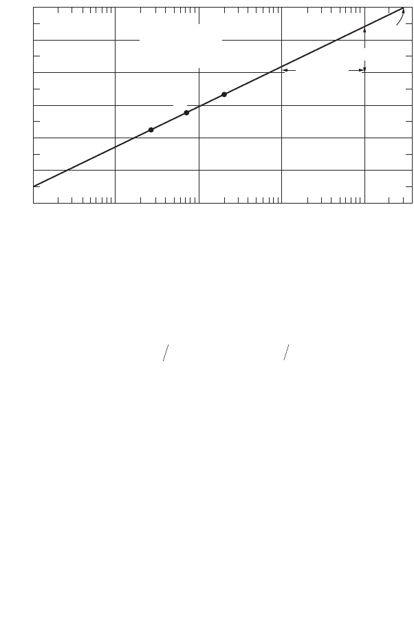
be used. In this latter approach a semi-logarithmic plot of the drawdown (arithmetic scale) vs. the distance
r from the well (logarithmic scale) is used (Fig. 34.4) and the aquifer constants are given by
where Ds = the drawdown across one log cycle of r
t = the time at which the drawdowns were measured
r
o
= the distance intercept of the straight line fitted through the drawdowns at several distances.
Application of the Theis equation and solutions for unconfined aquifers require more elaborate graphic
solutions (Bouwer, 1978; Fetter, 2001; Freeze and Cherry, 1979) or computer solutions (Boonstra, 1989,
Kasenow and Pare, 1996).
The well test can also be performed using only the drawdown measurements at the pumped well
without observation wells. This type of test is called the single well test. The previous equations assume
laminar flow and a linear relationship between drawdown through the geologic formation and discharge.
As the flow reaches the gravel pack around the well screen the velocity increases and the flow becomes
turbulent except for very small pumping rates. The total drawdown at the well s
t
is thus the sum of the
formation drawdown s and the well loss s
w
(Walton, 1962).
where the constant C is related to well characteristics.
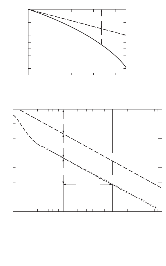
If the well is pumped at different rates for the same length of time, a plot can be prepared of the total
drawdown versus discharge. A tangent at the origin will separate the formation drawdown and the well
loss. The time-drawdown plot is then performed for a constant discharge and the transmissivity is
determined as before. A line is plotted parallel to the straight line portion of the time-drawdown
observations at a distance s
w
above the observations. This line determines the time intercept t
o
used in
the relationship for the storage constant S, (Fig. 34.5). For more details on well hydraulics and well tests
see, for example, Boonstra (1999a).
Multiple Wells and Boundaries
For multiple wells the total drawdown s
t
is the sum of the drawdowns due to the individual wells. For
the case of a confined aquifer the Theis formula yields:
FIGURE 34.4 Distance-drawdown analysis. (Source: Heath, R.C. 1998. Basic Ground-Water Hydrology. U.S. Geolog-
ical Survey, Water Supply Paper 2220, U.S. Government Printing Office.)
0
2
4
6
8
10
12
r
0
C
A
110100 1000 10,000
Distance (in meters)
Drawdown (s), (in meters)
t=4 days
Q=9.3 m
3
/min
r
0
= 30,000 m
∆s = 2.4 m
Log cycle
B
TQsS Ttr=
()
=23 2 225
0
2
. .pD
sss BQCQ
tw
=+ = +
2
© 2003 by CRC Press LLC
Groundwater Engineering 34-9
where u
i
= r
i
2
S/(4 Tt
i
) in which r
i
is the distance from the i th pumping well to the observation point
t
i
= the time since pumping began at well i with a discharge Q
i
In the case of a pumping well and a recharge well, the change in the piezometric surface is the algebraic
sum of the drawdown due to the pumped well and the buildup due to the recharge well. Well interference
is an important matter in the design of well fields.
A recharge boundary or an impervious boundary within the cone of depression modifies the shape
of the drawdown curve. The effect of a perennial stream close to a pumped well can be analyzed by
considering an image recharge well operated at the same flow rate. The drawdown is the algebraic sum
of the drawdowns due to the pumped and the image recharge wells. The resulting water level is constrained
by the water surface elevation in the perennial stream. Similarly the effect of a vertical impervious boundary
near a pumped well can be analyzed by considering an image pumping well operating at the same
FIGURE 34.5 Single well test. (Source: Heath, R.C., 1998. Basic Ground-Water Hydrology. U.S. Geological Survey
Water Supply Paper 2220, U.S. Government Printing Office.)
0.1 1
01 2 34
10
5
0
10 100
Time (in minutes)
7
6
5
4
3
2
1
0
Drawdown (in meters)
Drawdown (in meters)
1 log cycle
Pumping well with well loss
Pumping well with no well loss
∆s
a
s
w
s
a
t
0
s
a
s
w
Total Drawdown, s
t
s
a
= Aquifer loss
s
w
=well loss
Pumping rate
(in cubic meters per minute)
Relation of pumping rate and drawdown
sTQWuQWu
t
=
()
()
+
()
+º
[]
-
4
1
112 2
p
© 2003 by CRC Press LLC
34-10 The Civil Engineering Handbook, Second Edition
discharge. The resulting drawdown is the sum of the drawdowns. The resultant water level is seen to be
perpendicular to the vertical impervious boundary. This horizontal surface has no gradient at the
boundary thus indicating that there is no flow, which is consistent with the requirement of an impervious
boundary. More elaborate boundaries can be simulated by the method of images.
34.3 Well Design and Construction
Well Design
Well design includes the selection of the well diameter, total
depth of the well, screen or open hole sections, gravel pack
thickness and method of construction. The pumping rate
determines the pump size, which in turn determines the well
diameter. Well pump manufacturers provide information on
the optimum well diameter and size of pump bowls for several
anticipated well yields.
Generally water enters a well through a wire screen or a
louvered or shuttered perforated casing. The screen diameter
is selected so that the entrance velocity of the water does not
exceed 0.1 ft/s (0.03m/s). Dividing the design discharge by this
velocity gives the required open area of the screen. A safety
factor of 1.5 to 2.0 is applied to this area to account for the
fact that part of the screen may be blocked by gravel packed
material. The manufacturers supply the open areas of screen
per lineal foot for different slot sizes and screen diameters.
The required length of the screen is obtained by dividing the
required area by the open area per lineal foot. Screens are
normally installed in the middle 70% to 80% of confined
aquifers and the lower 30% to 40% of unconfined aquifers.
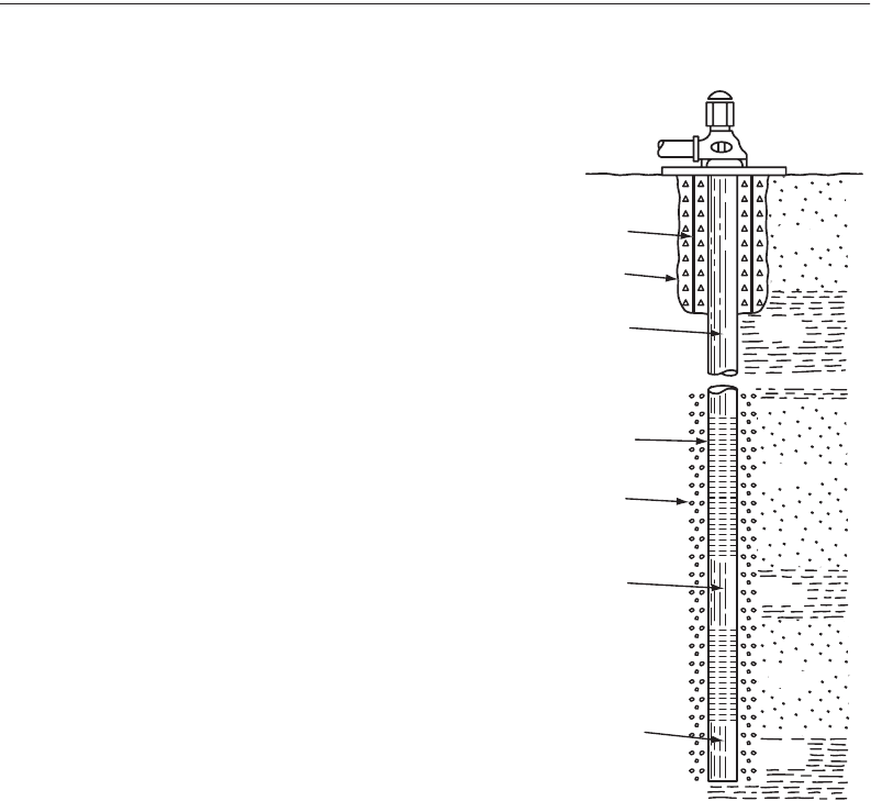
A gravel envelope or gravel pack (Fig. 34.6) is used around
the screen to prevent fine material from entering the well.
Gravel packs make it possible to use larger screen slots thus
reducing the well loss. They also increase the effective radius
of the well. Gravel packs are used in fine textured aquifers in
which D
90
(the sieve size retaining 90% of the material) is less
than 0.25 mm and has a coefficient of uniformity D
40
/D
90
< 3.
Wells dug through multiple layers of sand and clay are generally
constructed with a gravel pack (Fig. 34.6). A sand bridge is
usually provided at the top of the gravel pack to separate it
from the impermeable grout that extends to the surface. The
well casing should extend somewhat higher than the ground
level and a concrete slab sloping away from the well is provided
to prevent surface runoff from entering into the well.
Construction Methods
The principal methods of well construction include digging, boring, driving, jetting, percussion drilling,
hydraulic rotary drilling, and air rotary drilling. Table 34.2 indicates the suitability of the several well
construction methods according to geologic conditions.
After the construction is completed the well is developed, stimulated, and sterilized. The removal of
fine sand and construction mud is called well development. This can be accomplished by water or air
FIGURE 34.6 Supply well with multiple
screen and gravel pack. (Source, Heath, R.C.,
1998. Basic Ground-Water Hydrology. U.S.
Geological Survey Water Supply Paper 2220,
U.S. Government Printing Office.)
Surface
casing
Grout
Steel
casing
Screen
Gravel
pack
Blank
casing
Sediment
trap
Sand
Clay
Clay
Clay
Sand
Sand
© 2003 by CRC Press LLC

Groundwater Engineering 34-11
surging. Stimulation is a technique to increase the well production by loosening consolidated material
around the well. For example, high-pressure liquid can be injected into the well to increase the size of
the fractures in the rock surrounding the well. Finally, water supply wells should be sterilized. This can
be done with chlorine or other disinfectant.
Centrifugal pumps are normally used for water supply wells. If the water level in the well is below the
center line of the pump it is necessary to check that the available positive suction head exceeds the
required positive suction head specified by the manufacturer in order to avoid cavitation. For high heads
multiple stage pumps are used. Submersible pumps avoid the need of long shafts and are used for very
deep wells. Drillers keep well logs or records of the geological formation encountered.
For further details about well drilling methods, well design, well screens, well pumps and their
maintenance the reader is referred to the works of Driscoll (1986) and Boonstra (1999 b).
34.4 Land Subsidence
Introduction
Groundwater pumping causes a downward movement of the water table or of the piezometric surface
which in turn can cause a downward movement of the land surface called subsidence or consolidation.
This movement can be a few centimeters to several meters. If the subsidence is not uniform, the differential
settlement can produce severe damage to structures.
Calculation of Subsidence
Consider a unit area of a horizontal plane at a depth Z below the ground surface. The total downward
pressure P
t
due to the weight of the overburden on the plane is resisted partly by the upward hydrostatic
pressure P
h
and partly by the intergranular pressure P
i
exerted between the grains of the material:
TABLE 34.2 Suitability of Different Well Construction Methods to Geologic Conditions
Drilled
Percussion
Rotary
Characteristics Dug Bored Driven Jetted (cable tool) Hydraulic Air
Maximum practical depth, in m (ft) 15 (50) 30 (100) 15 (50) 30 (100) 300 (1000) 300 (1000) 250 (800)
Range in diameter, in cm (in.) 1–6m
(3–20 ft)
5–75
(2–30)
3–6
(1–2)
5–30
(2–12)
10–46
(4–18)
10–61
(4–24)
10–25
(4–10)
Unconsolidated material:
Silt X X X X X X
Sand X X X X X X
Gravel X X X X
Glacial till X X X X
Shell and limestone X X X X X
Consolidated material:
Cemented gravel X X X X
Sandstone X X X
Limestone X X X
Shale XXX
Igneous and metamorphic rocks X X X
Source: Heath, R.C., 1998. Basic Ground-Water Hydrology.U.S. Geological Survey Water Supply Paper 2220, U.S. Govern-
ment Printing Office.
PPP PPP
thi ith
=+ =- or
© 2003 by CRC Press LLC

34-12 The Civil Engineering Handbook, Second Edition
A lowering of the water table results in a decrease of the hydrostatic pressure and a corresponding
increase in the intergranular pressure. If P
i1
and P
i2
denote the intergranular pressures before and after a
drop in the water table or piezometric surface, the subsidence S
u
can be calculated as
where E is the modulus of elasticity of the soil.
If there are layers of different soil types, the subsidences are calculated for each layer and added to
yield the total subsidence. As the modulus of elasticity of clayey materials is much less than that of sands
and gravel, most of the settlement takes place in the clayey layers.
The previous equation can also be used to calculate the rebound when the intergranular pressure
decreases. Caution must be exercised because the modulus of elasticity usually is not the same for
decompression as for compression. This is particularly the case for clays. For Boston blue clay the rebound
modulus of elasticity is only about 50% of that for compression (Bouwer,1978, p 323). If subsidence has
occurred for a long time, complete rebound is unlikely to occur.
If there is an upward vertical flow, the head loss due to friction as the water flows in the pores results
in an increase in the hydrostatic pressure. This in turn results in a decrease in the intergranular pressure.
A condition known as quicksand is reached when the intergranular pressure vanishes and the sand loses
its bearing capacity. Horizontal flow of the ground water can cause a lateral displacement that can result
in damage to wells.
34.5 Contaminant Transport
Introduction
This section describes the transport and fate of constituents in groundwater. Constituent is a general term
that does not necessarily imply a polluting substance. The fate of a constituent depends on its transport
through the groundwater and includes possible decay or reactions that may occur. The nature, behavior
and physicochemical characteristics of important groundwater contaminants have been described by
Blatchley and Thompson (1999). Contaminant transport can occur by advection, diffusion, and disper-
sion. Transport of solutes can be accompanied by chemical processes such as precipitation, dissolution,
sorption, radioactive decay and biochemical processes such as biodegradation.
Advection
Advection is the movement of a constituent as a result of the flow of the groundwater. It is the most
important mechanism of solute transport. The average flow velocity in the pores v is obtained by dividing
the Darcy or gross velocity by the effective porosity n
e
or v
x
= –[K/n
e
]/(∂h/∂x), where K is the hydraulic
conductivity and ∂h/∂x is the hydraulic gradient. The one-dimensional differential equation for the
advection transport in the x direction is given by:
where C is the solute concentration (M/L
3
).
Diffusion and Dispersion
Diffusion is the spreading of the solute due to molecular activity. The mass flux of solute per unit area
per unit time F is given by Fick’s law; F = –D
d
(∂C/∂x), where C is the solute concentration (M/L
3
) and
D
d
is the diffusion coefficient (L
2
/T). For solutes in an infinite medium this coefficient is of the order of
10
–9
to 2 ¥ 10
–9
m
2
/s at 20∞ C and varies slightly with temperature. The diffusion coefficient in a porous
medium is reduced by a factor of 0.1 to 0.7 for clays and sands, respectively (de Marsily, 1986, p 233)
because of the tortuosity of the flow paths, and is designated by D*. The variability of the pore sizes, the
SZPPE
uii
=-
[]
12
∂∂=- ∂∂Ct v Cx
x

Groundwater Engineering 34-13
multiplicity of flow paths of different lengths and the variation of the velocity distribution in the pores
of different sizes result in a mechanical spreading known as dispersion. The longitudinal dispersion in
the flow direction is larger than the transverse dispersion perpendicular to the flow direction. When
advection and dispersion are the dominant transport mechanisms diffusion is a second order effect.
Molecular diffusion and mechanical dispersion are grouped under the term hydrodynamic disper-
sion. The longitudinal and transverse dispersion coefficients D
L
and D
T
,, respectively, are given by
where a
L
and a
T
= the longitudinal and transverse dynamic dispersivity
D* = the molecular diffusion coefficient in the porous medium
The relative importance of the dynamic dispersivity and the molecular diffusion can be determined
from the value of the Peclet number. It is defined as P
e
= v
x
L/D
d
where L is a characteristic length of the
porous medium, generally taken as the mean diameter of the grains or the pores. The longitudinal
advective dispersion dominates over the molecular diffusion when P
e
> 10 and the transverse advective
dispersion dominates when P
e
> 100. The dispersion coefficients a
L
and a
T
are known to vary with the
scale at which they are measured. Fetter (1999, p 80–86), as a first approximation, suggested the regression
equation a
L
= 0.1 x where x is the flow distance. Other expressions can be found in the literature. For
example, for the dispersivities measured in the field, called apparent dispersivities and designated by a
m
,
Neuman (1990) proposed a
m
= 0.0175L
s
1.46
(both a
m
and L
s
are in meters) for travel distances L
s
less
than 3500 m and Xu and Eckstein (1995) proposed a
m
= 0.83(log L
s
)
2.414
(both a
m
and L
s
are in meters).
This latter equation does not have the distance restriction that the Newman equation has.
The two-dimensional diffusion-dispersion in a flow in the x direction in an homogeneous aquifer is
governed by the equation:
Sorption
This discussion is limited to the cases of adsorption when the solute in the groundwater becomes attached
to the surface of the porous medium and cation exchange when positively charged ions in the solute are
attracted by negatively charged clay particles. The relationships relating the solute concentration C of a
substance to the amount of that substance per unit mass in the solid phase, F, are called isotherms because
they are determined at constant temperature. The simplest is the linear isotherm F = K
d
C where K
d
is
the distribution coefficient. Nonlinear isotherms have been proposed.
The effect of the adsorption is to retard the transport of the substance. The resulting one-dimensional
advection-diffusion-dispersion equation for a flow in the x direction in an homogeneous aquifer is:
where R =1+ K
d
r
b
/n
e
is the retardation factor in which n
e
is the effective porosity
r
b
= the bulk density of the porous medium
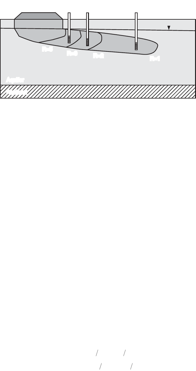
Figure 34.7 shows a chemical spill with several constituents at similar concentrations and different
retardation factors. Constituent 3 with R = 3 has more affinity for the soil matrix than constituents 2 or
1 with R values of 2 or 1, respectively. Thus constituent 3 will spend more time in association with the
soil matrix than constituents 2 or 1. Contaminants with lower retardation factors are transported over
greater distances over a given time period than contaminant with larger retardation factors. As a result,
a monitoring well network has a greater chance of encountering contaminants with low retardation
factors because they occupy a greater volume of the aquifer.
DvD
LLx
=+
*
a
DvD
TTx
=+
*
a .
∂∂= ∂∂+ ∂∂- ∂∂Ct D Cx D Cy v Cx
LTx
22 22
RC t D C x v C x
Lx
∂∂= ∂∂- ∂∂
22
© 2003 by CRC Press LLC
34-14 The Civil Engineering Handbook, Second Edition
In the case of organic compounds the partition coefficient is K
d
= K
oc
f
oc
where K
oc
is the partition
coefficient with respect to organic carbon and f
oc
is the fraction of organic carbon. A number of regression
equations have been obtained that relate K
oc
to the octanol-water partition coefficient and to the aqueous
solubility (de Marsily, 1986, Fetter, 1999).
Multiphase Flow
Liquids that are not miscible with water are called nonaqueous phase liquids (NAPL). In the unsaturated
zone four phases may be present: soil, water, air and NAPL. Many contaminant problems are associated
with the movement of NAPL. The NAPL can have densities that are less than that of water and are called
light nonaqueous phase liquids (LNAPL) or they can have densities that are larger than that of water and
are called dense nonaqueous phase liquids (DNAPL). In an unconfined aquifer a LNAPL will tend to
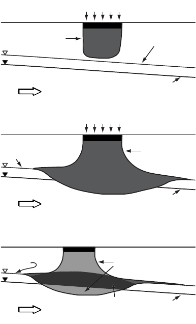
float near the water table whereas a DNAPL will tend to sink to the bottom of the aquifer. Figure 34.8
shows a schematic illustration of the behavior of LNAPL compounds. Under some conditions (a), the
mass of an LNAPL spill is insufficient to allow penetration to the capillary fringe. With additional
compound introduction (b), the LNAPL product will reach the water table and begin to spread, though
the compound will not penetrate far beyond the phreatic surface. If the source of LNAPL is eliminated
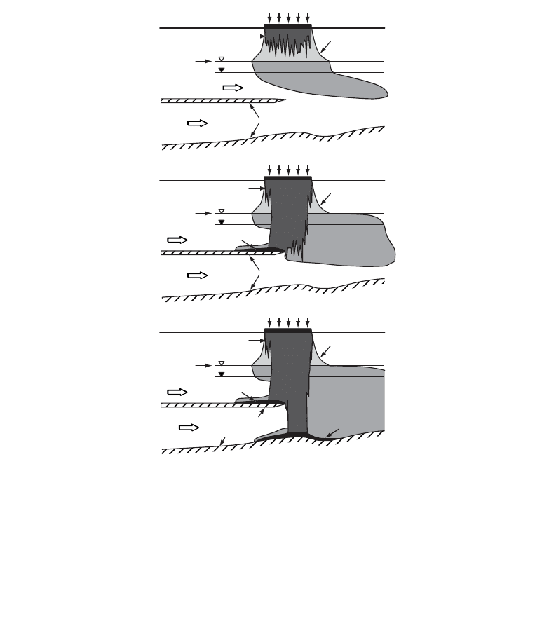
(c), removal of the NAPL will allow “rebound” of the water table. Figure 34.9 shows a schematic illus-
tration of the behavior of DNAPL compounds. Under some conditions (A), the mass of DNAPL spill is
insufficient to allow penetration to the capillary fringe; vertical movement of the DNAPL is by viscous
fingering. With additional compound introduction (B,C), the DNAPL product will reach the water table
and continue to move vertically until it reaches an impermeable boundary.
When two liquids compete for the pore space one will preferentially spread over the grain surface and
wet it. The wettability depends upon the interfacial tension between the two fluids. In the case of oil-
and-water systems, water is the wetting fluid in the saturated zone but in the unsaturated zone oil is the
wetting fluid if the soil is very dry. The relative permeability is the ratio of the permeability of a fluid at
a given saturation to the intrinsic permeability of the rock k
.
. The relative permeability of the wetting
fluid is designated by k
rw
and that of the nonwetting fluid is k
rnw
. For two phase flow Darcy’s laws for the
wetting and nonwetting liquids are respectively
FIGURE 34.7 Transport of contaminants with several retardation factors at a waste site. (Source: U.S. Environmental
protection Agency. 1989. Transport and Fate of Contaminants in the Subsurface, EPA/625/4–89/019.)
Waste
1,2,3
detected
1&2
detected
1 only
detected
R=5
Aquifer
Aquitard
R=3
R=2
R=1
Qkk Ahs
Qkk Ahs
wrwww w
nw rnw nw nw nw
=-
[]
∂∂
=-
[]
∂∂
rm
rm
© 2003 by CRC Press LLC
Groundwater Engineering 34-15
where the subscripts w and nw refer to the wetting and nonwetting fluids, respectively, m is the viscosity
and A
is the cross sectional area of the flow.
If an LNAPL (e.g., oil) is spilled on the ground it will infiltrate, move vertically in the vadose zone
and, if sufficient quantity is available, eventually it will reach the top of the capillary fringe. Some residual
NAPL remains in the vadose zone. As the NAPL (oil) accumulates over the capillary zone an oil table
(oil surface at atmospheric pressure) forms and the water capillary fringe becomes thinner and eventually
completely disappears. The oil table then rests on the water table (Abdul, 1988). The mobile oil below
the oil table moves downward along the slope of the water capillary fringe. Soluble constituents of the
LNAPL are dissolved in the ground water and are transported by advection and diffusion close to the
water table. The residual NAPL left behind in the vadose zone partitions into vapor and liquid phases
depending upon the degree of volatility and of water solubility. The thickness of LNAPL in a monitoring
well is larger than that of free LNAPL in the subsurface.
If a DNAPL (e.g., chlorinated hydrocarbon) spills on the ground surface, under the force of gravity,
it migrates through the vadose zone and through the saturated zone, eventually reaching an impervious
layer. A layer of DNAPL then accumulates over the impervious layer. The mobile DNAPL then migrates
along the slope of the impervious surface, which does not necessarily coincide with the slope of the water
table and the direction of the ground flow. Monitoring wells placed just at the top of the impervious
layer will show the presence of the DNAPL at the bottom of the well. If the well extends into the impervious
FIGURE 34.8 Movement of LNAPL into the subsurface (a) distribution of LNAPL after a small volume has been
spilled; (b) depression of the capillary fringe and water table; (c) rebound of the water table as the LNAPL drains
from overlying pore space. (Source: U.S. Environmental protection Agency. 1989. Transport and Fate of Contaminants
in the Subsurface, EPA/625/4–89/019.)
Product Source
Watertable
Product
Entering
Subsurface
Groundwater
Flow
Top of Capillary
Fringe
Product Source
Watertable
Product
Entering
Subsurface
Groundwater
Flow
Top of
Capillary
Fringe
Product Source
Inactive
Watertable
Product
Product at
Residual
Saturation
Groundwater
Flow
Top of Capillary
Fringe
(a)
(b)
(c)
© 2003 by CRC Press LLC
34-16 The Civil Engineering Handbook, Second Edition
layer the DNAPL will also fill that portion of the monitoring well below the impervious surface that acts
as a sump.
34.6 Remediation
Monitoring Wells
Before any site remediation work is undertaken it is necessary to explore the aquifer and the extent of
the ground water contamination. Monitoring wells are used principally for measuring the elevation of
the water table or of the piezometric level, to collect water samples for chemical analysis and eventually
observe the presence of nonaqueous phase liquids (lighter or denser than water) and to collect samples
of these nonaqueous phase liquids. The equipment and supplies must be decontaminated before they
are used in a water quality monitoring well.
If the purpose of the well is for observation of the water elevation only, a 1-in. casing is adequate. If
water samples are required a 2-in. casing is necessary. Screens are used to allow the water into the well.
In unconfined aquifers the screens must be placed so that they extend approximately from 5 ft. above
the expected high water table to 5 ft below the expected low water table level. Piezometer screens for
confined aquifers are shorter and generally have a length of 2 to 5 ft. The screen is surrounded by a filter
FIGURE 34.9 Movement of DNAPL into the subsurface : distributions of DNAPL after a small (A), moderate (B),
and large (C) volumes have been spilled. (Source: U.S. Environmental Protection Agency. 1989. Transport and Fate
of Contaminants in the Subsurface, EPA/625/4–89/019.)
Groundwater Flow
DNAPL Source
Top of Capillary
Fringe
Watertable
Residual DNAPL
Groundwater
Flow
Dissolved
Chemical Plume
Dense
Vapors
Lower
Permeability
Strata
DNAPL Source
Top of Capillary
Fringe
Watertable
Residual DNAPL
Groundwater
Flow
Dissolved
Chemical Plume
Dense
Vapors
Lower
Permeability Strata
DNAPL Layer
DNAPL Source
Top of Capillary
Fringe
Watertable
Residual DNAPL
Groundwater
Flow
Dissolved
Chemical Plume
Dense
Vapors
Lower
Permeability
Strata
DNAPL Layer
DNAPL Layer
(A)
(B)
(C)
© 2003 by CRC Press LLC

Groundwater Engineering 34-17
pack consisting of medium to coarse silica sand. The filter pack extends about 2 ft above the screen. A
seal is placed on top of the filter pack. It consists of a 2-ft layer of fine sand and an optional 2-ft layer of
granular bentonite for further sealing. If there is a leachate plume several wells with different depths and
screen lengths may be necessary to intercept the plume. Multilevel sampling devices that are installed in
a single casing have been developed.
Monitoring of the water quality in the vadose zone can be accomplished with lysimeters, which are
installed in a bore hole above the water table. The lysimeter consists principally of a porous cup mounted
at the lower end of a tube with a stopper at the upper end. As the soil water pressure is below atmospheric,
suction must be applied so that the water penetrates the porous cup. The water accumulated in the
porous cup is then pumped into a flask at ground level.
For more details on groundwater monitoring, see, for example, Houlihan and Lucia (1999a).
Removal and Containment of Contaminants
Control of the source will prevent the continued addition of pollutant. The three principal methods of
source control are: removal, containment and hydrodynamic isolation. Removal of the source will require
transportation of the waste and its final disposition in an environmentally acceptable manner. Contain-
ment of the waste can generally be accomplished by a cutoff wall made of soil-bentonite slurry or concrete.
The waste can also be isolated hydrodynamically by installing a pumping well immediately downstream
of the contaminant plume so that the flow through the contaminated zone is captured by the well. The
shape of the capture zone with a single well at the origin of the coordinate axes has been given by Javandel
and Tsang (1986) for a confined aquifer as
where Q = the pumping rate
B = the thickness of the aquifer
U = the regional Darcy velocity
Javandel and Tsang (1986) also give equations for the capture zone formed by several wells. Figure 34.10
shows the capture zones for a single well for several values of Q/BU. The curve that fully encloses the
plume is selected. The required pumping rate is obtained by multiplying the value of the parameter Q/BU
by the product of the aquifer thickness, B, and the regional flow velocity, U.
Wellhead Protection
The Wellhead Protection Area is usually delimited as the capture zone of the well or well field limited by
lines of equal travel time or isochrones. For a single well pumped at a rate Q in a confined aquifer of
thickness B and regional Darcy velocity U, the curves of Fig. 34.10 show the capture zones in terms of
the parameter Q/BU. The capture zone can thus be found for given values of Q, U, and B. The capture
zone is an elongated area that extends in the up-gradient direction from a stagnation point located slightly
down-gradient of the pumping well. It is possible to draw the streamlines inside the capture zone and
to mark on them points of equal travel time to the well. The points with equal travel times can be
connected by curves called isochrones. The one to three years isochrones are for short travel time and
5 to 10 years for long travel time. For example, the area from which the groundwater would reach the
well in three years is called the three-year capture zone. In practice computer models are used to delineate
the well head protection areas (see, for example, Haitjema, 1995). After the wellhead protection area is
delineated, the potential sources of contaminant within the area are identified, management approaches
are developed to protect the groundwater within the wellhead protection area and contingency plans are
developed. In the U.S., this type of wellhead protection program is mandated by the Environmental
Protection Agency for the preservation of the quality of groundwater used for production of drinking
water.
yQBUQ BUyx=±
()
-
()
()
-
22
1
p tan
© 2003 by CRC Press LLC