Wai-Fah Chen.The Civil Engineering Handbook
Подождите немного. Документ загружается.


63-12 The Civil Engineering Handbook, Second Edition
(63.4)
The elevations of the vertical curve, y, at horizontal distances, x, from VPC are required for laying out
the vertical curve. If the elevation of VPC is E
VPC
, then y is given by
(63.5)
where y, x, and E
VPC
are in feet. The location of the highest (lowest) point of the curve, x
high
(x
low
), is
important for pavement drainage requirements. The lowest and highest points exist only for vertical
curves of types I and III, respectively (Fig. 63.6). Equating the first derivative of y with respect to x to
zero gives
(63.6)
Chapter 7, Section 7.3 presents more details on the layout of horizontal and vertical curves. The
radius R of the horizontal curve and the parameter K of the vertical curve are determined based on
highway design speed and other parameters, as discussed next.
63.3 Basic Design Applications
The basic elements of geometric design are horizontal alignment, vertical alignment, cross section, and
intersection. The design of these elements involves mainly application of the fundamentals discussed in
the previous section.
Horizontal Alignment
The horizontal alignment consists of straight roadway sections (tangents) connected by horizontal curves,
which are normally circular curves with or without transition (spiral) curves. The basic design features
of horizontal alignment include minimum radius, transition curves, superelevation, and sight distance.
To understand how the minimum radius is determined, the radius–speed relationship is described first.
Radius–Speed Relationship
When a vehicle travels along a horizontal curve, it is forced radially outward by a centrifugal force. The
centrifugal force is counterbalanced by the vehicle weight component related to the roadway superele-
vation and the friction force between the tire and pavement. From the law of mechanics,
(63.7)
where R = the radius of curve (ft)
V = the vehicle speed (mph)
e = the rate of roadway superelevation (in percent)
f = the side friction (demand) factor
The minimum radius is found based on limiting values of e and f.
Maximum Superelevation
The maximum superelevation, e
max
, depends on climatic conditions, terrain, location (urban or rural),
and frequency of slow-moving vehicles. For open highways, the maximum superelevation is 0.10 or 0.12
in areas without snow and ice; otherwise, the maximum superelevation should be 0.08. A rate of 0.12
may also be used for low-volume gravel roads to facilitate cross drainage. A maximum rate of 0.04 or
0.06 is common in urban areas.
K
L
A
=
yE
Gx
x
K
VPC
=+-
1
2
100 200
xKG
high
=
1
R
V
ef
=
+
()
2
15 0 01.
© 2003 by CRC Press LLC
Geometric Design 63-13
Maximum Side Friction
Maximum side friction factors for design are established by AASHTO based on field studies. Table 63.5
shows the recommended design values of f for open highways. The higher side friction factors used for
low-speed urban streets reflect a tolerable degree of discomfort accepted by drivers and provide a margin
of safety compared with actual conditions.
Minimum Radius
For open highways, the minimum radius, R
min
, for a given design speed is calculated from Eq. (63.7)
using the maximum superelevation and maximum side friction factor. When larger radii than R
min
are
used for a given design speed, the required superelevation is found based on a practical distribution of
the superelevation rate over the range of curvature. For rural highways, urban freeways, and high-speed
urban streets, the recommended design superelevation rates for e
max
= 0.04 are shown in Table 63.6.
Similar tables for other e
max
values are given by AASHTO. For low-speed urban streets, an accepted
procedure is to compute the required superelevation rate with f equal to the maximum value. If the
computed value of e is negative, superelevation will not be required (practically, superelevation is set
equal to a minimum of 0.015).
For intersection curves and turning roadways, the minimum radii for various design speeds are shown
in Table 63.7. The values are based on higher side friction factors and minimum rates of superelevation
and are calculated from Eq. (63.7). If conditions allow more than this minimum superelevation, drivers
will drive the curve more comfortably because of less friction or will travel at a higher speed. The following
two examples illustrate the computations of minimum radius and superelevation rate for high-speed and
low-speed urban streets, respectively.
Example 63.2
1. Find the minimum radius on a high-speed urban street with a 50-mph design speed and a 4%
maximum superelevation. From Table 63.5, f = 0.14. From Eq. (63.7), the minimum radius is
The minimum radius can also be obtained from Table 63.6, for V = 50 mph, as 930 ft.
2. Find the required superelevation rate for a flatter curve on the above street with R = 2000 ft. From
Table 63.6, for V = 50 mph, the required superelevation rate is e = 3.2%.
TABLE 63.5 Design Side Friction Factors for Open Highways
Rural Highways, Urban Freeways,
and High-Speed Urban Streets Low-Speed Urban Streets
Design
Speed
(mph)
Side Friction
Factor, f
Design Speed
(mph)
Side Friction
Factor, f
20
30
40
50
60
70
80
0.17
0.16
0.15
0.14
0.12
0.10
0.08
20
25
30
35
40
45
—
0.300
0.252
0.221
0.197
0.178
0.163
—
Source: American Association of State Highway and Transportation
Officials, A Policy on Geometric Design of Highways and Streets, Wash-
ington, D.C., 2001. With permission.
R
min
..
=
()
+
()
=
50
15 0 04 0 14
926
2
ft
© 2003 by CRC Press LLC
63-14 The Civil Engineering Handbook, Second Edition
TA BLE 63.6 Design Elements Related to Horizontal Curvature (e
max
= 0.04)
V
d
= 15 mph V
d
= 20 mph V
d
= 25 mph V
d
= 30 mph V
d
= 35 mph V
d
= 40 mph V
d
= 45 mph V
d
= 50 mph V
d
= 55 mph V
d
= 60 mph
Re24e 24e 24e 24e 24e 24e 24e 24e 24e 24
(ft) (
%) Lns Lns (%) Lns Lns (%) Lns Lns (%) Lns Lns (%) Lns Lns (%) Lns Lns (%) Lns Lns (%) Lns Lns (%) Lns Lns (%) Lns Lns
23000 NC 0 0 NC 0 0 NC 0 0 NC 0 0 NC 0 0 NC 0 0 NC 0 0 NC 0 0 NC 0 0 NC 0 0
20000 NC 0 0 NC 0 0 NC 0 0 NC 0 0 NC 0 0 NC 0 0 NC 0 0 NC 0 0 NC 0 0 NC 0 0
17000 NC 0 0 NC 0 0 NC 0 0 NC 0 0 NC 0 0 NC 0 0 NC 0 0 NC 0 0 NC 0 0 NC 0 0
14000 NC 0 0 NC 0 0 NC 0 0 NC 0 0 NC 0 0 NC 0 0 NC 0 0 NC 0 0 NC 0 0 NC 0 0
12000 NC 0 0 NC 0 0 NC 0 0 NC 0 0 NC 0 0 NC 0 0 NC 0 0 NC 0 0 NC 0 0 NC 0 0
10000 NC 0 0 NC 0 0 NC 0 0 NC 0 0 NC 0 0 NC 0 0 NC 0 0 NC 0 0 NC 0 0 NC 0 0
8000 NC 0 0 NC 0 0 NC 0 0 NC 0 0 NC 0 0 NC 0 0 NC 0 0 NC 0 0 RC 51 77 RC 53 80
6000 NC 0 0 NC 0 0 NC 0 0 NC 0 0 NC 0 0 NC 0 0 NC 0 0 RC 48 72 RC 51 77 2.3 61 92
5000 NC 0 0 NC 0 0 NC 0 0 NC 0 0 NC 0 0 NC 0 0 RC 44 67 RC 48 72 2.3 59 88 2.6 67 100
4000 NC 0 0 NC 0 0 NC 0 0 NC 0 0 NC 0 0 RC 41 62 RC 44 67 2.3 55 83 2.6 66 100 2.8 75 112
3500 NC 0 0 NC 0 0 NC 0 0 NC 0 0 RC 39 58 RC 41 62 2.2 49 73 2.5 60 90 2.7 69 103 3.0 80 120
3000 NC 0 0 NC 0 0 NC 0 0 NC 0 0 RC 39 58 2.1 43 65 2.4 53 80 2.7 65 97 2.9 74 111 3.3 88 132
2500 NC 0 0 NC 0 0 NC 0 0 RC 38 55 RC 39 58 2.4 50 74 2.5 58 87 2.9 70 104 3.2 82 123 3.5 93 140
2000 NC 0 0 NC 0 0 RC 34 51 RC 38 55 2.3 45 67 2.6 54 81 2.9 64 97 3.2 77 115 3.5 89 134 3.8 101 152
1800 NC 0 0 NC 0 0 RC 34 51 2.1 38 57 2.4 46 70 2.7 56 84 3.0 67 100 3.3 79 119 3.7 94 142 3.9 104 156
1600 NC 0 0 NC 0 0 RC 34 51 2.2 40 60 2.6 50 75 2.9 60 90 3.2 71 107 3.5 84 126 3.8 97 146 4.0 107 160
1400 NC 0 0 NC 0 0 RC 34 51 2.4 44 65 2.7 52 78 3.0 62 93 3.4 76 113 3.7 89 133 3.9 100 149 R
min
= 1505
1200 NC 0 0 RC 32 49 2.2 38 57 2.5 45 68 2.9 56 84 3.2 66 99 3.6 80 120 3.9 94 140 4.0 102 153
1000 NC 0 0 RC 32 49 2.4 41 62 2.7 49 74 3.1 60 90 3.5 72 109 3.8 84 127 4.0 96 144 R
min
= 1190
900 NC 0 0 2.1 34 51 2.5 43 64 2.9 53 79 3.2 62 93 3.6 74 112 3.9 87 130 R
min
= 930
800 NC 0 0 2.2 35 54 2.6 45 67 3.0 55 82 3.4 66 99 3.8 79 118 4.0 89 133
700 RC 31 46 2.3 37 56 2.7 46 89 3.2 58 87 3.6 70 105 3.9 81 121 R
min
= 730
600 RC 31 46 2.5 41 61 2.9 50 75 3.4 62 93 3.8 74 110 4.0 83 124
500 2.1 32 48 2.6 42 63 3.1 53 80 3.6 65 98 3.9 75 113 R
min
= 565 e
max
=4%
R =radius of curve
V
d
= assumed design speed
e =rate of superelevation
L = minimum length of runoff (does not include tangent runout)
as discussed in “Tangent-to-Curve transition” section
NC = normal crown section
RC =remove adverse crown, superelevate at normal crown slope
Use of e
max
= 4% should be limited to urban conditions
450 2.2 34 51 2.7 44 66 3.2 55 82 3.7 67 101 4.0 77 116
400 2.3 35 53 2.9 47 71 3.4 58 87 3.8 69 104 R
min
= 420
350 2.4 37 55 3.0 49 73 3.6 62 93 3.9 71 106
300 2.6 40 60 3.2 52 78 3.7 63 95 4.0 73 109
250 2.7 42 62 3.4 55 83 3.9 67 100 R
min
= 300
200 3.0 46 69 3.7 60 90 R
min
= 205
150 3.3 51 76 3.9 63 95
100 3.8 58 88 R
min
= 125
75 4.0 62 92
R
min
= 70
Source: American Association of State Highway and Transportation Officials, A Policy on Geometric Design of Highways and Streets, Washington, D.C., 2001. With permission.
© 2003 by CRC Press LLC
Geometric Design 63-15
Example 63.3
1. Find the minimum radius for a low-speed urban street with a 40-mph design speed and a 6%
maximum superelevation rate. From Table 63.5, f = 0.178, and Eq. (63.7) gives
2. Find the required superelevation rate for a flatter curve on the above street with R = 530 ft. With
f equal to the maximum value, Eq. (63.7) becomes
from which e = 2.4%.
Horizontal Transition Curves
A horizontal transition (spiral) curve is a curve whose radius continuously changes. It provides a tran-
sition between a tangent and a circular curve (simple spiral) or between two circular curves with different
radii (segmental spiral). For simple spirals, the radius varies from infinity at the tangent end to the radius
of the circular curve at the curve end. For segmental spirals, the radius varies from that of the first circular
curve to that of the second circular curve. A transition curve is advantageous because:
1. It provides a natural, smooth path.
2. It provides a length for attaining superelevation.
3. It facilitates pavement widening on curves.
4. It enhances the appearance of the highway.
A practical method for determining the length of a spiral is to use the length required for attaining
superelevation.
Method of Attaining Superelevation
The change in cross slope from a section with an adverse crown removed to a fully superelevated section,
or vice versa, is achieved over a highway length called the superelevation runoff. The runoff depends on
TA BLE 63.7 Minimum Radii for Intersection Curves and Turning Roadways
Design Speed
(mph)
Side Friction
Factor, f
Minimum
Superelevation, e
Minimum Radius (ft)
Computed
Rounded
for Design
10
15
20
25
30
35
40
45
0.38
0.32
0.27
0.23
0.20
0.18
0.16
0.15
0.00
0.00
0.02
0.04
0.06
0.08
0.09
0.10
18
47
92
154
231
314
426
540
25
50
90
150
230
310
430
540
Note: For design speeds of more than 45 mph, use values for open highway
conditions.
Source: American Association of State Highway and Transportation Officials, A
Policy on Geometric Design of Highways and Streets, Washington, D.C., 2001. With
permission.
R
min
..
=
()
+
()
=
()
40
15 0 06 0 178
449 450
2
ft or ft
530
40
15 0 01 0 178
2
=
()
+
()
..e
© 2003 by CRC Press LLC
63-16 The Civil Engineering Handbook, Second Edition
the design speed, superelevation rate, and pavement width. The minimum length of runoff for two-lane
and four-lane highways is obtained from Table 63.6. The superelevation is attained by rotating a crowned
pavement about the centerline, the inside edge, or the outside edge. Figure 63.7 shows the method of
attaining superelevation for a curve to the right when the pavement is rotated about its centerline. For
spiraled circular curves, the length of spiral equals the superelevation runoff. The runoff starts at the
tangent-spiral (TS) point and ends at the spiral-curve (SC) point. For unspiraled circular curves, the
superelevation runoff is typically positioned such that 60 to 80% of the runoff is on the tangent and the
remainder is on the curve. For safety and appearance, angular breaks should be rounded using vertical
curves.
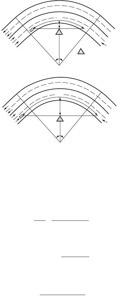
Sight Distance on Horizontal Curves
Sight obstacles such as walls, cut slopes, and buildings on the inside of horizontal curves may restrict
the available sight distance. Figure 63.8 shows the geometry of lateral clearance and SSD on a four-lane
highway. The obstacle lies at the middle of the curve with a lateral clearance measured from the centerline
of the inside lane. The required lateral clearance to satisfy a specified sight distance is computed by [Olson
et al., 1984]
(63.8)
(63.9)
where M = the lateral clearance (ft)
R
n
= the radius to the inside-lane centerline (ft)
S = the sight distance, SSD or PSD (ft)
L = the length of the horizontal curve along the inside-lane centerline (ft)
When the obstacle lies near the ends of the curve, the required lateral clearance needs will be less than
the values computed by Eqs. (63.8) and (63.9). The required lateral clearance for different obstacle
locations have been established [Easa, 1991].
FIGURE 63.7 Attaining superelevation for a curve to the right by rotating pavement about its centerline. (From
AASHTO, A Policy on Geometric Design of Highways and Streets, Washington, D.C., 2001. With permission.)
tangent
runout
length of runoff L
TS
SC
60% 80% L
with spiral
without spiral
outside edge
profile
PC
normal
crown
full
superelevation
inside edge
L
c
MR
S
R
SL
n
n
=-
È
Î
Í
˘
˚
˙
£1
28 65
cos
.
,
M
LSL
R
SL
n
=
-
()
>
2
8
,
© 2003 by CRC Press LLC
Geometric Design 63-17
Example 63.4
A two-lane highway with 12-ft lanes has a horizontal curve designed for an 800-ft radius, a 50-mph
design speed, and I = 40°. Find the required lateral clearance for a middle obstacle to satisfy SSD and
PSD of AASHTO. Since the curve radius is typically given for the highway centerline, R
n
= 800 – 6 =
794 ft. The horizontal curve length is
From Table 63.2, SSD = 425 ft. Since S < L, from Eq. (63.8),
For PSD, from Table 63.2, PSD = 1835 ft. Since S > L, from Eq. (63.9),
The required lateral clearance for PSD is clearly impractical because it would exceed the normal right-
of-way line. Practical design for PSD occurs only for very flat curves.
Vertical Alignment
The vertical alignment consists of straight roadway sections (grades or tangents) connected by vertical
curves. The grade line is laid out in the preliminary location study to reduce the amount of earthwork
and to satisfy other constraints such as minimum and maximum grades. The basic design features of
FIGURE 63.8 Lateral clearance on simple horizontal curve with middle obstacle for SSD: (a) S £ L and (b) S > L.
S
o
o
M
Sight
Line
R
n
I
Obstruction
Inside lane
S
M
Sight
Line
R
n
I
Inside lane
(a)
(b)
L
RI
n
==
¥¥
=
p
180
794 40 3 14
180
554
.
ft
M =-
¥
È
Î
Í
˘
˚
˙
=794 1
28 65 425
794
29cos
.
ft
M =
¥-
()
¥
=
554 2 1835 554
8 794
272 ft
© 2003 by CRC Press LLC
63-18 The Civil Engineering Handbook, Second Edition
vertical alignment include grades, critical length of grade, climbing lanes, emergency escape ramps, and
vertical curve length.
Grades
Maximum grades for different types of roads and design speeds have been established by AASHTO.
Maximum grades of about 5% are considered appropriate for a 70-mph design speed. For a 30-mph
design speed, maximum grades generally range from 7 to 12%, depending on topography. For interme-
diate design speeds, maximum grades lie between the above extremes. For low-volume rural highways,
grades may be 2% steeper. Minimum grades are necessary to facilitate surface drainage. For uncurbed
roads, the grade may be 0%, provided ditch grades are adequate. For curbed roads, the minimum grade
is 0.3%, but a 0.5% grade should be used if possible. For very flat terrain, a grade as low as 0.2% may
be necessary.
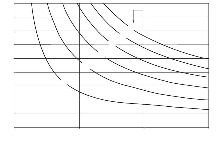
Critical Length of Grade
The critical length of grade is the maximum length of a designated upgrade on which a loaded truck can
operate without an unreasonable reduction in speed. A 10-mph reduction is used as a general guide,
since the accident rate increases significantly when the truck speed reduction is greater than this value.
Figure 63.9 shows the critical length of grade for design for a typical design truck with a weight-to-
horsepower ratio of 200 lb/hp and a 70-mph entering speed. For grades longer than the critical length,
design adjustments to reduce grades or addition of a climbing lane should be considered.
Climbing Lanes
A climbing lane is an extra lane on the upgrade side of a two-lane highway for use by heavy vehicles
whose speeds are significantly reduced on upgrades. Climbing lanes improve traffic operation and safety
and are justified when the following three criteria are satisfied: (1) the upgrade traffic flow rate exceeds
200 vehicles per hour, (2) the upgrade truck volume exceeds 20 vehicles per hour, and (3) one of the
FIGURE 63.9 Critical lengths of grade for design, assumed typical heavy truck of 200 lb/hp, entering speed =
70 mph. (From AASHTO, A Policy on Geometric Design of Highways and Streets, Washington, D.C., 2001. With
permission.)
9
8
7
6
5
4
3
2
1
0
0.0 1000.0 2000.0 3000.0
Length of grade (ft)
Percent upgrade (%)
Speed reduction
5
10
15
20
25
30 mph
© 2003 by CRC Press LLC

Geometric Design 63-19
following conditions exists: a 10-mph or greater speed reduction is expected for a typical heavy truck,
level-of-service E or F exists on the grade, or a reduction of two or more levels of service occurs when
moving from the approach segment to the grade. A climbing lane normally begins where the speed of
the design truck is reduced by 10 mph and ends when the design truck regains a speed equal to that at
the start of the climbing lane. Details on the design of climbing lanes, including entrance and exit
transition tapers, width, signing, and marking, are presented by AASHTO.
Emergency Escape Ramps
An emergency escape ramp is provided on a long, steep downgrade for use by heavy vehicles losing
control because of brake failure (caused by heating or mechanical failure). The ramp allows these vehicles
to decelerate and stop away from the main traffic stream. There are four basic types of emergency escape
ramps: sandpile, descending grade, horizontal grade, and ascending grade. The rolling resistance on the
ramps is supplied by the loose sand or an arresting bed of loose gravel. The ascending grade ramp provides
a force of gravity opposite the vehicle movement, and therefore its length can be shorter than the
descending and horizontal grade ramps. Each ramp type is applicable to a particular topographic situ-
ation. More details on emergency escape ramps can be found in an NCHRP synthesis [Witheford, 1992].
Vertical Curve Length
The length of a vertical parabolic curve, based on Eq. (63.4), is computed by
L = AK (63.10)
where L = the length of vertical curve (ft)
A = the algebraic difference in grades (in percent)
K = the constant
For crest vertical curves, the constant K depends on the sight distance used for design, height of eye
above the roadway surface H
e
, and height of object above the roadway surface H
o
. For sag vertical curves,
the design is generally based on a headlight criterion, and the constant K depends on stopping sight
distance, headlight height H (2 ft), and the upward divergence of the light beam from the longitudinal
axis of the vehicle a (1°). The design (minimum) K values for crest and sag vertical curves are shown in
Table 63.8. These values are computed using the formulas shown in the table, where S equals the sight
distance for crest curves and the SSD for sag curves. The heights H
e
and H
o
are given in Table 63.4. When
the K value needed for design is greater than 167 ft, pavement drainage near the highest (lowest) point,
given by Eq. (63.6), must be more carefully designed. For a small A, the length computed by Eq. (63.10)
may be unrealistically small, and it is common practice to express the minimum curve length (in feet)
as three times the design speed in miles per hour. The use of zero-length and minimum-length vertical
curves has been evaluated by Wooldridge et al. [1999].
A special case is sight distance through a grade separation, where the structure may cut the line of
sight and limit the sight distance. The designer may wish to check the available sight distance at the
underpass to ensure that it satisfies the required sight distance. Such a check may be made graphically,
but equations available in AASHTO can also be used.
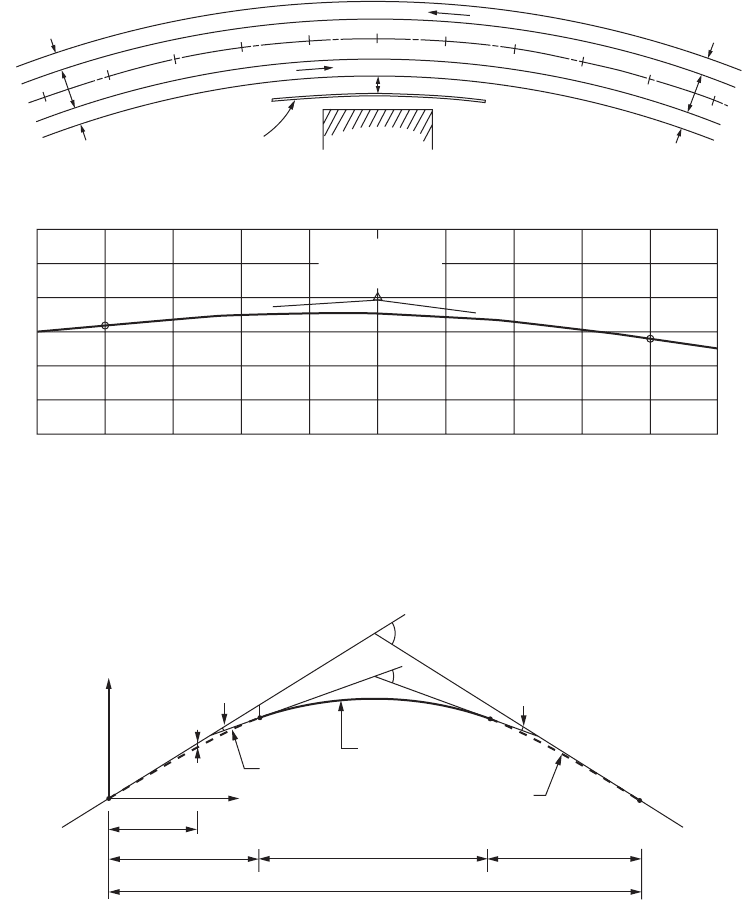
Example 63.5
A section of a four-lane highway with partial access control and a 60-mph design speed lies on a combined
horizontal curve (R = 1432.5 ft) and crest vertical curve (L = 800 ft), as shown in Fig. 63.10. The length
of the horizontal curve is greater than 800 ft. A retaining wall (5 ft high above the pavement) is required
for a planned development near the highway. Determine the adequacy of the design for SSD. To check
sight distance on the vertical curve, from Table 63.8, K = 151. For A = 2.5%, the required length of the
vertical curve, based on Eq. (63.10), is
L minimum ft
()
=¥=25 151 377 5..
© 2003 by CRC Press LLC
63-20 The Civil Engineering Handbook, Second Edition
Since the vertical curve is 800 ft long, sight distance on the vertical curve is adequate. To check sight
distance on the horizontal curve, from Table 63.2, the required SSD is 570 ft. R
n
= 1432.5 – 30 – 18 =
1384.5 ft. From Eq. (63.8) for S £ L, the required lateral clearance is 29.2 ft. Since the distance from the
retaining wall to the inside-lane centerline, given in the design, is 24 + 6 = 30 ft, the minimum sight
distance criterion is also met.
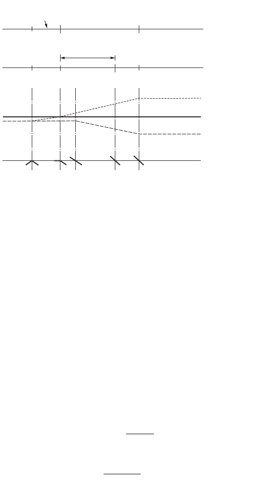
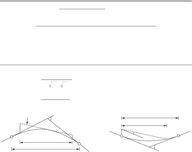
Vertical Transition Curves
Vertical curves are traditionally designed as parabolic curves that are connected directly to the tangents
(without transitions). A vertical transition curve has been recently developed for use before and after a
parabolic curve [Easa and Hassan, 2000]. The resulting vertical curve, called transitioned vertical curve
(Fig. 63.11), consists of transition–parabolic–transition segments. Formulas were developed for the
instantaneous elevation, grade, rate of curvature, offset from the first tangent, and the highest (or lowest)
point on a transitioned crest (or sag) vertical curve, which is important in drainage design. The minimum
length of a transition curve is derived based on the criterion of driver comfort. The transitioned vertical
curve exhibits striking similarities to the spiraled horizontal curve, even though the two curves have
different mathematical functions. Similar to the spiraled horizontal curve, the transitioned vertical curve
is especially useful for sharp vertical alignments.
Cross Section Elements
Typical cross sections for rural highways and urban streets are shown in Fig. 63.12. The cross section
elements include the traveled way, shoulders, curbs, medians, sideslopes and backslopes, clear zones,
TABLE 63.8 Design Rates of Vertical Curvature K for Crest and Sag Vertical Curves
Design
Speed
(mph)
K Va lue for Crest Curves (ft)
K Va lue for Sag Curves (ft)
Stopping
Sight Distance
Stopping
Sight
Distance
Passing
Sight
Distance
20
30
40
50
60
70
80
7
19
44
84
151
247
384
180
424
772
1203
1628
2197
2565
17
37
64
96
136
181
231
For S < L:
For crest curves:
For sag curves:
Source: American Association of State Highway and Transportation Officials, A Policy on Geometric Design of
Highways and Streets, AASHTO, Washington, D.C., 2001. With permission.
K
S
HH
e
=
+
()
2
0
2
200
K
S
HS
=
+µ
()
2
200 tan
Sight line
L
S
A
H
o
H
e
A
L
S
H
a
© 2003 by CRC Press LLC
Geometric Design 63-21
pedestrian facilities, and bicycle facilities. Higher design guidelines for cross section elements are provided
for roads with higher design speeds and volumes.
Traveled Way
The main features of the traveled way are lane width and cross slope. Through-lane width ranges from
10 to 12 ft on most highways, with 12 ft being most common, while auxiliary-lane width ranges from
8 to 12 ft. Auxiliary lanes are used for on-street parking in urban areas; for turning traffic at intersections;
for passing slow vehicles on two-lane highways; and for entering, exiting, and weaving traffic on freeways.
Safety increases with wider lanes up to a width of 12 ft, but greater lane widths do not offer increased
safety. Pavement widening on curves, to provide for vehicle offtracking and additional lateral clearance,
is an important design feature. To facilitate cross drainage, all highways are designed with a normal cross
FIGURE 63.10 Example of sight distance analysis for combined horizontal and vertical curves. (From Jack E. Leisch &
Associates, Notes on Fundamentals of Highway Planning and Geometric Design, Vol. 1, Jack E. Leisch & Associates,
Evanston, IL.)
FIGURE 63.11 Ve rtical transitioned crest curve. (From Easa, S.M. and Hassan, Y., Transp. Res., 34, 481, 2000.)
Building
PLAN
40
24 ft
2 lanes
Retaining wall
2 lanes
24 ft
24 ft
45
60 ft
24 ft
24 ft
60 ft
35
D = 4°
Design speed = 60 mph
open road conditions
630
620
610
35 + 00 40 + 00 45 + 00
LVC = 800 ft
VPI STA 40 + 00
ELEV = 620
+1.00%
1.50%
PROFILE
L
c
Transition
curve
Parabolic
curve
Transition
curve
CS
SC
ST
PVI
PVI
c
TS
X
A
A
c
g
2
rl
/2
g
2
rl
/2
f
l
g
1
+
rl
/2
g
1
f
x
rl
/2
l
L
c
l
L
x
r
Y
© 2003 by CRC Press LLC