Wai-Fah Chen.The Civil Engineering Handbook
Подождите немного. Документ загружается.


12-20 The Civil Engineering Handbook, Second Edition
25 65956 10/3/1980 TGNMO.
53 FR
25 04140 2/12/1988 Revisions to improve method.
53 FR
25 11590 4/7/1988 Correction notice.
48 FR
25A 37595 8/18/1983 TOC/FID.
25B 48 FR 8/18/1983 TOC/NDIR.
37597
61 FR
25C 9929 3/12/1996 VOC from landfills.
59 FR
25D 19311 4/22/1994 VOC from TSDF — purge procedure.
59 FR
25E 62896 12/6/1994 VOC from TSDF — vapor pressure procedure.
56 FR
26 5758 2/13/1991 HCl.
57 FR
26 24550 6/10/1992 Corrections to Method 26.
59 FR
26 19309 4/22/1994 Add 26 HCl, halogens, other hydrogen halides.
59 FR
26A 19309 4/22/1994 Isokinetic HCl, halogens, hydrogen halides.
48 FR
27 37597 8/18/1983 Tank truck leaks.
53 FR
28 05860 2/26/1988 Wood stove certification.
53 FR
28A 05860 2/26/1988 Air to fuel ratio.
61 FR
29 18262 4/25/1996 Multiple metals.
Part 60, Appendix B
62 FR
PS-2-9 P 45639 8/27/1997 Reformat, revise, amend performance specs.
48 FR
PS-1 13322 3/30/1983 Opacity.
59 FR
PS-1 P 60585 11/25/1994 Revisions.
65 FR
PS-1 48914 8/10/2000 Revisions, final rule.
48 FR
PS-2 23608 5/25/1983 SO
2
and NO
x
.
55 FR
PS 1-5 47471 11/14/1991 Technical amendments.
48 FR
PS-3 23608 5/25/1983 CO
2
and O
2
.
50 FR
PS-4 31700 8/5/1985 CO.
56 FR
PS-4A 5526 2/11/1991 CO for MWC.
61 FR
PS-4B P 17495 4/19/1996 CO and O2 for HWI (BIF rules).
PS-4B 64 FR 9/30/1999 Final rule.
53032
48 FR
TA BLE 12.7 (continued) Summary of U.S. EPA Emission Test Methods
Method Status
a
Reference Date Description
© 2003 by CRC Press LLC

Air Pollution 12-21
PS-5 32984 7/20/1983 TRS.
53 FR
PS-6 07514 3/9/1988 Velocity and mass emission rate.
55 FR
PS-7 40171 10/2/1990 H
2
S.
59 FR
PS-8 64580 12/15/1994 VOC CEMS performance specifications.
61 FR
PS-8A P 17495 4/19/1996 VOC CEMS for HWI (BIF rules).
64 FR
PS-8A 53033 9/30/1999 Final rule.
59 FR
PS-9 64580 12/15/1994 GC CEMS performance specifications.
61 FR
PS-10A P 17495 4/19/1996 Metals CEMS.
PS-11 Tentative PM CEMS.
61 FR
PS-11A P 17495 4/19/1996 PM CEMS (BIF MACT).
PS-12 Tentative Hg CEMS.
61 FR
PS-12A P 17495 4/19/1996 Hg CEMS (BIF MACT).
PS-13 Tentative HCl CEMS.
61 FR
PS-13A P 17495 4/19/1996 HCl CEMS (BIF MACT).
PS-14 Tentative Cl CEMS.
61 FR
PS-14A 17495 4/19/1996 Cl CEMS (BIF MACT).
62 FR
PS-15 P 45372 8/27/1997 FTIR CEMS.
Part 60, Appendix F
52 FR
Prc 1 21003 6/4/1987 Quality assurance for CEMS.
56 FR
Prc1 5527 2/11/1991 Revisions.
Part 60, Appendix J
55 FR
App-J 33925 8/20/1990 Wood stove thermal efficiency.
Alternative Procedures and Miscellaneous
48 FR
44700 9/29/1983 S-Factor method for sulfuric acid plants.
48 FR
48669 10/20/1983 Corrections to S-Factor publication.
49 FR
30672 7/31/1984 Add fuel analysis procedures for gas turbines.
51 FR
21762 6/16/1986 Alternative PST for low level concentrations.
54 FR
46234 11/2/1989 Misc. revisions to Appendix A, 40 CFR Part 60.
55 FR
40171 10/2/1990 Monitoring revisions to Subpart J (Petr. Ref.).
54 FR
06660 2/14/1989 Test methods & procedures rev. (40 CFR 60).
TA BLE 12.7 (continued) Summary of U.S. EPA Emission Test Methods
Method Status
a
Reference Date Description
© 2003 by CRC Press LLC

12-22 The Civil Engineering Handbook, Second Edition
54 FR
21344 5/17/1989 Correction notice.
54 FR
27015 6/27/1989 Correction notice.
Part 61, Appendix B
62 FR
101-111 P 45639 8/27/1997 Reformat, revise, amend methods.
47 FR
101 24703 6/8/1982 Hg in air streams.
47 FR
101A 24703 6/8/1982 Hg in sewage sludge incinerators.
61 FR
101A 18262 4/25/1996 Revisions — Consistency with Method 29.
49 FR
101 35768 9/12/1984 Corrections to M-101 and 101A.
47 FR
102 24703 6/8/1982 Hg in H
2
streams.
48 FR
103 55266 12/9/1983 Revised Be screening method.
48 FR
104 55268 12/9/1983 Revised beryllium method.
48 FR
105 48299 10/14/1975 Hg in sewage sludge.
49 FR
105 35768 9/12/1984 Revised Hg in sewage sludge.
47 FR
106 39168 9/7/1982 Vinyl chloride.
47 FR
107 39168 9/7/1982 VC in process streams.
52 FR
107 20397 6/1/1987 Alternative calibration procedure.
47 FR
107A 39485 9/8/1982 VC in process streams.
108 51 FR 8/4/1986 Inorganic arsenic.
28035
51 FR
108A 28035 8/4/1986 Arsenic in ore samples.
51 FR
108B 22026 5/31/1990 Arsenic in ore alternative.
55 FR
108C 22026 5/31/1990 Arsenic in ore alternative.
55 FR
108B/C 32913 8/13/1990 Correction notice.
50 FR
111 05197 2/6/1985 Polonium-210.
54 FR
114 51695 12/15/1989 Monitoring of radio nuclides.
54 FR
115 51702 12/15/1989 Radon-22.
Part 61
53 FR
36972 9/23/1988 Corrections.
Part 51, Appendix M
55 FR
201 14246 4/17/1990 PM-10 (EGR procedure).
TA BLE 12.7 (continued) Summary of U.S. EPA Emission Test Methods
Method Status
a
Reference Date Description
© 2003 by CRC Press LLC

Air Pollution 12-23
55 FR
201A 14246 4/17/1990 PM-10 (CSR procedure).
55 FR
201A 24687 6/18/1990 Correction of equations.
55 FR
201 37606 9/12/1990 Correction of equations.
56 FR
202 65433 12/17/1991 Condensible PM.
57 FR
203 P 46114 10/7/1992 Transmissometer for compliance.
58 FR
203A P 61640 11/22/1993 Visible Emissions — 2-6 min avg.
58 FR
203B P 61640 11/22/1993 Visible Emissions — time exceptions.
58 FR
203C P 61640 11/22/1993 Visible Emissions — instantaneous.
62 FR
204 32500 6/16/1997 VOC Capture Efficiency.
62 FR
204A 32500 6.16.1997 VOC Capture Efficiency.
62 FR
204B 32500 6/16/1997 VOC Capture Efficiency.
62 FR
204C 32500 6/16/1997 VOC Capture Efficiency.
62 FR
204D 32500 6/16/1997 VOC Capture Efficiency.
62 FR
204E 32500 6/16/1997 VOC Capture Efficiency.
62 FR
204F 32500 6/16/1997 VOC Capture Efficiency.
59 FR
205 19590 5/30/1994 Dilution calibration verification.
206 Tentative Ammonia (NH
3
).
62 FR
207 P 64532 12/8/1997 Isocyanates.
Part 63, Appendix A
62 FR
303-306 P 45639 8/27/1997 Reformat, revise, amend methods.
57 FR
301 61970 12/29/1992 Field data validation protocol.
302 (Reserved)
58 FR
303 57898 10/27/1993 Coke Oven Door Emissions.
62 FR
304A 2793 1/17/1997 Biodegradation rate (vented).
62 FR
304B 2793 1/17/1997 Biodegradation rate (enclosed).
59 FR
305 19590 4/22/1994 Compound specific liquid waste.
60 FR
306 4948 1/25/1995 Chromium from electroplaters/anodizers.
60 FR
306A 4948 1/25/1995 Simplified Chromium sampling.
60 FR
306B 4948 1/25/1995 Surface tension of chromium suppressors.
59 FR
TA BLE 12.7 (continued) Summary of U.S. EPA Emission Test Methods
Method Status
a
Reference Date Description
© 2003 by CRC Press LLC

12-24 The Civil Engineering Handbook, Second Edition
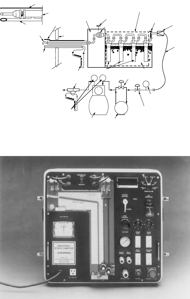
After being drawn through the sample case, the gas stream passes through the umbilical cord to the
control case. In Fig. 12.1, the control case flow path is shown, while Fig. 12.2 is a photograph of a typical
control case. A vacuum gauge indicates negative pressure in the line downstream of the filter. To control
flow to the pump, two valves are used. The first valve is the coarse control valve, and is plumbed
immediately upstream in line with the pump. A second valve, or the fine control valve, controls a recycle
stream around the pump. These valves serve to control the amount of gas sample being drawn by the
system. After the pump, the gas stream passes through a dry gas meter and then through an orifice plate.
The system described above allows a known volume of gas to be drawn with known velocities in the
nozzle. This is important because the velocity of the gas in the ductwork and the velocity of the sample
being drawn by the system can be matched. As a result, particulate in the gas stream can be sampled in
the gas stream or isokinetically. If the sample is collected such that the velocity in the nozzle is greater
than in the duct, the sample is said to be superisokinetic and provides a particulate sample biased on
the low side with regard to mass. A nozzle velocity below the duct velocity is said to be subisokinetic and
307 61801 12/2/1994 Solvent Degreaser VOC.
58 FR
308 P 66079 12/17/1993 Methanol.
309 P 6/6/1994 Aerospace solvent recovery material balance.
62 FR
310A 12546 3/17/1997 Residual hexane in EPDM rubber.
62 FR
310B 12546 3/17/1997 Residual hexane in EPDM rubber.
62 FR
310C 12546 3/17/1997 Residual hexane in EPDM rubber.
60 FR
311 62930 12/7/1995 VOC HAPS in furniture coatings.
312A 62 FR 3/17/1997 Residual styrene in SBR rubber.
12546
62 FR
312B 12546 3/17/1997 Residual styrene in SBR rubber.
62 FR
312C 12546 3/17/1997 Residual styrene in SBR rubber.
62 FR
313A 12546 3/17/1997 Residual styrene in PBR rubber.
62 FR
313B 12546 3/17/1997 Residual styrene in PBR rubber.
314 Tentative Halogentated compounds in solvents.
62 FR
315 52418 10/7/1997 MeCl extractable organic matter.
62 FR
316 P 15257 3/31/1997 Formaldehyde — manual method.
317 Tentative Phenol — manual method.
62 FR
318 P 52266 3/31/1997 Formaldehyde, phenol, methanol with FTIR.
61 FR
319 P 55862 10/29/1996 Filter efficiency, paint over-spray.
64 FR
320 31898 6/14/1999 Extractive FTIR.
64 FR
321 31898 6/14/1999 FTIR for HCl from Portland cement kilns.
322 Tentative GFC/IR for HCl from Portland cement kilns.
a
Unless designated by “P”, method has been promulgated. “P” implies the method is a proposal.
Te ntative implies the method is under evaluation.
Source: U.S. EPA, Office of Air Quality Planning and Standards.
TA BLE 12.7 (continued) Summary of U.S. EPA Emission Test Methods
Method Status
a
Reference Date Description
© 2003 by CRC Press LLC
Air Pollution 12-25
FIGURE 12.1 Method 5 sampling hardware schematic.
FIGURE 12.2. Typical control case.
TEMPERATURE SENSOR
PITOT TUBE
TEMPERATURE
SENSOR
STACK
WALL
REVERSE-TYPE
PITOT TUBE
PITOT MANOMETER
ORIFICE
THERMOMETERS
DRY GAS METER
AIR-TIGHT
PUMP
MAIN VALVE
VACUUM
GAUGE
BY-PASS VALVE
IMPINGERS ICE BATH
VACUUM
LINE
CHECK
VALVE
THERMOMETER
FILTER HOLDER
THERMOMETER
HEATED AREA
IMPINGER TRAIN OPTIONAL, MAY BE REPLACED
BY AN EQUIVALENT CONDENSER
PROBE
PROBE
© 2003 by CRC Press LLC

12-26 The Civil Engineering Handbook, Second Edition
provides a particulate sample biased on the high side with regard to mass. Thus, to provide an accurate
depiction of the particulate emissions the sample needs to be isokinetic. To this end, the EPA specifies
that the sample be between 90 and 110% isokinetic.
With known stack gas parameters of temperature, pressure, composition, and moisture content, values
for the pressure drop across the orifice in the control case under a different temperature and pressure
can be determined. Thus, with changing duct velocities, different standard flows in the system necessary
to maintain appropriate nozzle velocities can be determined from the calibration graphs for the control
case. As mentioned previously, standard flows are then used to determine the appropriate DH (pressure
drop across the orifice meter) value for a specific velocity pressure. The method 5 sampling train is unique
in that both a rate meter (orifice plate) and totalizing meter (dry gas meter) allow for a post-test check
of the isokinetic percentage.
12.5 Emissions Control
Particulates
Aerodynamic Diameter
Engineers who are concerned with the removal of solid particles from gas streams are less concerned
with the physical shape of the particle and more interested in the particles’ aerodynamic behavior in the
gas stream. As such, the term aerodynamic diameter is widely used in the design and selection of air
pollution control hardware for particulate control. Aerodynamic diameter can be defined as an equivalent
diameter of a nonspherical particle whose actual shape can be spherical but is usually nonspherical and
whose aerodynamic behavior is identical to a unit density sphere in stokes flow.
The measurement of aerodynamic diameter is best performed using isokinetic sampling procedures
directly in the gas stream with a multistage impactor which has been calibrated with unit density spheres.
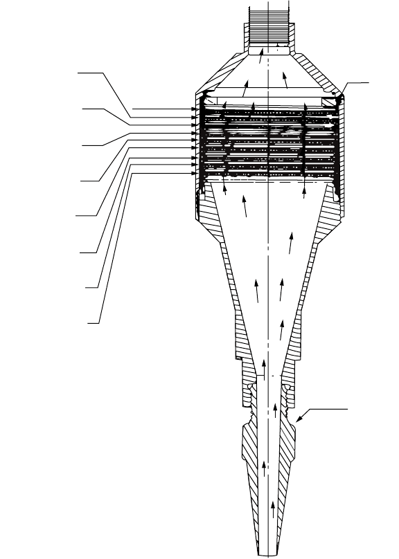
One such impactor is the Anderson® Impactor seen in Fig. 12.3. As the particles proceed through the
multistage impactor, their velocities are stepwise increased at each impaction stage. Immediately following
this acceleration, the conveying gas stream is routed through 90 degree turns at each stage of the impactor.
Since the particles have much greater inertia than the gas molecules, the particles cannot negotiate the
90 degree turns; that is, they deviate from the streamlines of gas flow and impact a collection surface or
stage.
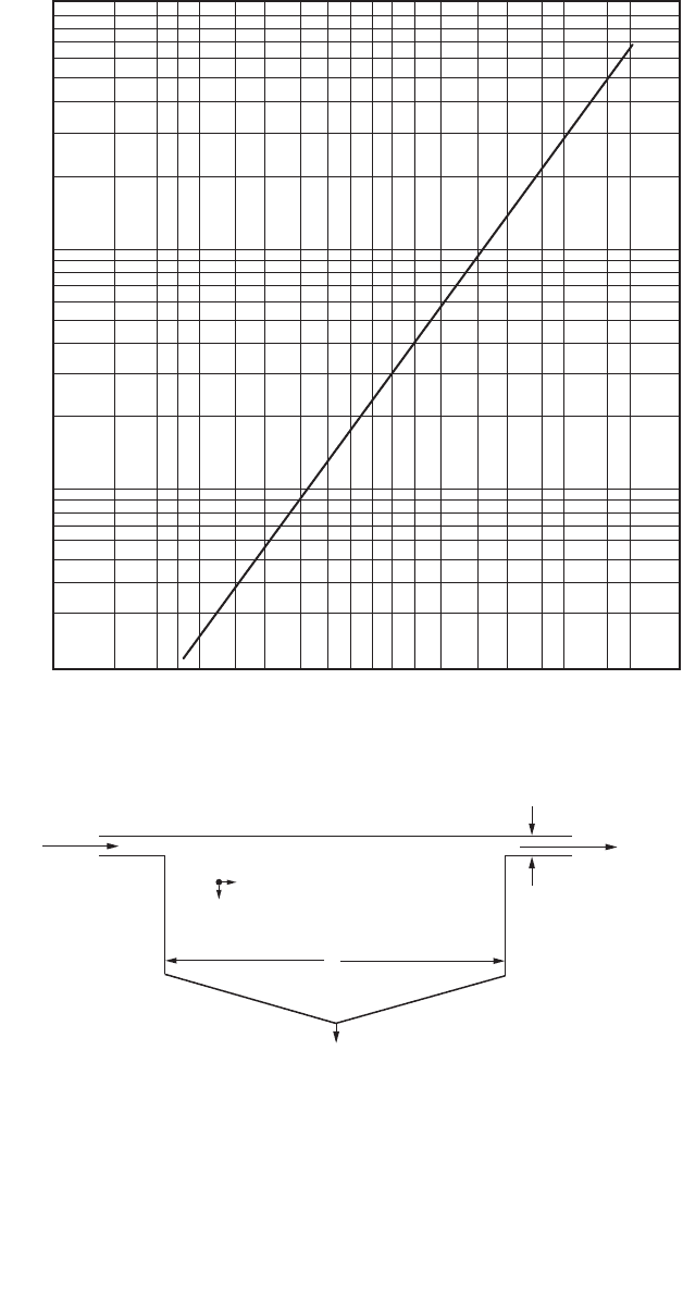
Each collection stage is gravimetrically analyzed and the data is presented graphically on a log-
probability plot seen in Fig. 12.4. Most particulates generated by abrasion, fracturing, or condensation
phenomena have aerodynamic diameters that are log-normally distributed as is reflected by the straight
line shown in Fig. 12.4. This plot is very useful to the engineer either designing or selecting the appropriate
control hardware. For example, particles with an extremely wide aerodynamic diameter distribution
would be represented by an almost vertical line or an infinite slope in Fig. 12.4. On the other hand,
particles which did not vary widely in their aerodynamic diameters would be represented by an almost
horizontal line or a line with near-zero slope. Therefore, a quick glance at the slope immediately tells the
engineer whether he or she is dealing with an almost infinite variability in particle sizes or a near mono-
dispersion of particles.
Additionally, the intersection of the line in Fig. 12.4 with the 50% probability value on the abscissa is
the mass median diameter of the particle distribution. This mass median diameter immediately tells the
engineer what type of particulate control hardware probably will be needed. For example, particle
diameter distributions having submicron mass median diameters require relatively high-energy devices
for removal while super-micron-diameter particles require lesser amounts of energy.
Typically, for particles larger than 40 microns in aerodynamic diameter, gravity force is utilized for
removal. Obviously this force is very cost-effective and if properly combined with low transport velocities
and subsequently high residence times respectable removal efficiencies can result.
© 2003 by CRC Press LLC
Air Pollution 12-27
As the particles become smaller, greater forces must be brought into play for their removal. For particles
between 10 to 40 microns in aerodynamic diameter, centrifugal forces are brought into play through the
use of cyclones. For the removal of particles smaller than 10 microns in aerodynamic diameter, fabric
filtration, electrostatic precipitators, and high-energy wet scrubbing are employed.
Settling Chambers
Particles larger than 40 microns in aerodynamic diameter settle readily under the influence of gravity. If
the particulate matter is being carried in an exhaust gas stream as opposed to fugitive dust in the
atmosphere, a settling chamber is a very cost-effective device for their removal. A settling chamber is
essentially a wide spot in a duct which significantly reduces the gas velocity and, therefore, the particulate
transport velocity, allowing enough residence time for gravity to act on the particle and separate it from
the gas stream.
A side view of a settling chamber is seen in Fig. 12.5. As the entering particle decelerates due to the
increased cross-sectional area for flow, gravity force accelerates the particle to its terminal settling velocity.
FIGURE 12.3 Anderson® impactor.
8
7
6
5
4
3
2
1
0
GASKET
(TYP)
NOZZLE
STAGE
NO.
JET SIZE
JET VELOCITY @
3
/
4
CFM
.0100" Dia.
154 FT/SEC
.0100" Dia.
77.0 FT/SEC
.0135" Dia.
42.3 FT/SEC
.0210" Dia.
17.50 FT/SEC
.0280" Dia.
9.81 FT/SEC
.0360" Dia.
5.91 FT/SEC
.045" Dia.
3.57 FT/SEC
.0636" Dia.
1.91 FT/SEC
AIR FLOW
© 2003 by CRC Press LLC
12-28 The Civil Engineering Handbook, Second Edition
If the residence time in the chamber is sufficient such that the particle falls at least a distance h, the
particle will be captured in the chamber. In other words, for 100% capture, a particle’s fallout time must
be at least be equal to or less than its transport time (residence time):
(12.10)
FIGURE 12.4 Log probability plot.
FIGURE 12.5 Settling chamber.
Particle Size, Microns
10.0
100.0
1.0
Cumulative % Less Than Stated Size
50001 01 05 1 2 5 10 20 30 40 60 70 80 90 95 98 99 99.8 99.9 99.99
Gas
Inlet
L
Particulate Removal
h
Gas
Outlet
V
transport
V
fallout
TT
ft
=
© 2003 by CRC Press LLC
Air Pollution 12-29
If particle fallout time is expressed as
(12.11)
and the particle transport time is expressed as
(12.12)
the relationship for 100% particle capture efficiency is
(12.13)
where T
f
is particle fallout time, T
t
is particle transport time, h is vertical distance the particle must fall
in order to be captured or the distance from the chamber ceiling to the lower lip of the outlet duct, L is
chamber length, and V is the particle’s horizontal transport velocity, which can be assumed to be the
same as the gas velocity.
Therefore, geometric combinations which satisfy the relationship h/V
t
= L/V will successfully capture
particles greater than 40 microns in diameter provided chamber turbulence is small. A reasonable rule
of thumb assumes the terminal settling velocity is one-half of the calculated value and thereby a conser-
vative design is achieved.
Particle Settling Velocity
The terminal settling velocity can be approximated from the following equations according to the particle
diameter and expected flow regime. For particles with aerodynamic diameters less than 100 microns
whose Reynolds numbers are less than about 2.0, the terminal settling velocity, V
t
, is given by the
following:
(12.14)
Equation (12.14) is the terminal settling velocity of a spherical particle in stokes or laminar flow.
For larger particles between 100 and 1000 microns which are in the transition region between laminar
and turbulent flow and whose Reynolds numbers are between about 2.0 and 500, V
t
is given by the
following relationship:
(12.15)
For particles larger than 1000 microns which are in turbulent flow regime and whose Reynolds numbers
are between 500 and 10
5
, V
t
is given by the following:
(12.16)
where V
t
is particle settling velocity, cm/s; r
p
is particle density, g/m
3
; g is acceleration due to gravity,
cm/s
2
; d
p
is particle diameter, cm; and m
f
is fluid viscosity, g/cm-s.
T
h
V
f
t
=
T
L
V
t
=
h
V
L
V
t
=
V
dg
t
ppf
f
=
-
()
2
18
rr
m
V
gd
f
t
pp
f
=
02
23 23
13 13
. r
rm
V
gd
t
pp
f
=
Ê
Ë
Á
ˆ
¯
˜
174
12
.
r
r
© 2003 by CRC Press LLC