Wai-Fah Chen.The Civil Engineering Handbook
Подождите немного. Документ загружается.


23-10 The Civil Engineering Handbook, Second Edition
where = average degree of consolidation
S
t
= settlement at time t
S
f
= final settlement at full consolidation
= average pore pressure at time t
= initial average pore pressure (on application of the load; time t = 0)
Notice that the pore pressure varies throughout the soil layer and Eq. (23.21) assumes average values.
In contrast, the settlement values are not the average, but the accumulated values.
The time for achieving certain degree consolidation is then, as follows:
(23.22)
where t = time to obtain a certain degree of consolidation
T
v
= a dimensionless time coefficient
c
v
= coefficient of consolidation
H = length of the longest drainage path
The time coefficient, T
v
, is a function of the type of pore pressure distribution. Of course, the shape
of the distribution affects the average pore pressure values and a parabolic shape is usually assumed. The
coefficient of consolidation is determined in the laboratory oedometer test (some in situ tests can also
provide c
v
values) and it can rarely be obtained more accurately than within a ratio range of 2 or 3. The
length of the longest drainage path, H, for a soil layer that drains at both surface boundaries is half the
layer thickness. If drainage only occurs at one boundary, H is equal to the full layer thickness. Naturally,
in layered soils, the value of H is difficult to ascertain.
Approximate values of T
v
for different degrees of consolidation are given below. For more exact values
and values to use when the pore pressure distribution is different, see, for example, Holtz and Kovacs
[1981].
In partially saturated soils, consolidation determined from observed settlement is initially seemingly
rapid, because gas (air) will readily compress when subjected to an increase of pressure. This settlement
is often mistaken for the initial compression of the grain solids. However, because the pore pressure will
not diminish to a similar degree, initial consolidation determined from observed pore pressures will not
appear to be as large. In these soils and in seemingly saturated soils that have a high organic content, gas
is present as bubbles in the pore water, and the bubbles will compress readily. Moreover, some of the gas
may go into solution in the water as a consequence of the pressure increase. Inorganic soils below the
groundwater surface are usually saturated and contain no gas. In contrast, organic soils will invariably
contain gas in the form of small bubbles (as well as gas dissolved in the water, which becomes free gas
on release of confining pressure when sampling the soil) and these soils will appear to have a fast initial
consolidation. Toward the end of the consolidation process, when the pore pressure has diminished, the
bubbles will return to the original size and the consolidation process will appear to have slowed.
Generally, the determination
—
prediction
—
of the time for a settlement to develop is filled with
uncertainty and it is very difficult to reliably estimate the amount of settlement occurring within a specific
time after the load application. The prediction is not any easier when one has to consider the development
during the build-up of the load. For details on the subject, see Ladd [1991].
The rather long consolidation time in clay soils can be shortened considerably by means of vertical
drains. Vertical drains installed at spacings ranging from about 1.2 m through 2.0 m have been very
successful in accelerating consolidation from years to months. In the past, vertical drains consisted of
sand drains and installation disturbance in some soils often made the drains cause more problems than
U(%) 25 50 70 80 90 100
T
v
0.05 0.20 0.30 0.40 0.60 1.00
U
u
t
u
0
tT
v
H
2
c
v
------
=
© 2003 by CRC Press LLC

Foundations 23-11
they solved. However, the sand drain is now replaced by premanufactured band-shaped drains, wick
drains, which do not share the difficulties and adverse behavior of sand drains.
Theoretically, when vertical drains have been installed, the drainage is in the horizontal direction and
design formulas have been developed as based on radial drainage. However, vertical drains connect
horizontal layers of greater permeability, which frequently are interspersed in natural soils, which make
the theoretical calculations quite uncertain. Some practical aspects of the use of vertical drains are
described in the CFEM [Canadian Geotechnical Society, 1985].
The settlement will continue after the end of the consolidation. This type of settlement is called creep
or secondary compression. Creep is a function of a coefficient of secondary compression, C
a
, and the ratio
of the time considered after full consolidation and the time for full consolidation to develop:
(23.23)
where C
a
= coefficient of secondary compression
t
a
= time after end of consolidation
t
100
= time for achieving primary compression
In most soils, creep is small in relation to the consolidation settlement and is therefore neglected.
However, in organic soils, creep may be substantial.
Magnitude of Acceptable Settlement
For many years, settlement analysis was limited to ascertaining that the expected settlement should not
exceed one inch. (Realizing that 25.4 mm is too precise a value — as is 25 mm when transferring this
limit to the SI system — some have argued whether the “metric inch” should be 20 mm or 30 mm).
Furthermore, both total settlement and differential settlement must be evaluated. The Canadian Foun-
dation Engineering Manual [Canadian Geotechnical Society, 1985] lists allowable displacement criteria
in terms of maximum deflection between point supports, maximum slope of continuous structures, and
rotation limits for structures. The multitude of limits demonstrate clearly that the acceptable settlement
varies with the type and size of structure considered. Moreover, modern structures often have small
tolerance for settlement and, therefore, require a more thorough settlement analysis. The advent of the
computer and development of sophisticated yet simple to use design software have enabled the structural
engineers to be very precise in the analysis of deformations and the effect of deformations on the stress
and strain in various parts of a structure. As a not so surprising consequence, requests for “settlement-
free” foundations have increased. When the geotechnical engineer is vague on the predicted settlement,
the structural designer “plays it safe” and increases the size of footings or changes the foundation type,
which may increase the costs of the structure. These days, in fact, the geotechnical engineer cannot just
estimate a “less than one inch” value, but must provide a more accurate value by performing a thorough
analysis considering soil compressibility, soil layering, and load variations. Moreover, the analysis must
be put into the context of the structure, which necessitates a continuous communication between the
geotechnical and structural engineers during the design effort. Building codes have started to recognize
the complexity of the problem and mandate that the designers collaborate continuously. See, for example,
the 1993 Canadian Highway Bridge Design Code.
23.3 Bearing Capacity of Shallow Foundations
When society started building and imposing large concentrated loads onto the soil, occasionally the
structure would fail catastrophically. Initially, the understanding of foundation behavior progressed from
one failure to the next. Later, tests were run of model footings in different soils and the test results were
extrapolated to the behavior of full-scale foundations. For example, loading tests on model size footings
e
creep
C
a
1 e
0
+()
------------------
ln
t
a
t
100
-------
=
© 2003 by CRC Press LLC
23-12 The Civil Engineering Handbook, Second Edition
in normally consolidated clay showed load-movement curves where the load increased to a distinct peak
value — bearing capacity failure — indicating that the capacity (not the settlement) of a footing in clay
is independent of the footing size.
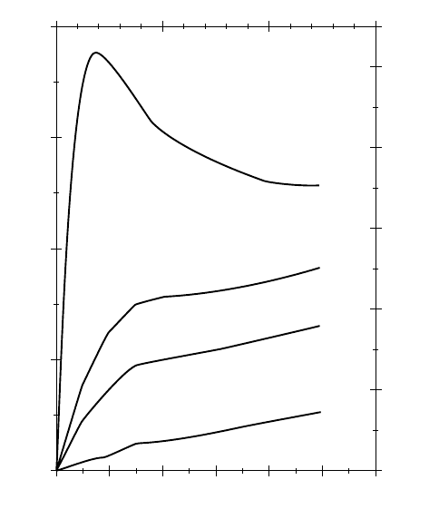
The behavior of footing in clay differs from the behavior of footings in sand, however. Figure 23.1
presents results from loading tests on a 150-mm diameter footing in dry sand of densities varying from
very dense to loose. In the dense sand, a peak value is evident. In less dense sands, no such peak is found.
The capacity and the load movement of a footing in sand are almost directly proportional to the footing
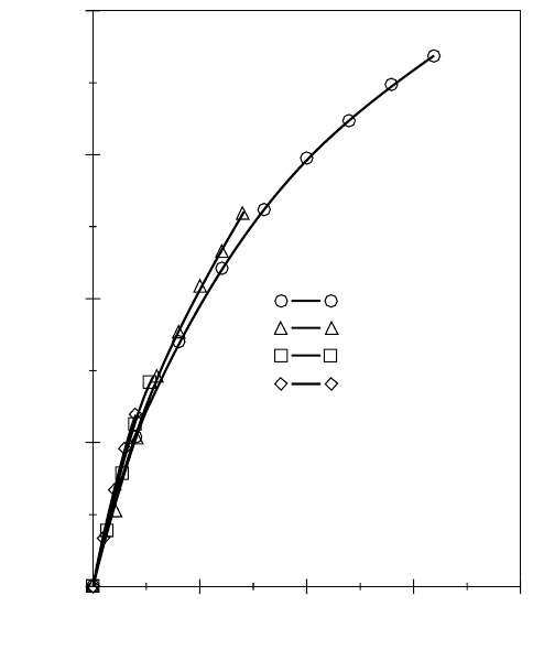
size. This is illustrated in Fig. 23.2, which shows some recent test results on footings of different size in a
fine sand. Generally, eccentric loading, inclined loading, footing shape, and foundation depth influence
the behavior of footings. Early on, Terzaghi developed the theoretical explanations to observed behaviors
into a “full bearing capacity formula,” as given in Eq. (23.24a) and applicable to a continuous footing:
(23.24a)
where r
u
= ultimate unit resistance of the footing
c ¢ = effective cohesion intercept
B = footing width
q ¢ = overburden effective stress at the foundation level
g¢ = average effective unit weight of the soil below the foundation
N
c
, N
q
, N
g
= nondimensional bearing capacity factors
The bearing capacity factors are a function of the effective friction angle of the soil. Such factors were
first originated by Terzaghi, later modified by Meyerhof, Berezantsev, and others. As presented in the
Canadian Foundation Engineering Manual [Canadian Geotechnical Society, 1985], the bearing capacity
factors are somewhat interrelated, as follows.
FIGURE 23.1 Contact stress vs. settlement of 150-mm footings. (Source: Vesic, 1967.)
0
20
40
STRESS (psi)
STRESS (kPa)
60
80
0.0 0.5 1.0 1.5 2.0
SETTLEMENT
2.5 3.0 (inch)
0
100
200
300
400
#61,
P
d
= 96.2 pcf
#62,
P
d
= 93.0 pcf
#63,
P
d
= 91.7 pcf
#64,
P
d
= 85.0 pcf
500
75 (mm)50250
r
u
c¢N
c
q¢ N
q
1–()0.5B
g
¢N
g
++=
© 2003 by CRC Press LLC
Foundations 23-13
(23.24b)
(23.24c)
(23.24d)
For friction angles larger than about 37∞, the bearing capacity factors increase rapidly and the
formula loses in relevance.
For a footing of width B subjected to a load Q, the applied contact stress is q (= Q /B) per unit length
and the applied contact stress mobilizes an equally large soil resistance, r. Of course, the soil resistance
can not exceed the strength of the soil. Equation (23.24a) indicates the maximum available (ultimate)
resistance, r
u
. In the design of a footing for bearing capacity, the applied load is only allowed to reach a
certain portion of the ultimate resistance. That is, as is the case for all foundation designs, the design
must include a margin of safety against failure. In most geotechnical applications, this margin is achieved
by applying a factor of safety defined as the available soil strength divided by the mobilized shear. The
available strength is either cohesion, c, friction, tan j, or both combined. (Notice that friction is not the
friction angle, j, but its tangent, tan j). However, in bearing capacity problems, the factor of safety is
usually defined somewhat differently and as given by Eq. (23.24e):
(23.24e)
where F
s
= factor of safety
r
u
= ultimate unit resistance (unit bearing capacity)
q
allow
= the allowable bearing stress
FIGURE 23.2 Stress vs. normalized settlement. (Data from Ismael, 1985.)
2000
1500
1000
B = 0.25 m
B = 0.50 m
B = 0.75 m
B = 1.00 m
STRESS (kPa)
500
0
0510
SETTLEMENT (%)
15 20
N
q
e
pj
¢tan
()
1
j
¢sin+
1
j
¢sin–
----------------------
˯
ʈ
=
j
¢ 0Æ N
q
1Æ
N
c
N
q
1–()
j
¢cot()=
j
¢ 0Æ N
c
5.14Æ
N
g
1.5 N
q
1–()
j
¢tan()=
j
¢ 0Æ N
g
0Æ
F
s
r
u
q
allow
§=
© 2003 by CRC Press LLC
23-14 The Civil Engineering Handbook, Second Edition
The factor of safety applied to the bearing capacity formula is usually recommended to be no smaller
than 3.0, usually equal to 4.0. There is some confusion whether, in the bearing capacity calculated
according to Eq. (23.24a), the relation (N
q
– 1) should be used in lieu of N
q
and, then, whether or not
the allowable bearing stress should be the “net” stress, that is, the value exceeding the existing stress at
the footing base. More importantly, however, is that the definition of factor of safety given by Eq. (23.24e)
is not the same as the factor of safety applied to the shear strength, because the ultimate resistance
determined by the bearing capacity formula includes several aspects other than soil shear strength,
particularly so for foundations in soil having a substantial friction component. Depending on the details
of each case, a value of 3 to 4 for the factor defined by Eq. (23.24e) corresponds, very approximately, to
a factor of safety on shear strength in the range of 1.5 through 2.0.
In fact, the bearing capacity formula is wrought with much uncertainty and the factor of safety, be it
3 or 4, applied to a bearing capacity formula is really a “factor of ignorance” and does not always guarantee
an adequate safety against failure. Therefore, in the design of footings, be it in clays or sands, the settlement
analysis should be given more weight than the bearing capacity formula calculation.
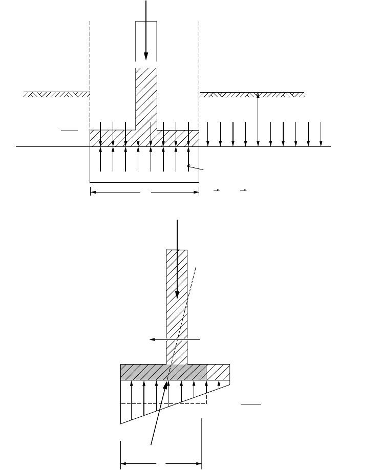
Footings are rarely loaded only vertically and concentrically. Figure 23.3(b) illustrates the general case
of a footing subjected to both inclined and eccentric load. Eq. (23.24a) changes to
(23.24f)
where factors not defined earlier are
s
c
, s
q
, s
g
= nondimensional shape factors
i
c
, i
q
, i
g
= nondimensional inclination factors
B¢ = equivalent or effective footing width
The shape factors are
(23.24g)
where L¢ = equivalent or effective footing length.
(23.24h)
The inclination factors are
(23.24i)
(23.24j)
An inclined load can have a significant reducing effect on the bearing capacity of a footing. Directly,
first, as reflected by the inclination factor and then also because the resultant to the load on most occasions
acts off center. An off-center load will cause increased stress, edge stress, on one side and a decreased
stress on the opposing side. A large edge stress can be the starting point of a failure. In fact, most footings,
when they fail, fail by tilting, which is an indication of excessive edge stress. To reduce the risk for failure,
the bearing capacity formula (which assumes a uniform load) applies the term B ¢ in Eq. (23.24f ), the
effective footing width, which is the width of a smaller footing having the resultant load in its center.
That is, the calculated ultimate resistance is decreased because of the reduced width (g component) and
the applied stress is increased because it is calculated over the effective area [as q = Q/(B¢/L¢)]. The
approach is approximate and its application is limited to the requirement that the contact stress must
not be reduced beyond a zero value at the opposite edge (“No tension at the heel”). This means that the
resultant must fall within the middle third of the footing, or the eccentricity must not be greater than B/6.
r
u
s
c
i
c
c ¢N
c
s
q
i
q
q¢N
q
s
g
i
g
0.5B ¢
g
¢N
g
++=
s
c
s
q
1 B¢ L¢§()N
q
N
c
§()+==
s
g
10.4B¢ L¢§()–=
i
c
i
q
1 d 90∞§–()
2
==
i
g
1
dj
¢§–()
2
=
© 2003 by CRC Press LLC
Foundations 23-15
When the load forms an angle with both sides of a footing or is eccentric in the directions of both
the short and long sides of the footing, the calculation must be made twice, exchanging B¢ and L¢.
The inclined load has a horizontal component and the calculation of a footing stability must check
that the safety against sliding is sufficient. The calculation is simple and consists of determining the ratio
between the horizontal and vertical loads, Q
h
/Q
v
. This ratio must be smaller than the soil strength
(friction, tan j¢, and/or cohesion, c¢ ) at the interface between the footing underside and the soil. Usually,
a factor of safety of 1.5 through 1.8 applied to the soil strength is considered satisfactory.
FIGURE 23.3 Input to the bearing capacity formula applied to a strip footing. (a) Concentric and vertical loading.
(b) Vertical and horizontal loading.
Q
h
q
q'
=
h
.
r
.
g
r
=
q
r
B
(a)
(b)
B
¢
N
c
N
q
N
g
,,
;
rg
¢
f
¢
q
=
Q
B
.
L
r
=
Q
V
B
¢
.
L
¢
Q
v
Q
H
© 2003 by CRC Press LLC
23-16 The Civil Engineering Handbook, Second Edition
In summary, the bearing capacity calculation of a footing is governed by the bearing capacity of a
uniformly loaded equivalent footing, with a check for excessive edge stress (eccentricity) and safety against
sliding. In some texts, an analysis of “overturning” is mentioned, which consists of taking the moment
of forces at the edge of the footing and applying a factor of safety to the equilibrium. This is an incorrect
approach, because long before the moment equilibrium has been reached, the footing fails due to excessive
edge stress. (It is also redundant, because the requirement for the resultant to be located within the
middle third takes care of the “overturning.”) In fact, “overturning” failure will occur already at a
calculated “factor of safety” as large as about 1.3 on the moment equilibrium. Notice that the factor of
safety approach absolutely requires that the calculation of the stability of the structure indicates that it
is stable also at a factor of safety very close to unity — theoretically stable, that is.
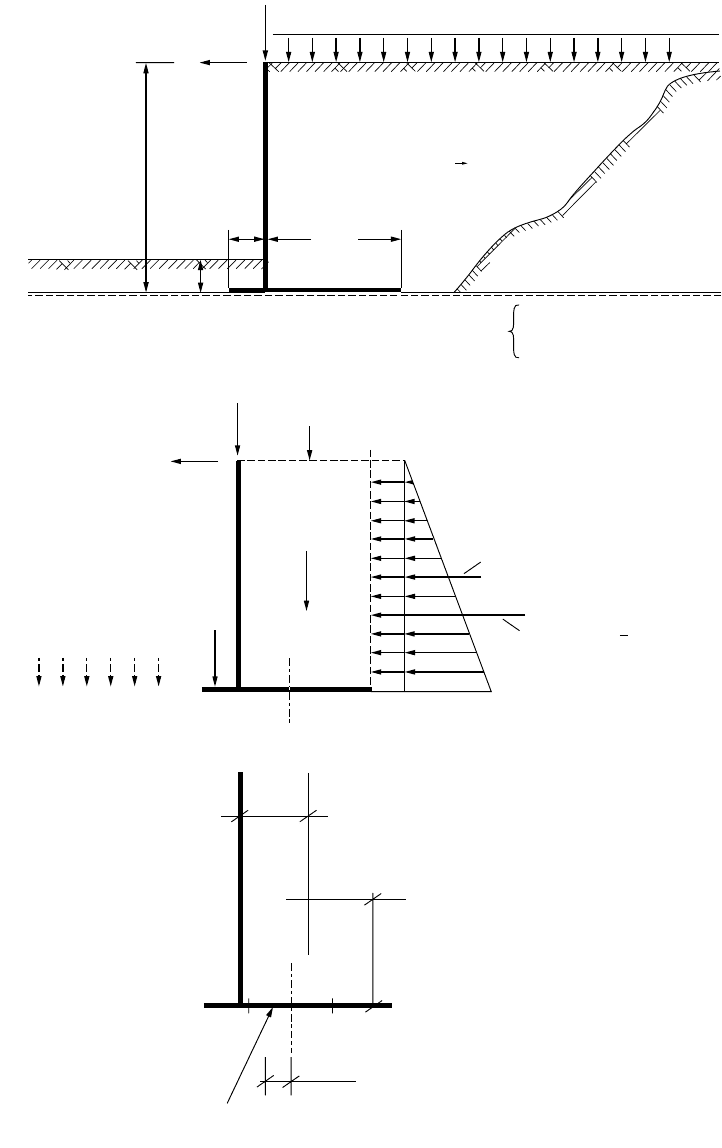
The bearing capacity calculations are illustrated in the example presented in Fig. 23.4. The example
involves a 10.0 m long and 8.0 m high, vertically and horizontally loaded retaining wall (bridge abutment).
The wall is placed on the surface of a “natural” coarse-grained soil and backfilled with a coarse material.
A 1.0 m thick backfill is placed in front of the wall and over the front slab. The groundwater table lies
close to the ground surface at the base of the wall. Figure 23.4(a) presents the data to include in an analysis.
In any analysis of a foundation case, a free-body diagram is necessary to ensure that all forces are
accounted for in the analysis, such as shown in Fig. 23.4(b). Although the length of the wall is finite, it
is normally advantageous to calculate the forces per unit length of the wall. To simplify the computations,
the weight of the slab and the wall is ignored (or the slab weight is assumed included in the soil weights,
and the weight of the wall [stem] is assumed included in the vertical load applied to the top of the wall).
The vertical forces denoted Q
1
and Q
2
are the load on the back slab of the wall. The two horizontal
forces denoted P
1
and P
2
are the active earth pressure forces acting on a fictitious wall rising from the
heel of the back slab, which wall is the boundary of the free body. Because this fictitious wall is soil, there
is no wall friction to consider in the earth pressure calculation. Naturally, earth pressure also acts on the
footing stem (the wall itself
). Here, however, wall friction does exist, rotating the earth pressure resultant
from the horizontal direction. Because of compaction of the backfill and the inherent stiffness of the
stem, the earth pressure coefficient to use for earth pressure against the stem is larger than active pressure
coefficient. This earth pressure is of importance for the structural design of the stem and it is quite
different from the earth pressure to consider in the stability analysis of the wall.
Figure 23.4(b) does not indicate any earth pressure in front of the wall. It would have been developed
on the passive side (the design assumes that movements may be large enough to develop active earth
pressure behind the wall, but not large enough to develop fully the passive earth pressure against the
front of the wall). In many projects a more or less narrow trench for burying pipes and other conduits
is often dug in front of the wall. This, of course, eliminates the passive earth pressure, albeit temporarily.
The design calculations show that the factors of safety against bearing failure and against sliding are
3.29 and 2.09, respectively. The resultant acts at a point on the base of the footing at a distance of 0.50 m
from the center, which is smaller than the limit of 1.00 m. Thus, it appears as if the footing is safe and
stable and the edge stress acceptable. However, a calculation result must always be reviewed in a “what
if
” situation. That is, what if for some reason the backfill in front of the wall were to be removed over a
larger area? Well, this seemingly minor change results in a reduction of the calculated factor of safety to
0.69. The possibility that this fill is removed at some time during the life of the structure is real. Therefore —
although under the given conditions for the design problem, the factor of safety for the footing is adequate —
the structure may not be safe.
Some words of caution: As mentioned above, footing design must emphasize settlement analysis. The
bearing capacity formula approach is very approximate and should never be taken as anything beyond
a simple estimate for purpose of comparing a footing design to previous designs. When concerns for
capacity are at hand, the capacity analysis should include calculation using results from in situ testing
(piezocone penetrometer and pressuremeter). Finite element analysis may serve as a very useful tool
provided that a proven soil model is applied. Critical design calculations should never be permitted to
rely solely on information from simple borehole data and N values (SPT-test data) applied to bearing
capacity formulas.
© 2003 by CRC Press LLC
Foundations 23-17
FIGURE 23.4 Bearing capacity example. (a) Problem background. (b) Free-body diagram. (c) Solution data.
(a)
(b)
(c)
100 kN/m
20 kN/m
15 kPa
4.5 m
100
20
30
1.91
0.50
3.28
1.5 m
W
Length,
L
= 10.0 m
1.0 m
8.0 m
r = 2000 kg/m
3
f = 32°
K
A
= 0.307
r = 2000 kg/m
3
N
c
= 38.64
N
q
= 26.09
N
g
= 24.44
Q
1
=
67.50
P
1
=
K
a
.
15.0
.
8.0 = 36.87
q
¢ = 20
P
2
=
K
a
.
20
. .
8
2
= 196.64
r
v
= 603 kPa
q
= 183 kPa
Q
2
=
720
f = 33° r = 1900 kg/m
3
;
c
L
1
2
Σ
Q
v
= 917.5
Σ
Q
H
= 253.52
s
c
=
s
q
= 1.04;
s
g
= 0.80
F
s
= 3.29 Bearing
F
s
= 2.09 Sliding
B
¢ = 5.0 m
L
¢ =
L
= 10.0 m
i
i
=
i
q
= 0.69
i
g
= 0.28
;
© 2003 by CRC Press LLC

23-18 The Civil Engineering Handbook, Second Edition
23.4 Pile Foundations
Where using shallow foundations would mean unacceptable settlement, or where scour and other envi-
ronmental risks exist which could impair the structure in the future, deep foundations are used. Deep
foundations usually consist of piles, which are slender structural units installed by driving or by in situ
construction methods through soft compressible soil layers into competent soils. Piles can be made of
wood, concrete, or steel, or be composite, such as concrete-filled steel pipes or an upper concrete section
connected to a lower steel or wood section. They can be round, square, hexagonal, octagonal, even triangular
in shape, and straight shafted, step tapered, or conical. In order to arrive at a reliable design, the particulars
of the pile must be considered, most important, the pile material and the method of construction.
Pile foundation design starts with an analysis of how the load applied to the pile head is transferred
to the soil. This analysis is the basis for a settlement analysis, because in contrast to the design of shallow
foundations, settlement analysis of piles cannot be separated from a load-transfer analysis. The load-
transfer analysis is often called static analysis or capacity analysis. Total stress analysis using undrained
shear strength (so-called a-method) has very limited application, because the load transfer between a
pile and the soil is governed by effective stress behavior. In an effective stress analysis (also called
b-method), the resistance is proportional to the effective overburden stress. Sometimes, an adhesion
(cohesion) component is added. (The adhesion component is normally not applicable to driven piles,
but may be useful for cast in situ piles). The total stress and effective stress approaches refer to both shaft
and toe resistances, although the equivalent terms, “a-method” and “b-method” usually refer to shaft
resistance, specifically.
Shaft Resistance
The general numerical relation for the unit shaft resistance, r
s
, is
(23.25a)
The adhesion component, c¢, is normally set to zero for driven piles and Eq. (23.25a) then expresses
that unit shaft resistance is directly proportional to the effective overburden stress.
The accumulated (total) shaft resistance, R
s
, is
(23.25b)
The beta coefficient varies with soil gradation, mineralogical com-
position, density, and soil strength within a fairly narrow range.
Table 23.3 shows the approximate range of values to expect from basic
soil types.
Toe Resistance
Also the unit toe resistance, r
t
, is proportional to the effective stress,
that is, the effective stress at the pile toe (z = D). The proportionality
coefficient has the symbol N
t
. Its value is sometimes stated to be of
some relation to the conventional bearing capacity coefficient, N
q
, but
such relation is far from strict. The toe resistance, r
t
, is
(23.26a)
The total toe resistance, R
t
, acting on a pile with a toe area equal to A
t
is
(23.26b)
r
s
c ¢
bs
¢
z
+=
R
s
A
s
r
s
zd
Ú
A
s
c ¢b
s
¢
z
+()zd
Ú
==
TA BLE 23.3 Approximate
Range of Beta Coefficients
Soil Type Phi Beta
Clay 25-30 0.25-0.35
Silt 28-34 0.27-0.50
Sand 32-40 0.30- 0.60
Gravel 35-45 0.35-0.80
r
t
N
t
s¢
zD=
.
=
R
t
A
t
r
t
A
t
N
t
s¢
zD=
.==
© 2003 by CRC Press LLC
Foundations 23-19
In contrast to the b-coefficient, the toe coefficient, N
t
, varies widely.
Table 23.4 shows an approximate range of values for the four basic soil
types.
Ultimate Resistance — Capacity
The capacity of the pile, Q
ult
(alternatively, R
ult
), is the sum of the shaft
and toe resistances.
(23.27)
When the shaft and toe resistances are fully mobilized, the load in pile, Q
z
, (as in the case of a static
loading test brought to “failure”) varies, as follows:
(23.28)
Equation (23.28) is also called the resistance distribution curve. At the depth z = D, Eq. (23.28), of
course, states that Q
z
= R
t
.
Notice that the commonly used term “ultimate capacity” is a misnomer and a tautology: a mix of the
words “ultimate resistance” and “capacity”. Although one cannot be mistaken about the meaning of
ultimate capacity, the adjective should not be used, because it makes other adjectives seem proper, such
as “load capacity,” “allowable capacity,” “design capacity,” which are at best awkward and at worst mis-
leading, because what is meant is not clear. Sometimes not even the person using these adjectives with
“capacity” knows the meaning.
During service conditions, loads from the structure will be applied to the pile head via a pile cap. The
loads are normally permanent (or “dead”) loads, Q
d
, and transient (or “live”) loads Q
l
. Not generally
recognized is that even if soil settlement is small — too small to be noticeable — the soil will in the
majority of cases move down in relation to the pile and in the process transfer load to the pile by negative
skin friction. (The exception refers to piles in swelling soils and it is then limited to the length of pile in
the swelling zone.) Already the extremely small relative movements always occurring between a pile shaft
and the soil are sufficient to develop either shaft resistance or negative skin friction. Therefore, every pile
develops an equilibrium of forces between, on the one side, the sum of dead load applied to the pile
head, Q
d
, and dragload, Q
n
, induced by negative skin friction in the upper part of the pile, and, on the
other side, the sum of positive shaft resistance and toe resistance in the lower part of the pile. The point
of equilibrium, called the neutral plane, is the depth where the shear stress along the pile changes over
from negative skin friction into positive shaft resistance. This is also where there is no relative displacement
between the pile and the soil.
The key aspect of the foregoing is that the development of a neutral plane and negative skin friction
is an always occurring phenomenon in piles and not only of importance in the context of large settlement
of the soil around the piles.
Normally, the neutral plane lies below the midpoint of a pile. The extreme case is for a pile on rock,
where the location of the neutral plane is at the bedrock elevation. For a dominantly shaft-bearing pile
“floating” in a homogeneous soil with linearly increasing shear resistance, the neutral plane lies at a depth
which is about equal to the lower third point of the pile embedment length.
The larger the toe resistance, the deeper the elevation of the neutral plane. And, the larger the dead
load, the shallower the elevation of the neutral plane.
The load distribution in the pile during long-term conditions down to the neutral plane is given by
the following load-transfer relation. [Below the neutral plane, Q
z
follows Eq. (23.28).]
(23.29)
TABLE 23.4 Approximate
Range of N
t
Coefficients
Soil Type Phi N
t
Clay 25-30 3–30
Silt 28-34 20–40
Sand 32-40 30–150
Gravel 35-45 60–300
Q
ult
R
s
R
t
+=
Q
z
Q
u
A
s
bs
¢
z
zd
Ú
– Q
u
R
s
–==
Q
z
Q
d
A
s
q
n
zd
Ú
+ Q
d
Q
n
+==
© 2003 by CRC Press LLC