Warnick C.C. Hydropower engineering
Подождите немного. Документ загружается.

8
Hydraulics
of
Hydropovver Chap.
3
V3
=
water velocity at point 3, ft/sec
p3
=
pressure at point 3,1b/ft2
Z3
=
potential head at point 3, ft
h
=
effective head on turbine, ft.
lathematically, then, the Bernoulli equation states that the sum of the component
nergies (position energy, pressure energy, and kinetic energy) is constant in a
con-
ned moving fluid as the fluid moves along its path. Thus a change in any one of
le component energies at any point aiong the path of the moving fluid must be
ompensated for by an equal change of the water energy components at that point.
his mathematical development assumes no friction or head loss in the fluid moving
om point
1
to point 2 as shown in Fig. 3.2.
In
a practical sense, there is friction
)ss or
head
loss,
hfi
in the case of water flowing from point
1
to point 2. Thisis
;counted for in tlie graphical representation shown in Fig. 3.3.
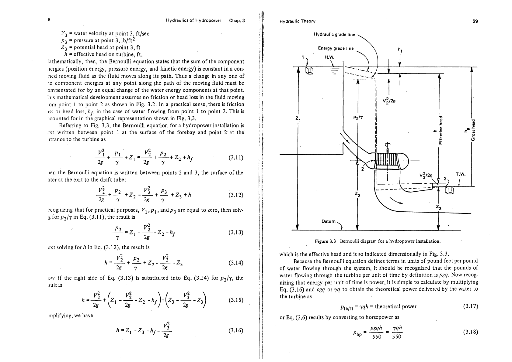
Referring to Fig. 3.3, the Bernoulli equation for a hydropower installation is
rst written between point 1 at the surface of the
forebay
and
point
2
at the
iltrance to the turbine as
hen the Bernoulli equation is written between points 2 and 3, the surface of the
ater at the exit to the draft tube:
:cognizing that for practical purposes, V1,
pl,
and
p3
are equal to zero, then solv-
g
for
p2/y
in
Eq.
(3.1 l), the result is
sxt solving for
11
in Eq. (3.12), the result is
o\v
if tlie right side of Eq. (3.13) is substituted into Eq. (3.14) for
p2/7,
the
sult is
mplifying, we have
i
I
Hydraulic Theory
Hydraulic grade line
\
Energy grade line
Figure
3.3
Bernoulli diagram for a hydropower installation.
which is the effective head and is
50
indicated dimensionally in Fig. 3.3.
Because the Bernoulli equation defines terms in units of pound feet per pound
of water flowing through the system, it should be recognized that the pounds of
water flowing through the turbine per unit of time by definition is
pgq.
Now recog-
nizing that energy per unit of time is power, it is simple to calculate by multiplying
Eq.
(3.16) and
pgq
or
yq
to obtain the theoretical power delivered by the water to
the turbine as
plblft
=
yqh
=
theoretical power (3
.I
7)
or Eq. (3.6) results by converting to horsepower as
30
Hydraulics
of Hydropower
Chao.
3
The energy equation in the Bernoulli fornl, as given in Eqs.
(3.10)
and
(3.1
1)
and illustrated in Fig.
3.3
relating cficctive head to the energy gradc line and the
hydraulicgrade line, should be
refcrred to oficn to understand the many concepts
of hydropower engineering.
KINETIC
THEORY
Further theory related to the speed of the runner and the dynamic action of the
water on the buckets and vanes is important for understanding the energy-converting
action and is necessary in developing certain turbine constants that are used in the
design and selection of runners.
Impulse Runner Force
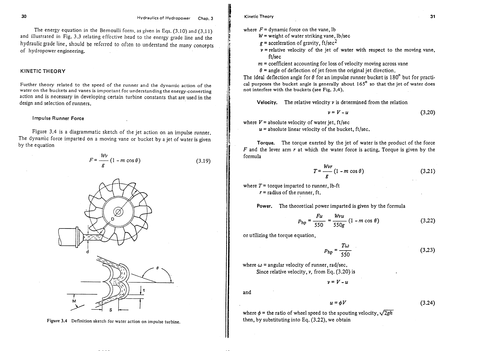
Figure
3.4
is a diagrammatic sketch of the jet action on an impulse runner.
The dynamic force imparted on a moving vane or bucket by a jet of water is given
by the equation
Figure
3.4
Definition sketch for water action on impulse turbine
Kinetic
Theory
where
F
=
dynamic force on the vane, lb
W
=
weight of water striking vane, lb/sec
g
=
acceleration of gravity, ft/sec2
v
=
relative velocity of the jet of water with respect to the moving vane,
ft/sec
m
=
coefficient accounting for loss of velocity moving across vane
9
=
angle of deflection of jet from the original jet direction.
The ideal deflection angle for
8 for an impulse runner bucket is 180' but for practi-
cal purposes the bucket angle is generally about
165'
so that the jet of water does
not interfere with the buckets (see Fig.
3.4).
Velocity.
The relative velocity
v
is determined from the relation
v=
v-u
where
V
=
absolute velocity of water jet, ft/sec
u
=
absolute linear velocity of the bucket, ft/sec.
Torque.
The torque exerted by the jet of water is the product of the force
F
and .the lever arm
r
at which the water force is acting. Torque is given by the
formula
Wvr
T
=
-
(1
-
m
cos 8)
g
where
T=
torque imparted to runner, lb-ft
r
=
radius of the runner, ft.
Power.
The theoretical power imparted is given by the formula
-
Fu Wvu
-
php
-
550
-
-
(1
-
m
cos 9)
ssog
or utilizing the torque equation,
where
w
=
angular velocity of runner, rad/sec.
Since relative velocity,
v,
from Eq. (3.20) is
and
where
4
=
the ratio of wheel speed to the spouting velocity,
then, by substituting into Eq.
(3.22), we obtain
Hydraulics
of Hydropower
Chap.
3
rv
v2
Php
=
-
(1
-
$)($)(I
-
m
cos
8)
550
(3.7
5)
it
the operating point of maxilnuln power and best speed, the relative velocity of
,iater initially striking the bucket is
Yl
=
V-11
nd the relative velocity leaving the bucket is
v2
=
ttwl
=
m(V
-
u)
(3.2
7)
it the best turbine speed, v2 has no tangential co~npoilent of velocity and
Vtn
cos
e
LI
=
m
cos
0
-
1
.~bstituting into Eq.
(3.22)
-
W
php
-
-
(V
-
u)(rr)(l
-
m
cos
0)
5 50
5
50
(1
-
m
cos
8)
- -
wv2
tn
cos
e
550 m
cos
0
-
1
Best linear velocity.
The best linear speed of the turbine can be determined
sing
Eq.
(3.29)
and
v=cdm
(3.3
1)
here
Cd
=velocity coefficient and tlie~l using Eq.
(3.29)
m
cos
0
1d=cdm
??I
cos
0
-
1
Jr example, if
Cd
=
0.98, tn
=
0.96,
and
$
=
165'
Kinetic
Theory
(0.96)
cos
165'
u
=
0.98
6
0.96
cos
165"
a
Jet diameter.
Jet diameter can be determined using the equation
where
q
=jet discharge in ft3/sec
A
=
area of the jet
in
ft2
di
=jet diameter in ft
and
for
then
Cd
=
0.98
as usual value
q1/2
di
=
0.402
-
h
114
Bucket spacing.
In
Fig.
3.2
it can be noted that if wheel diameter is known,
the spacing for buckets can be determined by the simple equation
where.s
=
bucket spacing, in.
Runner diameter.
Brown and Wkippen
(1972)
indicate that a good rule of
thumb for impulse turbines is to
make the diameter of the runner in feet equal to
the diameter of the jet in inches. However, the ratio of the diameter of the runner
to the diameter of the jet in feet will vary from a low of
9
for low-head impulse
turbines to a high of
18
for high-head impulse turbines. The ratio is Limited by the
pllysical restraints of attaching the buckets to the disk.
Reaction Runner Flow
For a reaction runner, the torque
(T)
imparted by the water to the runner is
given
by
the equation.
34
Hydraulics of Hydropower Chap.
3
where
W
=
yq
=
quantity of water flowing, Ib/sec
rl
=
radius of runner in feet at thc periphery where the water first strikes
the runner vane, ft
V1
=absolute velocity of the water at the entrance to the runner, ftlsec
crl
=angle that the absolute velocity vector
V,
makes with tangent to the
runner circumference
r2
=
radius of the runner in feet at point where water leaves the runner, ft
V2
=
absolute velocity of water at the exit to the runner, ft/sec
cr2
=
angle that the absolute velocity vector
V2
makes with tangent to runner
circumference.
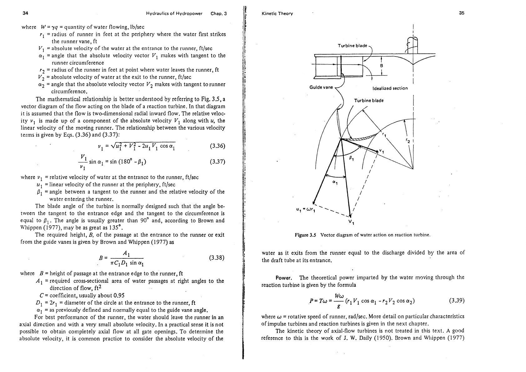
The mathematical relationship is better understood by referring to Fig. 3.5, a
vector diagram of the flow acting on the blade of a reaction turbine. In that diagram
it is assumed that
the flow is two-dimensional radial inward flow. The relative veloc-
ity
v,
is made up of a component of the absolute velocity
V1
along with
u,
the
linear velocity of the moving runner. The relationship between the various velocity
terms is given by Eqs. (3.36) and (3.37):
v1
=
du?
+
V?
-
25 Vl
cos
a1
(3.36)
"1
.
-
sln
a1
=
sin (180'
-PI)
1
where
vl
=
relative velocity of water at the entrancc to the runner, ftlsec
u,
=linear velocity of the runner at the periphery, ftlsec
P1
=
angle between a tangent to the runner and the relative velocity of the
water entering the runner.
The blade angle of the turbine is normally designed such that the angle be-
tween the tangent to the entrance edge and the tangent to the circumference is
equal to
PI.
The angle is usu.ally greater than 90' and, according to Brown and
n'ldppen
(1977),
may be as great as 135'.
The required height,
B,
of the passage at the entrance to the runner or exit
from the guide vanes is given by Brown and
Whippen (1977) as
B
=
A
1
,
nCIDl
sin
al
where
B
=
height of passage at the entrance edge to the runner, ft
A1
=required cross-sectional area of water passages at right angles to the
direction of flow, ft2
C
=
coefficient, usually about 0.95
Dl
=
2rl
=
diameter of the circle at the entrance to the runner, ft
=
as previously defined and normally equal to the guide vane angle.
For best performance of the runner, the water should leave the runner in an
axial direction and with a very small absolute velocity. In a practical sense it is not
possible to obtain
conlpletely axial flow at all gate openings. To determine the
absolute velocity, it is common practice to consider the absolute velocity of the
Kinetic Theory
Guide vane
Idealized section
Turbine blade
1
Figure
3.5
Vector
diagram of water action on reaction turbine.
water as it exits from the runner equal to the discharge divided by the area of
the draft tube at its entrance.
Power.
The theoretical power imparted by the water moving through the
reaction turbine is given by the formula
where
w
=
rotative speed of runner, radlsec. More detail on particular characteristics
of impulse turbines and reaction turbines is given in the next chapter.
The kinetic theory of axial-flow turbines is not treated in this text.
A
good
reference to this is the work of
J.
W.
Daily (1950). Brown and Whippen (1977)
36
Hydraulics of Hydropower
Cha~.
3
!ndicate that
the
absolute velocity of water discharged from the runner of a pro-
!,elJcr turbine rallges
from
4
to
6
fi,
where
h
is the effective head.
Tllc absolute velocity,
ITl,
at the entrance to the reaction turbine runner is
related to
effective
head by the formula
v1
=cvm
(3.4
0)
,vhere c,:
=
velocity coefficient. For reaction turbines, Brown and \Vhippen
(1977)
ndicate [hat
r
valies
between
0.8
and
0.6.
The
at~glc
0,
between the tangent to the circular path of a point on the
~eripllery
of
tl~c
runner
at
the entrance and the direction of the water entering the
unner and
passjr~g the guide vsnes (see Fig. 3.5) ranges fronl 15'
to
35'. It is often
irsumed that the relative velocity of the water leaving the runner blade is in the
,ame
dir-ction as the blade angle at the exit. The magnitude of the relative velocity
]la), be compured by dividing the discharge,
q,
by the total exit area of the runner
Image 3t rigl~t angles
to
the blade edges. In modern turbines that area would be a
cry
colrlples surface, but for a truly radisl flow runner
it
would be a cylindrical
(rea eqt13l.to
3nr2B
(see Fig. 3.5).
Z
EFERENCES
{rowli,
L.
P.,
~nd
\V.
E.
Whippen,
IIydra~rlic Turbines,
Parts 1 and
2.
Scranton, Pa.:
Interndrlo~~j! Textbook Car~lpany, 1972, 1977.
)ail?,
J.
\V.,
"I-lyclraulic hlachinery." Chapter
XI11
in
Eilgi~~eering Hydraulics,
H.
Rollrc.
:d.
S?w
York: John \ffilcy
S:
Sons, Inc., 1950.
'ROBLEMS
!.I.
Show \vhy the maximum theoretical power from an impulse turbine would
occur
\\.lien the bucket angle is
8
=
1 80°, and explain why net head for such a
tlirbilie
is
taken only to the centerline elevation of the jet striking the turbine
buckets.
2
.An i~iip~~lse turbine is to be used to develop the energy at a site where water
discharge
q
=
20 ft3/sec and the effective head is 980
ft.
Using theoretical and
e~i?pirica! <cluations presented in this chapter, find the following:
(a)
Kequircd jet dialiieter for a single jet
jb) .-\ppro.<mate runller diameter
(c) Tli<orr.tic;~l best linear speed of runner
(d)
;\bsolute velocity of water at impact with runner
(e) Relative velocity of water striking the runner
(f)
Tlicn~.etical torque imparted by the water
to
the runner
(g)
Theoretical
output of runner, in horsepower.
Assullie [lie deflection angle to be 130~.
Chap.
3
Problems
.
37
3.3.
A reaction turbine with an estimated overall efficiency of 0.91
is
to utilize
500
ft3/sec of water, operating at a synchronous speed of 450 rpnl under 3n
effective head of 200 ft. If the acute angle between the guide vane and a
tangent to the outer
periphery of the runner
is
30' and the runner diameter
at the entrance is
3.83
ft, determine the following:
(a)
Absolute velocity at entrance
if
the coefficient of velocity is assumed to
be 0.80
(b)
Linear speed of a point on the runner at the entrance to the runner
(c)
Relative velocity of water at the entrance edge of the runner bucket
(d) Runner blade angle,
0
(e) Approximate height at the entrance edge of the runner
(f)
Output of the turbine in horsepower and kilowatts
(g)
Torque to be delivered by the turbine shaft
3.4
Would it be possible in Problem 3.3 to find the relative velocity of the water
exiting the runner with information given and discussed in the text?
SIMILARITY LAWS
Similarity
laws
have been developed for characterizing turbine performance of units
of different size and type. They provide a means of predicting performance based
on the perforrnancc of
lnodels or the performance of units of design sindar to
those that have already been built.
The fact that the similarity laws can be used is
oiten referred to as the
llomologous
nature of turbines. When turbines of different
sizes are designed to have
correspa~iding linear dimensions with a common geo-
metric ratio, the
turbines are said to be homologous. The power outputs, speeds,
and flow characteristics are proportional
and they tend to have equal efficiencies.
These similarity laws are developed and presented in a series of formulas that define
what are called the
turbirie constants.
The equations are derived from fundanlental
physical concepts of motion and hydraulic theory.
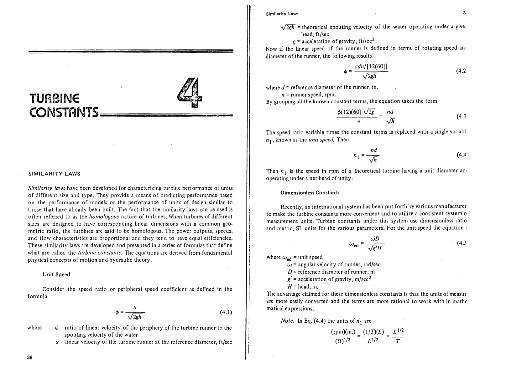
Unit Speed
Consider
the speed ratio or peripheral speed coefficient as defined in the
formula
where
r$
=
ratio of linear velocity of the periphery of tlie turbine runner to the
spouting velocity of the water
u
=
linear velocity of the turbine runner at the reference diameter, ft/sec
Similarity
Laws
3
&$
=theoretical spouting velocity of the water operating under a give,
head,
ft/sec
g
=
acceleration of gravity, ft/sec2.
Now if the linear speed of the runner is defined in terms of rotating speed
an1
diameter of the runner, the following results:
where
d
2
reference diameter of the runner, in.
n
=
runner speed, rpm.
By grouping
all
the known constant terms, the equation takes the form
The speed ratio variable times the constant terms is
r'eplaced with a single variabl
n
known as the
unit
speed.
Then
Then
nl
is the speed in rpm of a theoretical turbine having a unit diameter ant
operating under a net head of unity.
Dimensionless Constants
Recently, an international system has been put forth by various manufacturer
to make
tlie turbine constants more convenient and to utilize a consistent system o
measurement units. Turbine constants under this system use
dimensionless
ratio
and metric,
SI,
units for the various parameters. For the unit speed the equation
i
where
wd
=
unit speed
w
=
angular velocity of runner, radlsec
D
=
reference diameter of runner, m
g'
=
acceleration of gravity, m/sec2
H
=
head, m.
The advantage claimed for these dimensionless constants is that the units ofmeasur
are more easily converted and the terms are more rational to work with in mathc
matical expressions.
Note.
In
Eq.
(4.4)
the units of
nl
are
40
Turbine Constants Chap.
4
where
T=
time units
L
=
length
units,
while
in
Eq.
(4.5)
the ~tnits of
wed
are
This
is
a
ratio of the peripheral speed of the runner to the theoretical spouting
velocity of the water.
Unit
Discharge
The unit
discllarge equation is developed in a similar manner, as follows:
4
=
F(A,
~z)=cA~
(4
-6)
wllere
q
=
design discharge flowing through turbine, ft3/sec
A
=
circular area opening at the exit from
the
runner through which water
passes, ft2
C
=
an orifice-type coefficietlt relating flow to head and area
A.
\jrriting this in terms
of
diameter of the runner in inches, the following equation
results:
By
~roupins 311 constant terms on otie side, the equation takes the form
Then
ql
is the discharge of a runner with unit diameter operating under a unit
!lead. The corresponding dinlensionless unit discharge specified
by
international
,tandards is
as
follows:
where
QCd
=
utiit discharge
Q
=
design
discllarge flowing through turbine, n13/sec.
Similarity
Laws
Unit
Power
The
unit power equation is developed from
the
following:
where
p
=
turbine power output, hp
p
=
density of water, slugs/ft3
q
=
turbine overall efficiency
550
=
number of ft-lb/sec in
1
hp.
By
substituting the value of
q
=
qld2
fi
from Eq.
(4.9)
in Eq. (4.1
l),
the following
results:
By grouping the variable
ql
and all the constant terms as before,
the
equation has
the form
Then
fi
is the power produced by a runner with a unit diameter operating under a
unit head. The corresponding dimensionless unit power term
is
D
where
Pd
=
unit power, dimensionless
P=
turbine power output, watts
=
mass density of water, kgim3
g'
=
acceleration of gravity, m/sec2.
Specific Speed
To develop a more universal constant that embodies all the equations, it is
necessary to operate on Eqs.
(4.4).and (4.13). The value of
d
equal to
nl
&/n
from Eq. (4.4) is introduced in Eq. (4.1
3)
so that the following equation results:
Grouping the
nl
and
pl
on one side of the equation, the following results:
42
Turbine Constants Chap.
4
Taking the square root of both sides of the equation gives the term
n,,
the specific
spced, as follows:
Then
n,
is the specd of a unit producing unit output under a head of unity.
In
cornrl-ror~ usage in Europe is a similar form of the specific speed:
where
N,
=
specific speed, units of rpm,
kW,
and m
hf
=
rotational speed of turbine, rpm
P=
power output at best efficiency,
kW
H
=
net head, m.
Note.
Capital letters are used when metric SI units are used.
The corresponding term from the dimensionless-type constant has been altered
to include in
the definition the turbine discharge rather than the power output. The
dzveloprnent is described below:
First,
Eq.
(3.9) is modified to express power in watts as
P
=
P'~'QH~).
This is
tlien i!itroduced inlo Eq. (4.14) so that
Now the value
wed
m/w
is substituted for
D
in
Eq.
(4.1 9), giving the following:
By
grouping
Ped,
oed,
and
t)
on one side, the equation takes the form
Taking the square root of both sides of the equation gives the equation for
tlie diri~ensionless specific speed:
\vliere all units are as defined before in the metric
SI
system.
Tlus is the form of the specific speed equation that is being advocated for
international standardization. In addition to this form, Csanady (1964) reports the
specific speed i11 a similar form as follows:
Similarity
Laws
where
52
=
specific speed
w
=
angular velocity of runner, rad/sec
q
=water discharge, ft3/sec
g
=
acceleration of gravity, ft/sec2
h,
=net head, ft.
Other variations of the turbine constants with relation to torque have been
developed for ease of analyzing certain characteristics of turbines. Table 4.1 is a
summary of
tlie various forms of the turbine constants giving the equation for each
and conversions for converting the specific speed from one system to another.
A
specific speed may be calculated for any point of turbine operation, but the usual
specific speed of a turbine is defined as that value calculated at the point of peak
efficiency. Not shown in the table is the equation presented by
Csanady (1964),
Eq. (4.23). Csanady shows that
R
=
n,/42.
However, this is true only if the turbine efficiency,
q,
is 93.2%, while in
actuality, it can be shown that
where
71
='turbine efficiency. By substituting
w
=
2nn/60
and
q
=
t/wfrom
Eq. (3.8) in
Eq.
(4.23) we have
-
7
Rearranging terms, we have
but
-
from
Eq.
(4.1
7)
so
that
A
similar development shows the relation between
w,
and
ns,
since from Eq. (4.22)
Then by substituting
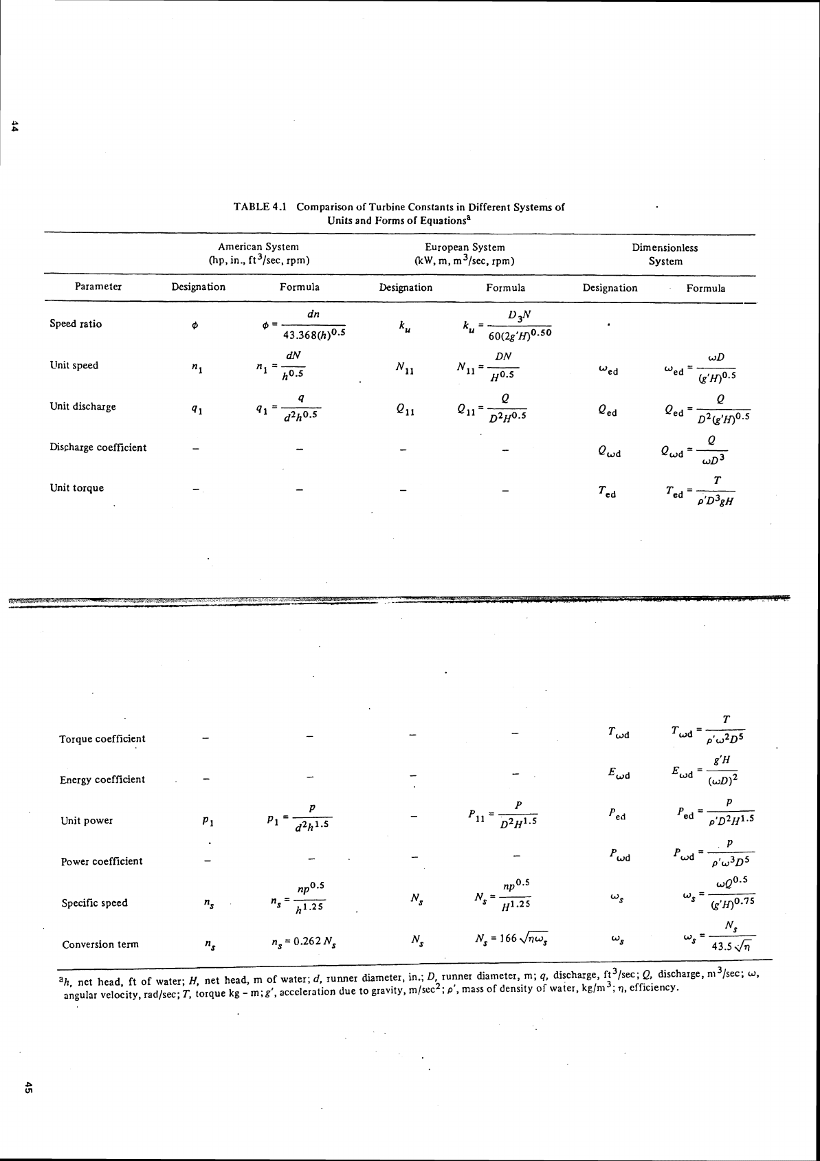
TABLE
4.1
Comparison of Turbine Constants in Different Systems of
Units and Forms of Equationsa
- --
American Systenl European System Dimensionless
(hp, in., ft3/sec, rpm)
RW,
m, m3/sec, rpm) System
Parameter Designation Formula Designation Formula
Designation Formula
Speed ratio
@
Unit speed
1
Unit discharge
41
Dis~harge coefficient
-
Unit torque
-
Q
Qwd
QWd
=
-
WD
Torque coefficient
Energy coefficient
.
P
P
P
Unit power
-
p1
Pll
=-
Pe
,i
Pe,
=
-
P1
=-
D2Hl.5 ,'~2~1.5
P
Power coefficient
-
-
-
-
Pwd
Pwd
=
--
P'U~D~
npoa5 nPo5 ~QO-~
Specific speed
"s
n,
=
-
Ns
Ns
=
-
Ws
=
-
h1.25
.
~1
.25 k~,j)0.75
~,=1666
Nf
Ns
"
=
-----
Conversion term
"s n,
=
0.262 N,
43.56
Ih. net head, ft of wafer;
ff,
net head,
m
of water;
d,
runner diameter,
h.:
D,
runner diameter, m;
q,
discharge, ft3/scc;
Q,
discharge, n13/sec;
w,
angular velocity, rad/sec;
T,
torque
kg
-
m;gr,
acceleration
due to gravity, m/scc2;
P',
mass of density of water, kg/n13;
q,
efficiency.
46
Turbine Constants Chap.
4
from
Eq.
(3.9) and
in
Eq.
(4.22) we have
Inserting
P
=
0.746
p
and
Ij
=
0:3048
17
in order to convert kilowatts to horse.
power and meters to feet, and collecting
ternis we have
but
from
Eq.
(4.17)
Therefore
TURBINE CONSTANTS
AND
EMPIRICAL EQUATIONS
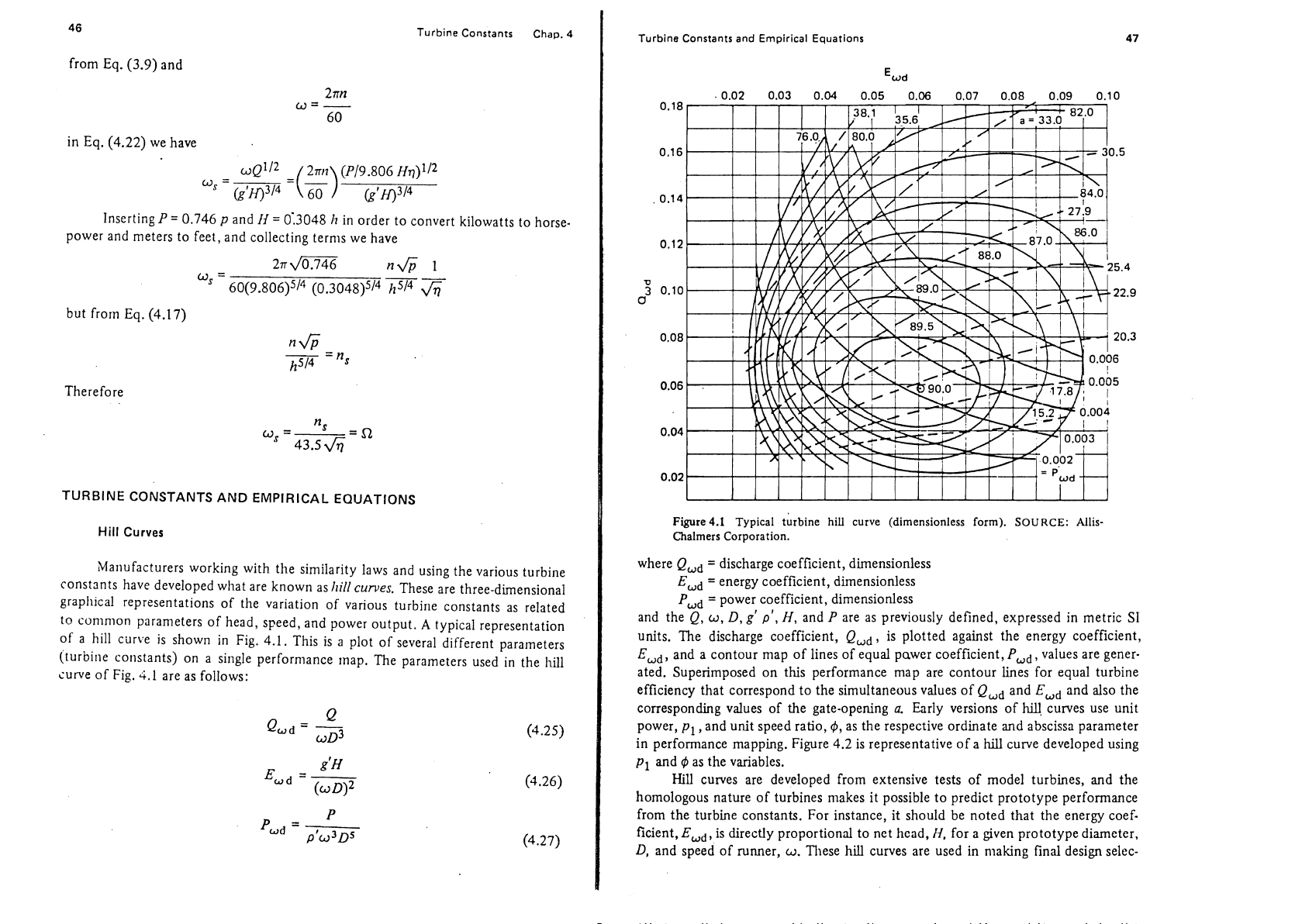
Hill Curves
Ma~lufacturers working with the similarity laws and using the various turbine
constants have developed
what are known as
hill
curves.
These are three-dimensional
grapllical representations of the variation of various turbine constants as related
to common parameters of head, speed, and power output.
A
typical representation
of a hill curve is shown in Fig. 4.1. This is a plot of several different parameters
(turbine
co~istants) on a single performance map. The parameters used in the hill
curve of Fig.
4.1
are as follows:
Turbine Constants and Empirical Equations
47
+--t-+
-
'wd
+i
Figure4.1
Typical tlrbine
hill
curve (dimensionless form).
SOURCE:
Allis-
Chalmers Corporation.
where
QUd
=
discharge coefficient, dimensionless
Ewd
=
energy coefficient, dimensionless
Pwd
=
power coefficient, dimensionless
and the
Q,
w,
D,
g'
p',
H,
and
P
are as previously defined, expressed in metric S1
units. The discharge coefficient,
Qwd,
is plotted against the energy coefficient,
Ewd,
and a contour map of lines of equal pawer coefficient,
PUd,
values are gener-
ated. Superimposed on this performance map are contour
lines for equal turbine
efficiency that correspond to the simultaneous values of
Qwd
and
Ewd
and also the
corresponding values of the gate-opening
a.
Early versions of
hilJ
curves use unit
power,
pl
,and unit speed ratio,
$,
as the respective ordinate and abscissa parameter
in
performance mapping. Figure
4.2
is representative of a
hill
curve developed using
PI
and
4
as the variables.
Hill
curves are developed from extensive tests of model turbines, and the
homologous nature of turbines
makes it possible to predict prototype performance
from the turbine constants. For instance, it should be noted that the energy
coef.
ficient,
Ewd,
is directly proportional to net head,
N,
for a given prototype diameter,
D,
and speed of runner,
a.
These hill curves are used in making final design selec-