Water Power and Dam Construction. Issue February 2010
Подождите немного. Документ загружается.


WWW.WATERPOWERMAGAZINE.COM FEBRUARY 2010 41
FLOOD MANAGEMENT
K
INLOCH Rannoch Weir is located at the head of
Loch Rannoch in Scottish & Southern Energy’s (SSE)
Tummel hydroelectric scheme and controls 1.637Mft
3
of water. The Tummel Valley is well suited to a hydro-
electric scheme, representing a large catchment area of 1839km
2
,
with heavy annual rainfall. Its potential was recognized by the
Grampian Electricity Supply Company which built power stations
at Rannoch and Tummel Bridge in the 1930s.
The weir consists of three 12.2m wide floodgates which were installed
in the 1930s and are to be replaced under this contract. The three weir
gates at Kinloch Rannoch Weir control the flow of water from Loch
Rannoch, and are of the undershot design. Originally designed, con-
structed and installed by Glenfield & Kennedy they are almost 80 years
old and last year it was agreed they were in need of replacement.
Site Services, a division of Enterprise Engineering Services, the
Aberdeen based engineering and fabrication services specialist, won
the contract in May 2009. The Site Services division delivers onsite
repair and maintenance across a wide range of sectors including
hydro power, water control and the paper industries.
During the first few months of the Kinloch Rannoch Weir con-
tract, the team undertook a detailed design phase and produced a 3D
model of the gates in its Aberdeen workshop. It is anticipated that
construction of gate one will be complete by the end of January 2010
(as we go to press) with installation following soon after.
A team of 10 staff from Site Services are involved in the ongoing
project including project manager, construction manager, site super-
visor, onsite engineers / welders, onsite electricians and manufactur-
ing staff in the Aberdeen workshop. Kinloch Rannoch Weir is, to
date, the biggest project the team has worked on.
CLIENT OBJECTIVES
Prior to the commencement of the design phase, several discussions took
place between Sites Services and the client to agree key objectives:
UÊ The gate should be designed to meet modern standards and provide
an adequate design life based on the latest wave and flood model-
ling data available.
UÊ The design of the gates must comply with modern design codes
whilst still maintaining the original dimensions and weight restric-
tions of the existing civil works
UÊ The mass of the new gate assembly should be no greater than the
existing gate, as SSE wanted to retain the existing refurbished lifting
gear without modification
UÊ The new gate should be manufactured in several parts and subsequently
re-assembled in situ, due to the SWL limitation on the overhead gantry
system and the physical constraints of the existing civil works (i.e. the
existing gate had been installed prior to the fitment of the headgear)
DESIGN AND INSTALLATION
Although much of the work being carried out by Site Services is rou-
tine and has been completed many times before, the design phase has
been particularly challenging as the replacement gates must comply with
modern design codes whilst still maintaining the original dimensions and
weight restrictions of the existing civil works. Finite Element modelling
methods have been used in the design to cover the many load cases,
including the requirement for seismic loadings to be taken into account.
Site load lifting limitations have also constrained the design of the
gate to be of a three part modular construction employing bolted
seams to complete the construction.
A bespoke overhead gantry system has been designed and installed
by SSE to permit the installation of the stoplogs.
The SWL of the overhead gantry system, based on the maximum
mass of a single stoplog, is 5 tonnes.
It was agreed by the team that this overhead gantry system would
also need to be used to install the replacement gates as separate cra-
neage access to the site is difficult.
Site Services manufactured a three part modular construction
employing bolted seams to complete the construction due to the site
load lifting limitations.
THE FUTURE
Site Services aims to deliver its part of the project on time and
within budget despite the challenges it is being faced with. The team
attributes its on-going successful completions of other projects to
great communication and working closely with the main contractor
to achieve goals.
More about Enterprise Engineering and its divisions can
be found at www.eesl.com or by calling 01224 288400 or
emailing sales@eesl.com
Above, top to bottom: The bespoke stoplog installation frame;
the refurbished stainless steel roller train and fixed path
Updating the floodgates
To improve the flood management capability at Kinloch Rannoch Weir in Scotland,
Enterprise Engineering is designing, manufacturing and installing replacement floodgates,
as well as refurbishing existing guides, rollers, headgear and control systems
IWP& DC
42 FEBRUARY 2010 INTERNATIONAL WATER POWER & DAM CONSTRUCTION
FLOOD MANAGEMENT
Baffling the Burn of Mosset
E
VENTS over recent years have demonstrated that the UK
appears to be increasingly affected by significant flood events.
According to the Environment Agency and the Scottish
Government, over 5M people in Great Britain live and work
in properties that are at risk of flooding from rivers or the sea.
Forres, a town with approximately 9000 inhabitants, is located
some 48km east of Inverness in northern Scotland. The Burn of
Mosset drains an area of 49km
2
to the south of Forres before flow-
ing through the centre of the town towards Findhorn Bay and the
Moray Firth.
Most recently Forres suffered severe flooding in 1997, with smaller
events in 2000 and 2002. The 1997 and 2000 events were estimated
to have return periods of 1 in 50 and 1 in 5 years respectively. Prior to
the flood alleviation scheme, nearly 20% of houses in Forres were at
A baffled crump weir flow control structure was used for the first time at a UK dam at the
Burn of Mosset flood alleviation scheme. The Scottish project has been operating successfully
under flood conditions and is enhancing the ecological status of the watercourse
Chapelton Dam
Downstream baffle control
Upstream baffle control
Crump weir
Normal (low flow)
Upstream baffle
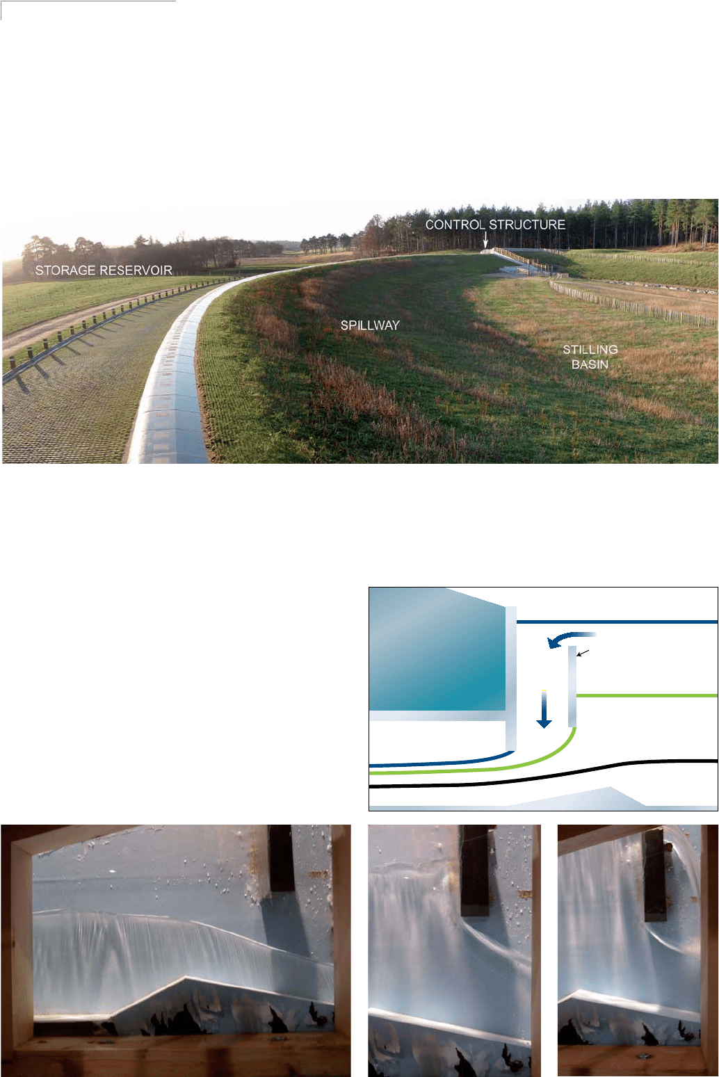
Figure 2 – Baffled crump weir concept & photographs from the physical model
Figure 1 – Chapelton Dam
WWW.WATERPOWERMAGAZINE.COM FEBRUARY 2010 43
FLOOD MANAGEMENT
flood risk from the Burn of Mosset at the 1 in 100 year return period.
Without investment in flood alleviation the flood damages in Forres
would exceed £43M (US$70M) over the next 50 years.
Moray flood alleviation was established in 2001 for the purpose
of delivering flood alleviation to a number of communities in Moray,
including Forres. It is an integrated team comprising The Moray
Council, Royal Haskoning, Morrison Construction and EC Harris.
The construction engineer under the Reservoirs Act for this scheme
was Ian Gowans.
THE SOLUTION
The Forres (Burn of Mosset) flood alleviation scheme comprises a flood
storage reservoir, situated on the Burn of Mosset at Chapelton, which
lies some 1.5km south of the town, combined with some minor flood
defences within the town of Forres and two small earthfill dams on the
periphery of the reservoir/storage area to avoid flooding of other prop-
erties. It is estimated to provide a standard of protection of at least 1 in
100 years, including an allowance for climate change up to 2080.
Work commenced on the scheme in 2002, with construction taking
place between November 2007 and November 2009.The flood stor-
age reservoir comprises:
U Earthfill embankment dam with a maximum height of 6.9m and a
crest length of about 200m.
U A 160m wide spillway, the upper part surfaced with open stone asphalt
and a permeable concrete slab construction at the toe of the spillway.
U A stilling basin, with the surface protected by two layers of
rock armour.
U A flow control structure incorporating a baffled crump weir, which
discharges up to 8.5m
3
/sec together with two penstock controlled
fixed orifices, for maintenance purposes (both closed under normal
operating conditions).
U A 3.8Mm
3
capacity flood storage reservoir.
Flows in excess of the capacity of the baffled crump weir are stored in the
reservoir until the inflow rate reduces and the retained water level reduces.
The spillway will allow the more extreme floods to be safely discharged
when the reservoir is full. The spillway is designed to pass the extreme
flood events required for this category A reservoir (PMF summer inflow
= 313m
3
/sec, 1 in 10,000 inflow = 163m
3
/sec) without damage.
BAFFLED CRUMP WEIR
The scheme was required to operate without user intervention, without
power and allow passage of migratory fish. A range of discharge control
mechanisms were reviewed during design, including a simple orifice, a
flume, and other control systems. However, to achieve a discharge of no
more than 8.5m
3
/sec, and to avoid flooding downstream over the range
of heads, it was decided to develop a baffled crump weir (BCW) device.
This would be along the lines of that described in a paper at the 13th
British Dams Society Biennial Conference in 2004, by Ackers et al [1].
The concept and optimised arrangement is diagrammatically illus-
trated in Figure 2. There are three main flow regimes: normal (low
flow), upstream baffle control and downstream baffle control. Physical
modelling [2] was used to determine the optimised geometry of the
baffled crump weir and the associated stage v discharge relationship.
The model tests also allowed the observation and measurement of flow
conditions in the culvert downstream of the control structure itself and to
assess the need for energy dissipation/tail water control measures. The per-
formance of the bypass sluices, which may be used if the control structure
were to block, or be shut off for maintenance purposes, was also tested.
These are controlled penstocks which remain closed under normal operat-
ing conditions. Should a blockage occur to the BCW during a flood event,
then one or other of the bypass controls may be operated.
Measurements and observations relating to the performance of the
crump weir for assessing the ability of migratory fish to pass over the
weir were also made.
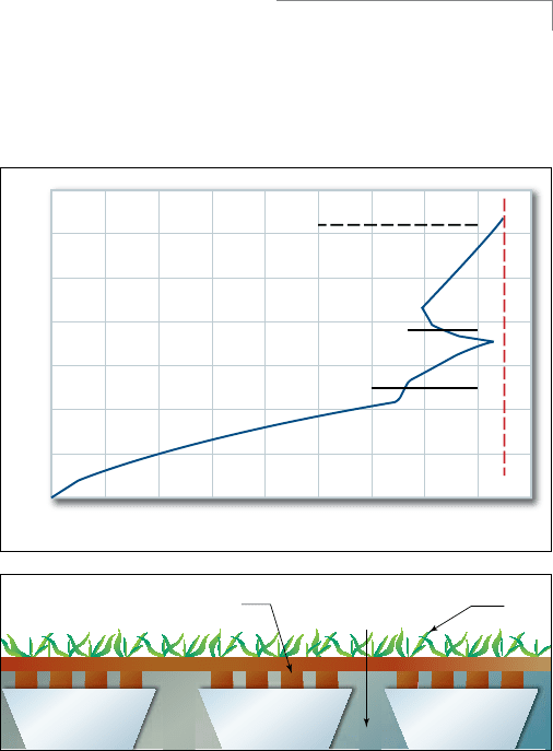
The optimised baffle arrangement, in the 1m wide channel, was
identified from the tests by achieving an acceptable stage/discharge
relationship. It consists of two vertical baffles, the downstream baffle
having an angled lip on its lower edge to ensure clean separation of
the flow from the structure. This is the first baffled crump weir flow
control structure constructed in a UK dam.
THE SPILLWAY
The spillway has a long curved crest that fits in well with the local topog-
raphy of the valley. This allows the PMF to discharge over the dam whilst
minimising the flood surcharge. During such events, water velocities on
the spillway will reach up to about 7m/sec for a period of up to 30 hrs.
It was deemed highly desirable to maintain the ‘green’ appearance
of the dam to blend in with the surrounding landscape. Therefore, the
design of the spillway and stilling basin combines hard engineering
beneath an aesthetically pleasing grass covering.
A number of options to reinforce the face of the spillway and still-
ing basin were considered. Open stone asphalt was considered the
best option for the upper slope of the spillway because it is relatively
flexible, accommodating minor settlement of the earth fill and can
easily be vegetated.
The factor of safety against sliding between the earth fill and the
spillway construction materials was critical. The most important fac-
tors being: the slope angle, the flow depth/velocity and the angle of
internal friction. In the final design the earth fill surface was benched
and covered with a needle punch geotextile. A 600mm layer of coarse
gravel was placed on the benched profile, covered with a 400mm
layer of open stone asphalt and topsoil [3].
A robust solution was required for the lower slope of the spillway
because of the higher water velocities and turbulence associated with
the hydraulic jump. A system involving a permeable concrete solu-
tion, with a ‘voided’ concrete slab on the surface was developed for
this area. This was constructed first along the toe and up the lower
part of the spillway slope. Then two layers of rock armour, infilled
with sand and gravel together with top soiling, was utilised to armour
the remainder of the horizontal and sloping areas around the periph-
ery of the stilling basin.
Open stone asphalt was utilised on the upper spillway slope. This is
the first large-scale use of open stone asphalt on a UK dam spillway.
Open stone asphalt is an inert material that does not deleteriously
7
6
4
3
2
1
0
0123456789
Discharge (m^3/s)
Reservoir level above crump weir crest (m)
Max design discharge rate 8.5 cumecs
Dam spillway crest level +30.7m ODN
Transition from upstream to downstream baffle control
Transition from crump weir to upstream control
Best fit line through test data
Upstream baffle control
Downstream baffle control
Void concrete slab with topsoil infill Grass
No-fines
concrete
“Normal”
concrete
Above, top: Figure 3 – Baffled crump weir stage vs discharge relationship
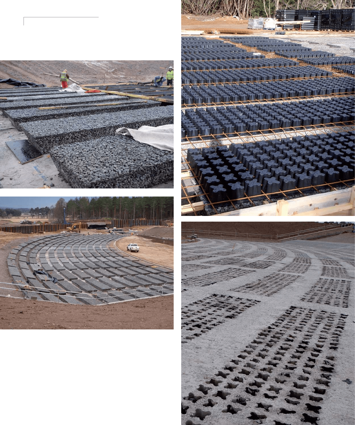
Above, bottom: Figure 4 – Construction of permeable concrete slab to spillway
44 FEBRUARY 2010 INTERNATIONAL WATER POWER & DAM CONSTRUCTION
FLOOD MANAGEMENT
affect water quality. It is also a permeable material with approximate-
ly 20% voids spread throughout the material. The irregular surface of
the open stone asphalt substrate allows the topsoil spread to interact
with it, thus reducing its susceptibility to creep down the slope. The
150mm soil cover also helps reduce the rate of degradation of the
hydrocarbon elements of the material by ultra-violet light.
The top soil covering the spillway and stilling basin will probably
be lost during any major overtopping event. But, given the infrequen-
cy of such events, the grass will probably be able to grow undisturbed
for many years.
BURN MANAGEMENT WORKS
The Burn management works are located upstream of the dam but
within the flood storage area. The main for this has been to create
an extensive natural sediment accretion zone with a large capacity
to store sands and gravels and retain large woody debris that will
require minimal ongoing management and little or no maintenance.
This thereby reduces the risk of sediment blockage of the dam con-
trol structure or damage from large woody debris, whilst work-
ing towards the objectives of the Water Framework Directive and
enhancing the ecological status of the watercourse.
The main body of the flood storage area comprises a wide flat area
of peat bog. The burn channel was confined on both sides through
this area by man-made embankments, which have been generated
over decades by dredging of the channel by the riparian owners, to
improve flow. This was necessitated by ongoing deposition of river
borne coarse sediments. Over virtually all of this length, the bed of the
burn was perched above the level of the surrounding floodplain.
The burn management works included channel realignment to
Above and right: Figure 4 – Construction of permeable concrete slab to spillway

WWW.WATERPOWERMAGAZINE.COM FEBRUARY 2010 45
FLOOD MANAGEMENT
restore more natural branched channels, wet woodland and bog
which are valuable habitats. To ensure that there was no interrup-
tion in passage for migratory fish, a shallow ‘secondary’ channel
was excavated on a sinuous alignment, between the two deliberate
breaches in the left bank of the burn. Under low flow conditions,
this initially permanently diverted about 20% of the flow in the
burn into the new channel across the adjacent floodplain. Areas
adjacent to the new channel were planted with native trees of local
provenance, whilst the lowest lying areas, that remained perma-
nently wet, were left open.
The Burn management works are an example of ecologically ben-
eficial long-term river restoration undertaken as an integral part of a
flood alleviation scheme.
The works will take a few years to fully develop and naturalise,
but already there is a noticeable increase in the amount of wildlife,
particularly wildfowl, and a major local geomorphological change.
Following a site visit shortly after the burn had been realigned, a
representative from Scottish Natural Heritage said ‘I was really
impressed to see this area of work and just how well the water is
spreading out across the area. The area provides a really good exam-
ple of…measures that can be taken to try and reconnect our rivers
with their floodplain.’ [4]
THE FIRST TEST
The Scheme was officially opened on 28 August 2009. One week
later 93mm of precipitation was recorded over a thirty-hour period
in the Burn of Mosset’s catchment. Despite a few key elements of the
scheme being not quite complete, the scheme successfully operated
and prevented flooding of hundreds of properties.
The community was obviously delighted to see the scheme avert
what would otherwise have been a significant flood. Positive feedback
has also been received from members of the local community regard-
ing the overall appearance of the project, which demonstrates the
successful integration of hard engineering with green landscaping.
During that event, a flow of 29m
3
/sec was measured at Wardend
Bridge, some 2km upstream of the dam site. Encouragingly, a signifi-
cant fan of sand and gravel was deposited onto the local flood plain.
It is beginning to operate as intended.
Ian Gowans, Reservoirs Act construction engineer;
Paul Winfield, Technical Director,
and Daniel Moysey, Senior Engineer, Royal Haskoning.
www.royalhaskoning.co.uk
The authors would like to thank:
The Moray Council for permission to publish this
paper; HR Wallingford for baffled crump weir physical
modelling; and Hesselberg Hydro for open stone
asphalt advice and construction
References
1. Ackers J, Hollinrake P, Harding R (2004). A passive flow-control device
for the Banbury flood storage reservoir. Proceedings of the 13th Biennial
Conference of the British Dam Society, Canterbury.
2. HR Wallingford, (2006).Report EX 5365, Chapelton Dam Control Structure.
3. Beiberstein A, Leguit N, Quesser J. Smith R ,(2004) Downstream Slope
Protection with Open Stone Asphalt, Proceedings of the biennial conference of
the British Dam Society, Canterbury, UK.
4. Quote regarding Burn Management Works, Scottish Natural Heritage, 13
November 2008.
IWP& DC
Left, top: Figure 5 – Laying of open stone asphalt to upper spillway area; Left,
bottom: Figure 6 – Burn Management Works

PROFESSIONAL DIRECTORY
46 FEBRUARY 2010 INTERNATIONAL WATER POWER & DAM CONSTRUCTION
CLASSIFIED
www.waterpowermagazine.com
MORE THAN 100 YEARS OF HYDROPOWER ENGINEERING
AND CONSTRUCTION MANAGEMENT EXPERIENCE
260 Dams and 60 Hydropower Plants (15,000 MW)
built in 70 countries
Water resources and hydroelectric development
• Public and private developers
• BOT and EPC projects
• New projects, upgrading and rehabilitation
• Sustainable development
with water transfer, hydropower, pumping stations
and dams.
COYNE ET BELLIER
9, allée des Barbanniers
92632 GENNEVILLIERS CEDEX - FRANCE
Tel: +33 1 41 85 03 69
Fax: +33 1 41 85 03 74
e.mail: commercial@coyne-et-bellier.fr
website: www.coyne-et-bellier.fr
COYNE ET BELLIER
Bureau d’Ingénieurs Conseils
www.coyne-et-bellier.fr
Over 40 years experience in Dams.
CFRD Specialist Design and Construction
●
Dam Safety Inspection
●
Construction Supervision
●
Instrumentation
●
RCC Dam Inspection
●
Panel Expert Works
Av. Giovanni Gronchi, 5445 sala 172, Sao Paulo –
Brazil
ZIP Code – 05724-003
Phone: +55-11-3744.8951
Fax: +55-11-3743.4256
Email: bayardo.materon@terra.com.br
ba_mater@yahoo.com.br
Lahmeyer International GmbH
Friedberger Strasse 173 · D-61118 Bad Vilbel, Germany
Tel.: +49 (6101) 55-1164 · Fax: +49 (6101) 55-1715
E-Mail: bernd.metzger@lahmeyer.de · http://www.lahmeyer.de
Your Partner for
Water Resources and
Hydroelectric Development
All Services for Complete Solutions
• from concept to completion and operation
• from projects to complex systems
• from local to multinational schemes
• for public and private developers
Norconsult AS
Vestfjordgaten 4,
1338 Sandvika, Norway
Tel: +47 67 57 10 00
Fax: +47 67 54 45 76
company@norconsult.com
Power and Water Management
Norconsult provides multidisciplinary
consultancy services within power
and water resources development.
www.norconsult.com
• River Basin Studies
• Underground Hydropower
• Dam Design
• Turbine Maintenance and
Optimisation
• Transmission and Distribution
• Environmental Impact Assessments
• Financial Engineering
• Power Utility Services
AF-Colenco Ltd
Täfernstrasse 26 • CH-5405 Baden/Switzerland
Phone +41 (0)56 483 12 12 • Fax +41 (0)56 483 17 99
colenco-info@afconsult.com • http://www.af-colenco.com
Consulting / Engineering and EPC Services for:
• Hydropower Plants
• Dams and Reservoirs
• Hydraulic Structures
• Hydraulic Steel Structures
• Geotechnics and Foundations
• Electrical / Mechanical Equipment
formerly Electrowatt-Ekono and Verbundplan
Hydropower and Water Management with
Worldwide Experience and Local Presence
For further information please contact
hp.energy@poyry.com and visit www.poyry.com
Construction and
refurbishment of small
and medium hydro
power plants.
.
turnkey / EPC plants
.
design & engineering
.
turbines
.
feasibility studies
.
operation services
.
financing
www.hydropol.cz
# (47) 67 53 15 06 in Norway
# (55) 11 3722 0889 in Brazil
E-mail: nickrbarton@hotmail.com
Website: http//www.qtbm.com
3
3
5
5
y
y
e
e
a
a
r
r
s
s
e
e
x
x
p
p
e
e
r
r
i
i
e
e
n
n
c
c
e
e
f
f
r
r
o
o
m
m
m
m
o
o
r
r
e
e
t
t
h
h
a
a
n
n
3
3
0
0
c
c
o
o
u
u
n
n
t
t
r
r
i
i
e
e
s
s
To advertise in the Professional
Directory or World Marketplace
section or for more information
contact Diane Stanbury on
tel: +44 (0)20 8269 7854
or email:
dianestanbury@globaltrademedia.com
Copy deadline for March 2010 issue
is 4 March 2010
INTERNATIONAL
& DAM CONSTRUCTION
Water Power

PROFESSIONAL DIRECTORY
WWW.WATERPOWERMAGAZINE.COM FEBRUARY 2010 47
CLASSIFIED
www.waterpowermagazine.com
Yolsu Engineering Services Ltd. Co.
Hürriyet Caddesi No:135 Dikmen, 06450 Ankara,TURKEY
Tel: +90 312 480 06 01 (pbx) Fax: +90 312 483 31 35
www.yolsu.com.tr info@yolsu.com.tr
Prefeasibilty, Feasibility,
Final & Detail Design,
Consulting Services:
• Basin development
• Dams and hydropower plants
• Irrigation and drainage
• Water supply and sewerage
• River engineering
• Highways and railways
Stellba Hydro AG Stellba Hydro GmbH & Co KG
Langgas 2 Badenbergstrasse 30
CH-5244 Birrhard D-89520 Heidenheim
Switzerland Germany
Telefon +41 (0)56 201 45 20 Telefon +49 (0)7321 96 92 0
Telefax +41 (0)56 201 45 21 Telefax +49 (0)7321 6 20 73
Internet www.stellba-hydro.ch Internet www.stellba.de
E-Mail info@stellba-hydro.ch E-Mail info@stellba.de
721
TENDERS
To advertise in the Professional
Directory or Wor ld Marketplace
section or for more information
contact Diane Stanbury on
tel: +44 (0)20 8269 7854
or email:
dianestanbury@globaltrademedia.com
Copy deadline for March 2010 issue
is 4 March 2010
INTERNATIONAL
& DAM CONSTRUCTION
Water Power
VISIT OUR WEBSITE
WWW.WATERPOWERMAGAZINE.COM
INTERNATIONAL
& DAM CONSTRUCTION
Water Power

WORLD MARKETPLACE
48 FEBRUARY 2010 INTERNATIONAL WATER POWER & DAM CONSTRUCTION
CLASSIFIED
www.waterpowermagazine.com
CYLINDERS
CRANES
GATES
GATES
HYDROMECHANIC AL
EQUIPMENT
• Custom Design Hydraulic Cylinders
• Servomotors
• Piston Accumulators'
• Hydraulic Power Units
• Control Panels
www.doucehydro.com
Douce Hydro FRANCE, USA and GERMANY
TelFrance:+33/322743108;E-mail:afleroy@doucehydro.com
TelUSA:+1/5865664725;E-mail:fvandenbulke@doucehydro.com
Tel Germany: + 49 / 177 398 37 78 ; E-mail : ublase-henke@doucehydro.com
BEARINGS
PAN
®
bronzes
and
PAN
®
-GF
self-lubricating bearings
Since 1931
- Superior quality with
• Highest wear resistance
• Low maintenance
• Or maintenance free
- Extended operating life
PAN-Metallgesellschaft
P.O. Box 102436 • D-68024 Mannheim / Germany
Phone: + 49 621 42 303-0 • Fax: + 49 621 42 303-33
kontakt@pan-metall.com • www.pan-metall.com
BEARING OIL COOLERS
HEXECO, Inc. ... aHeat Exchanger Engineering Co.
Tel: +1 (920) 361-3440 • Fax: +1 (920) 361-4554
E-Mail: info.wpd@hexeco.com • Web: www.hexeco.co
m
OIL COOLER
S
For
THRUST and
GUIDE
BEARINGS
CONCRETE COOLING
• COLD & ICE WATERPLANTS
• FLAKE ICE PLANTS
• ICE DELIVERY & WEIGHING SYSTEMS
• ICE STORAGES
KTI-Plersch Kältetechnik GmbH
Carl-Otto-Weg 14/2
88481 Balzheim
Germany
Tel:/Phone: +49 - 7347 - 95 72 - 0
Fax: +49 - 7347 - 95 72 - 22
Email: ice@kti-plersch.com
Website: www.kti-plersch.com
CONCRETE COOLING
FILTRATION EQUIPMENT
WWW.WATERPOWERMAGAZINE.COM
kuenzamerica@kuenz.com
www.kuenzamerica.com
TRASH RAKE CLEANING
POWER HOUSE CRANES
America Inc.
kuenzamerica@kuenz.com
www.kuenzamerica.com
TRASH RAKE CLEANING
POWER HOUSE CRANES
America Inc.
CIVIL ENGINEERING:
U Þ`iÀÃ] «ÜiÀ ÕÌÃ >` VÌÀÃ
vÀ `> }>ÌiÃ] ëÜ>Þ }>ÌiÃ]
Ì>i }>ÌiÃ] ÃÕVi }>ÌiÃ
U }iiÀ}] ÃÌ>>Ì >` V
ÃÃ} v V«iÌi Þ`À>ÕV
>` iiVÌÀV ÃÞÃÌià vÀ `> }>Ìi
«iÀ>Ì Õ« Ì >ÕÌ>ÌV ÀiÃiÀÛÀ
ÌÀ} >` VÌÀ ,®
www.montanhydraulik.com
Providing water control solutions through thoughtful engineering,
innovative design, attention to detail and outstanding customer
service. Contact us for inflatable water control gates and rubber
dams.
PO Box 668, Fort Collins, CO 80522 USA
Tel: 970-568-9844
www.obermeyerhydro.com
HYDRO CASTINGS
• Water turbine components
• Castings from 100 kg to 30 tons
• Latest CAD-CAM capabilities
• Certified Quality Assurance ISO 9001
• Environmental Management System ISO14001
Your contact: Mr. Timo Norvasto, Sales Manager
Lokomo Steel Foundry
Tel: +358 204 84 4222
Fax: +358 204 84 4233
Email: timo.norvasto@metso.com
Web: www.metsofoundries.com

WORLD MARKETPLACE
WWW.WATERPOWERMAGAZINE.COM FEBRUARY 2010 49
CLASSIFIED
www.waterpowermagazine.com
HYDROMECHANIC AL
EQUIPMENT
HYDRO POWER
PLANT EQUIPMENT
HYDRO POWER
PLANT EQUIPMENT
HYDRO POWER
PLANT EQUIPMENT
ANDRITZ HYDRO GmbH
Penzinger Strasse 76, A-1141 Vienna, Austria
Phone: +43 (1) 89100-0, Fax: +43 (1) 8946046
contact-hydro@andritz.com • www.andritz.com
Your Partner
for renewable and clean energy
We focus on the best solution – from water to wire.
Voith Hydro Holding GmbH & Co. KG
Alexanderstrasse 11
89522 Heidenheim/Germany
www.voithhydro.com
A Voith and Siemens Company
䡲 Water power plant equipment
(electrical and mechanical)
䡲 Pumps
䡲 Governors
䡲 Automation
䡲 Modernization of existing power plants
䡲 Hydro power services
䡲 Ocean energies
INSTRUMENTATION
(DAM MONITORING)
Vikas Kothari: Executive Director Tel: 91 11 29565552 TO 55
Om Metals Infraprojects Ltd. Fax: 91 11 29565551
4th Floor, NBCC Plaza, Mobile: 91 98110 68101
Tower III, Sector 5, Email: vikas@ommetals.com
Pushp Vihar, info@ommetals.com
Saket, New Delhi, 110 017, INDIA Web: www.ommetals.com
Turnkey EPC contracts for:
•
Radial Gates •Trash Racks & TRCM
•V ertical Gates •Gantry Cranes & EOT
•Penstocks •Mechanical/ Hydraulic Hoists
•Stoplogs •Draft Tubes
Turnkey EPC contracts for:
•Radial Gates •Trash Racks & TRCM
•V ertical Gates •Gantry Cranes & EOT
•Penstocks •Mechanical/ Hydraulic Hoists
•Stoplogs •Draft Tubes
Om Metals
Reliable and innovative solutions utilizing
over 156 years continuos hydro-electric
experience.
Fully customised supply of turbines,
generators, controls, switchgear &
associated plant up to around 20MW,
including a micro hydro range of turbines.
Japan: Gilbert Gilkes & Gordon Ltd
h-yamamo@rf6.so-net.ne.jp
North America:
Vancouver Island Technology Park
2103 - 4464 Markham Street
Victoria BC V8Z 7X8
b.sellars@gilkes.com
t: 250-483-3883
UK: Gilbert Gilkes & Gordon Ltd,
Canal head North, Kendal,
Cumbria LA9 7BZ
[ M
hydro@gilkes.com
N World wide referenced water to wire General Contractor
N Turbines and Generators
N Electromechanical Equipment
N Switchgears
N Control Protection Monitoring and SCADA Systems
N Balance of the Plant
N Turn key projects
N Rehabilitation
S.T.E. S.p.a. - Via Sorio, 120 - 35141, PADOVA(Italy)
tel. +39 049 2963900 - fax. +39 049 2963901
Email: ste@ste-energy.com Web: www.ste-energy.com
ISO 9001 CERTIFIED
Geokon, Incorporated manufactures a full range
of geotechnical instrumentation suitable for
monitoring dams. Geokon instrumentation employs
vibrating wire technology that provides measurable
advantages and proven long-term stability.
The World Leader in
Vibrating Wire Technology
TM
Geokon, Incorporated
48 Spencer Street
Lebanon, New Hampshire
03766
•
USA
Dam Monitoring Instrumentation
1
•
603
•
448
•
1562
1
•
603
•
448
•
3216
info@geokon.com
www.geokon.com
Contact Diane Stanbury on:
+44 208 269 7854
dianestanbury@
globaltrademedia.com
For World Marketplace
advertising opportunities

WORLD MARKETPLACE
50 FEBRUARY 2010 INTERNATIONAL WATER POWER & DAM CONSTRUCTION
CLASSIFIED
www.waterpowermagazine.com
SMALL HYDROELECTRIC
POWER SETS
SMALL HYDROELECTRIC
POWER SETS
MICRO/SMALL
HYDROELECTRIC POWER SETS
INSTRUMENTATION
(GEOTECHNICAL)
SCREENING
Planning a run-of-river project?
Reduce your capital costs signicantly!
Why a coanda intake?
● Eliminates desander
● Protects your investment
from premature wear
and debris.
● Flows up to 25 M3/sec.
● Screens out debris
down to 0.5mm
● Customizable for
a range of conditions
● MAXIMIZES POWER
GENERATION
Partial Discharge?
www.pdix.com
PARTIAL DISCHARGE DETECTION
INSTRUMENTATION
(DAM MONITORING)
Contact Diane Stanbury on:
+44 208 269 7854
dianestanbury@
globaltrademedia.com
For World Marketplace
advertising opportunities
+43 - 7234 - 83 902
Dam Safety Instrumentation • Fiber Optic and
Vibrating Wire Technologies • In-Situ Testing
and Turn-Key Solutions
• Piezometers
• Pressure Cells
• Extensometers
• Crackmeters
• Inclinometers
• Tiltmeters
1-877-ROCTEST
info@roctest.com
• www.roctest.com
33.1.64.06.40.80
info@telemac.fr
• www.telemac.fr