Woodyard D. (ed.) Pounders Marine diesel engines and Gas Turbines
Подождите немного. Документ загружается.

with thermostatic valves, continuously regulate cooling water temperature to
achieve the optimized operating condition. Because charge air from the turbo-
charger never falls below the dew point, there is no danger of water condensa-
tion in the cylinders.
The cooling water system comprises an LT system and an HT system, each
cooled by freshwater. The LT circuit is used to cool charge air and lubricat-
ing oil. The HT circuit cools the cylinder liners and heads, fostering optimized
combustion conditions, limiting thermal load under high load conditions, and
preventing hot corrosion in the combustion area. Under low load, the system is
designed to ensure that the temperature is high enough for efficient combustion
and that cold corrosion is avoided.
Water in the LT system passes through the LT circulating pump which
drives the water through the second stage of the charge-air cooler and then
through the lubricating oil cooler before the water leaves the engine together
with the HT water. The amount of water passing through the second stage
of the charge-air cooler is controlled by a three-way valve dependent on the
charge-air pressure. If the engine is operating at low load condition the tem-
perature regulation valve cuts off the LT water flow, thus securing preheating
of the combustion air by the HT water circuit in the first stage.
The HT cooling water passes through the HT circulating pump and then
through the first stage of the charge-air cooler before entering the cooling water
jacket and the cylinder head. It then leaves the engine with the LT water. Both
LT and HT water leave the engine via separate three-way thermostatic valves
that control the water temperature.
All moving parts of the engine are lubricated with oil circulating under
pressure, the system served by a lubricating oil pump of the helical gear type.
A pressure control valve built into the system reduces the pressure before the
filter with a signal taken after the filter to ensure constant oil pressure with
dirty filters. The pump draws oil from the sump in the base frame, the pres-
surized oil then passing through the lubricating oil cooler and the filter. The oil
pump, cooler and filter are all located in the front box. The system can also be
provided with a centrifugal filter. Lubricating oil cooling is carried out by the
LT cooling water system, with temperature regulation effected by a thermo-
static three-way valve on the oil side (see earlier). The engine is equipped as
standard with an electrically driven pre-lubricating pump.
The L16/24 engine is prepared for MAN Diesel’s CoCoS computerized sur-
veillance system, a Microsoft Windows–based program undertaking fully inte-
grated monitoring of engine operation, maintenance planning, and the control and
ordering of spares. The four CoCoS software modules cover engine diagnosis,
maintenance planning, spare parts catalogue, and stock and ordering.
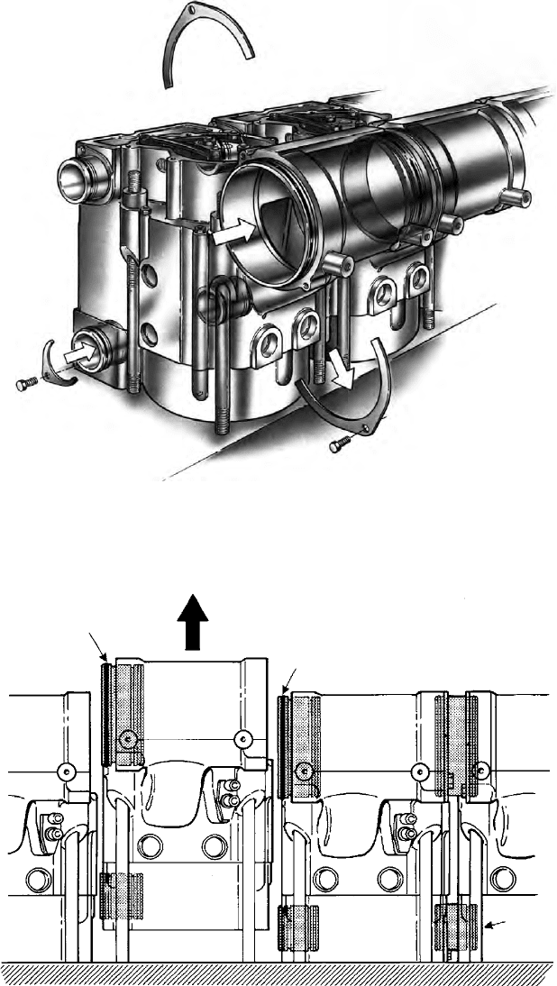
Each cylinder assembly (head, piston, liner and connecting rod) can be
removed as a complete unit for repair, overhaul or replacement by a renovated
unit onboard or ashore. Replacing a cylinder unit (Figures 30.11, 30.12 and
30.13) is accomplished by removing the covers and HP fuel injection pipe, and
disconnecting a snap-on coupling to the exhaust gas pipe. The only cooling
man (Holeby) 781
782 High-Speed Engines
FigurE 30.11 man l16/24 engine: preparing for cylinder unit removal
Bushes for charge
air and cooling
water are pushed
to the right
Removal of
cylinder unit
O-ring
Cyl.
unit 1
Cyl. unit 2
Cyl. unit 3 Cyl. unit 4
Cooling
water
connections
FigurE 30.12 man l16/24 engine: preparing for cylinder unit removal
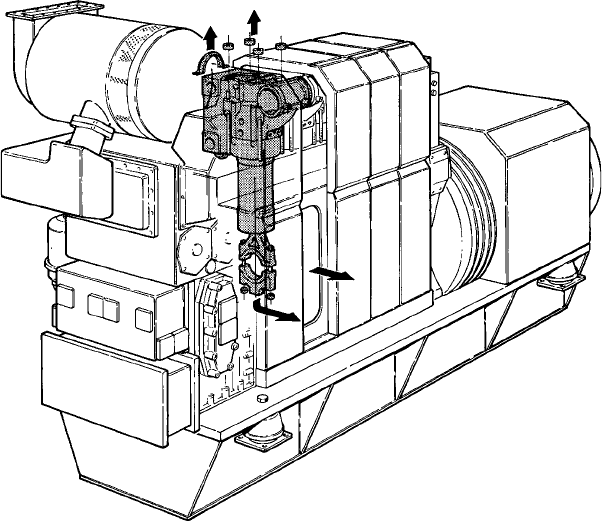
water connections are to the cylinder unit as there is no cooling water in the
base frame. Inlet and outlet cooling water passes between cylinder units via
bushes which are pushed aside in disassembling a unit. The charge-air connec-
tions are dismounted in the same way. The four hydraulically fastened cylinder
head nuts and the two connecting rod nuts (all six are of the same size) are then
removed, allowing the 200 kg unit to be withdrawn from the engine.
The design principles of the L16/24 engine were later applied to the larger
L27/38 and L21/31 medium-speed engines, respectively introduced in 1997
and 2000 for both genset and propulsion applications (see Chapter 22).
mitSuBiSHi
Fast ferry propulsion business potential stimulated the development in the
early 1990s of the Mitsubishi S16R-S high-speed engine by the Japanese
group’s Sagamihara Machinery Works. The higher-performance V16-cylinder
model was evolved from the established S16R design which had been in pro-
duction since 1989 as a general purpose marine engine. A constant pressure
turbocharging system based on a newly developed turbocharger and a revised
fuel injection system contributed to a 20 per cent rise in the power output.
The 170 mm bore/180 mm stroke design has a maximum continuous rating of
2100 kW at 2000 rev/min with overload ratings up to 2300 kW.
mitsubishi 783
FigurE 30.13 man l16/24 engine: removing a complete cylinder unit
784 High-Speed Engines
The weight was reduced to 89 per cent of the original engine, primarily
through the adoption of aluminium alloy components optimized in size for
the duty. An overall weight of 5500 kg underwrites a power-to-weight ratio of
2.62 kg/kW.
motorEn- unD turBinEn-union
A portfolio of high-performance high-speed designs with an upper output limit
of 9100 kW is offered by MTU (Motoren- und Turbinen-Union) of Germany,
which was created in 1969 when Daimler-Benz and MAN consolidated the
development and production of relevant engines from MAN and Maybach
Mercedes-Benz. MTU Friedrichshafen became part of the Deutsche Aerospace
group in 1989 and subsequently a DaimlerChrysler company before coming
under the umbrella of the Tognum Group in 2006.
Series 396
Addressing lower power demands, MTU’s Series 396 engine is long established as
a propulsion and genset drive, the 165 mm bore/185 mm stroke design delivering
up to 2560 kW at 2100 rev/min from V90° configuration 8-, 12- and 16-cylinder
models (Figure 30.14). Engines are available in three different versions:
l TB04, with external charge-air cooling (intercooler in raw water circuit).
l TC04, with internal charge-air cooling (intercooler in engine coolant circuit).
l TE04, with internal charge-air cooling (intercooler in engine coolant
circuit; split-circuit coolant system).
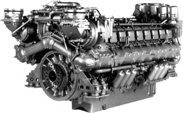
TE split-circuit cooling system: the Series 396 engine—and other MTU
designs—can be supplied with the TE split-circuit coolant system with a
power-dependent sub-circuit to cool the combustion air. Optimum performance
FigurE 30.14 mtu 16v 396 tE94 engine with split-circuit cooling system
is fostered throughout the engine’s power range: at idling speed the air sup-
ply is heated to achieve complete fuel combustion; in the medium power and
full load range conditions are optimized for high output while keeping thermal
stress on engine components at a low level.
Coolant flow from the engine is split in two. Approximately two-thirds
of the flow pass through a HT circuit and returns directly to the engine inlet,
while the remainder is fed into a thermostatically controlled LT circuit. During
engine idling or low load operation the thermostat allows heated coolant to
bypass the recooler on its way to the intercooler in order to warm up the com-
bustion air and prevent white smoke in the exhaust.
An annular slide valve in the thermostat remains in its initial position until
increasing power raises the coolant temperature, causing the wax pellet in the
thermostat to expand. Gradual closing of the bypass line now directs the cool-
ant stream through the recooler. As a result, coolant entering the intercooler is
at a low temperature which, in turn, underwrites a high-combustion air volume
and, consequently, maximum engine power. After flowing through the inter-
cooler and the oil heat exchanger, ‘cold’ coolant rejoins the uncooled HT cir-
cuit, thereby cooling the total volume flow before it re-enters the engine.
Sequential turbocharging is exploited for propulsion engines required to
deliver high power in the lower- and medium-speed ranges. The system incor-
porates two or three turbochargers with automatic on/off control as a function
of engine speed, power demand and turbocharger maximum efficiency. In addi-
tion to increased torque the system yields reduced fuel consumption and lower
exhaust temperatures.
Cylinder cut-out (no fuel injection into selected cylinders) is adopted for
engines operating under varying speed conditions (low idling speed). The
system enhances combustion at idle, thus shortening the warm-up phase and
avoiding white smoke from unburnt fuel, and generally contributing signifi-
cantly to environmental compatibility.
Series 595
A power range from 2000 kW to 4320 kW at 1500–1800 rev/min is covered by
the 190 mm bore/210 mm stroke Series 595 engine, introduced in 1990 in V12-
and V16-cylinder versions for propulsion and genset applications (Figure 30.15).
Contributing to a compact design yielding power-to-weight ratios of under
3 kg/kW and a power-to-space ratio of 250 kW/m
3
(including all ancillaries)
are the following features: a V72° cylinder configuration with all ancillaries
arranged for space saving within the engine contour; nodular cast iron crank-
case extending below the crankshaft centreline to maximize rigidity; crankshaft
with hardened main and connecting rod bearing radii, designed to withstand
firing pressures of up to 180 bar; individual fuel injection pumps designed for
injection pressures of up to 1500 bar; plate-type coolant heat exchanger inte-
grated with the engine; split-circuit coolant system; and two-stage sequential
turbocharging system with charge-air cooling for boost pressures of up to
4.8 bar. The turbocharging sequencing is electronically controlled.
motoren- und turbinen-union 785
786 High-Speed Engines
Components requiring regular servicing are located to provide good access
at the engine’s auxiliary power take-off end. Maintenance is also smoothed by
the modular arrangement of functionally interlinked components, plug-in con-
nections and the omission of complex pipework, hose couplings and cabling. A
new ECS was purpose-developed by MTU for the Series 595 engine to provide
information for the operator, promote easier operation and enhance safety, reli-
ability and economy. The safety functions embrace engine and plant monitor-
ing, overload protection, diagnostics, automatic start-up and load control.
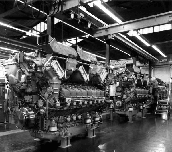
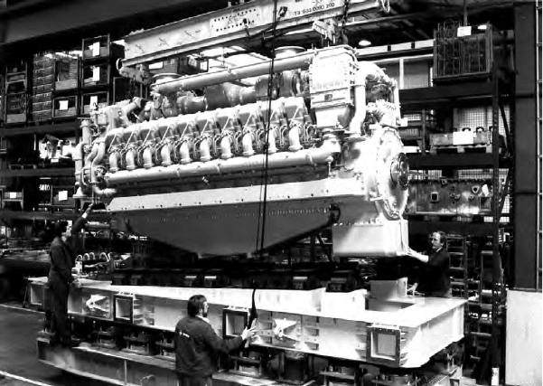
Series 1163
The highest power outputs from the MTU programme were offered for many
years by the Series 1163 ‘frigate’ engine (Figure 30.16). The 230 mm bore/
280 mm stroke design is produced in V60° configuration 12-, 16- and 20-cylinder
versions delivering up to 7400 kW at 1300 rev/min for commercial and naval
propulsion installations. The key elements of the design are summarized as
follows.
Crankcase: nodular cast iron structure with access ports on both sides and
a flange-mounting facility for alternators or other driven machinery; a welded
sheet steel oil pan is provided.
Cylinder liner: replaceable, wet-type centrifugally cast.
FigurE 30.15 v16-cylinder mtu Series 595 engine
Cylinder head: cast iron component arranged with two inlet and two exhaust
valves, all equipped with Rotocap rotators, a centrally located fuel injector sepa-
rated from the rocker area, and a decompression valve.
Valve actuation: by two camshafts, roller tappets, pushrods and rocker
arms. Valve clearance adjustment is performed via two screws located in the
rocker arms.
Crankshaft: a single-structure forged component finished all over and fea-
turing bolted-on counterweights; axial crankshaft alignment is effected by a
deep-groove ball bearing.
Bearings: thin-walled, two-piece, replaceable steel-backed tri-metal sleeve
bearings for the crankshaft and connecting rod, with cross-bolted bearing caps.
Connecting rods: forged and finished all over and grouped in pairs to serve
two opposite cylinders.
Piston: composite-type with light alloy skirt and bolted-on steel crown,
cooled by oil spray nozzles; three compression rings are fitted in the crown,
with one oil control ring between crown and skirt; all rings replaceable after
piston crown removal.
Fuel injection: direct injection by individual pumps and via short HP lines;
pump replacement requires no readjustment; gear-type fuel delivery pump; two
duplex fuel filters; cylinder cut-out facility available (see section Series 396
Engine).
Governor: hydraulic MTU unit mounted on the gearcase, with the linkage
between governor and fuel injection pumps accommodated in the gearcase and
camshaft space. Engine shutdown solenoids act on the fuel rack; in addition, inde-
pendent emergency air shut-off flaps are arranged to block the engine’s air supply.
motoren- und turbinen-union 787
FigurE 30.16 mtu Series 1163 engine in v20-cylinder form
788 High-Speed Engines
Lubricating oil system: self-contained forced feed system, with oil flow pro-
gressing through gear-type pumps, heat exchanger and filters to the engine lubri-
cation points. Oil for piston cooling is tapped off after the heat exchanger and
filters; the engine-mounted oil heat exchanger is integrated in the engine coolant
circuit (Series 1163-02 model) or raw water circuit (Series 1163-03 model).
Cooling system: two-circuit system; closed engine coolant circuit using two
centrifugal pumps; thermostatic control; recooling provided by raw water heat
exchanger or fan cooler.
Turbocharging: the Series 1163-02 model exploits pulse charging based on
two turbochargers (one turbocharger for the 12-cylinder engine) with intercool-
ers incorporated in the raw water circuit. The Series 1163-03 model exploits
constant pressure turbocharging with two-stage air compression and interstage
cooling; four or five charger groups (depending on the application) are under
sequential turbocharging control; the constant pressure exhaust manifold is
located in the V-bank, and charge-air pipework mounted externally; high- and
low-pressure intercoolers are incorporated in the raw water circuit. For start-
up and low load operation the Series 1163-03 model features a charge-air
preheater, fed with engine coolant, in each HP intercooler outlet. Coolant jack-
ets for the exhaust manifolds and turbocharger turbines of this model secure
reduced heat rejection.
Like the Series 595 engine, the Series 1163 design features inboard HP
fuel injection lines and the enclosure of all hot exhaust components in water-
cooled and gas-tight casings: valued for unmanned enginerooms by helping to
reduce the possibility of fire in the event of fuel or lubricating oil leakages. A
triple-walled insulation design also maintains surface temperatures well within
the limit of 220°C dictated by classification societies, as well as considerably
reducing radiant heat in the engineroom.
Sequential turbocharging (output-dependent control of the number of tur-
bochargers deployed) fosters high torque at low revolutions per minute (wide
performance band) and hence good acceleration. Optimization during sea tri-
als, with assistance from an ECS, can eliminate black smoke emissions.
An uprated Series 1163 engine for fast ferry propulsion benefits from:
l An improved fuel injection system to optimize consumption and exhaust
emissions reduction.
l A higher cylinder head fatigue strength, thanks partly to bore cooling.
l Improved power and torque characteristics achieved by modifying the
two-stage sequential turbocharging system.
l Adaptation and optimization of the turbochargers to match the increased
cylinder output (325 kW).
l Intelligent electronic engine management.
Series 8000 Engine
MTU’s thrust in commercial and naval propulsion sectors was strengthened
in 2000 with the introduction of its most powerful engine ever designed, the
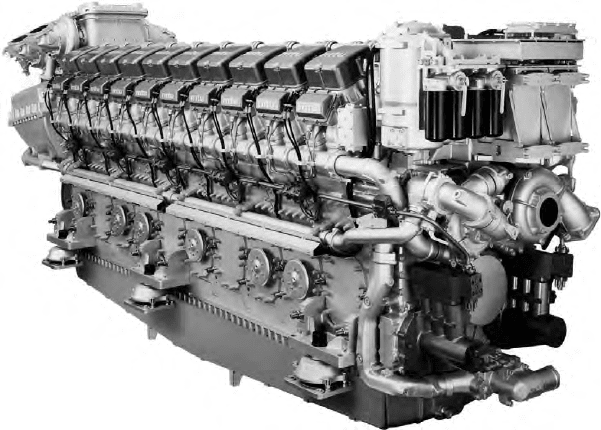
advanced 265 mm bore Series 8000 design (Figure 30.17). Innovative fuel
injection, turbocharging and electronic management systems proven on earlier
MTU engines are exploited, while a new modular power unit-based structure
helps to ease maintenance and minimize life-cycle costs.
The Series 8000 engine was conceived with the aim of consolidating the
company’s position in the market for fast ferries and extending opportunities to
mainstream commercial arenas, such as cruise liners. Outputs up to 9100 kW for
naval vessels and mega yachts were initially sanctioned from the V20-cylinder
model which launched the series, with an 8200 kW rating at 1150 rev/min ap-
proved for high-speed commercial tonnage. A potential for firing pressures up
to 230 bar underwrites future power rises, projected after successful long-term
testing of engines in service. The first four production 20V 8000 engines were
installed as a mega-yacht propulsion plant, subsequent orders calling for units
to power a large catamaran fast ferry, frigates and naval supply vessels.
A V48° cylinder configuration contributes to a narrow engine (1.9 m wide),
well suited for fast catamaran and monohull ferries where machinery space
is at a premium. The specific power output related to volume and weight is
reflected in figures of 200 kW/m
3
and just over or under 5 kg/kW, depending on
the application.
Common rail fuel injection, proven on MTU’s 1996-launched 165 mm bore
Series 4000 engine, allows all injection parameters affecting combustion to be
independently controlled; these include such variables as the timing, period
and pattern of injection as well as the injection pressure. Independent control
fosters reduced fuel consumption and exhaust emission levels across the entire
motoren- und turbinen-union 789
FigurE 30.17 mtu Series 8000 engine in v20-cylinder form. note the fuel pumps
(lower right) for the common rail injection system
790 High-Speed Engines
engine power curve. The common rail system also benefits engine noise and
vibration levels, substantially lowering them at idling and mid-range running
speeds compared with conventional systems.
Two HP fuel pumps mounted at the free end of the engine develop pressure
levels of up to 1800 bar. The fuel is pumped through double-walled delivery
lines arranged longitudinally down the engine and directed to the cylinders via
distributors into individual accumulators. The accumulators are large enough
to prevent any drop in pressure before the fuel injector when maximum fuel
quantities are being injected, and to prevent pressure oscillations in the system.
The fuel is injected via electronically controlled injectors arranged centrally in
the cylinder head.
Experience gained from numerous Series 4000 engines in service moulded
the common rail system created by L’Orange for the new larger engine, which
is detailed in Chapter 8. Considerable scope for further development of the
system promised further advances in fuel economy, emission levels and noise
reduction in future production engines.
The Series 8000 design’s sequential turbocharging system had been suc-
cessfully applied by MTU to its Series 396, 538, 595 and 1163 engines for
many years to secure a large performance map width. First fitted on production
models in 1982, the system marries a series of individual turbochargers that can
be switched-in and -out while the engine is running to match the load. High-
brake mean effective pressures can thus be sustained even at low engine speeds.
Among the merits cited for the sequential turbocharging system are excellent
acceleration and substantially lower fuel consumption and smoke emission levels
at low- and medium-power rates. Additionally, in twin-engine plants with com-
mon transmission and fixed pitch propellers or waterjets, the system can be run
on one engine virtually up to its rated power. Quadruple MTU ZR 265 turbo-
chargers are specified for the single-stage turbocharging system serving the
20V 8000 engine (Figure 30.18).
Both common rail fuel injection and sequential turbocharging systems con-
tribute to a claimed specific fuel consumption of below 195 g/kW h across a
broad power range, and less than 190 g/kW h at the most economical points.
These figures are achieved while maintaining NOx emissions within IMO lim-
its. Smoke indices are reportedly 0.4 Bosch throughout the entire engine per-
formance map and 0.2 Bosch at full load.
Electronics are increasingly exploited by engine designers, MTU address-
ing the full potential from the conceptual stage of the Series 8000. The result-
ing MDEC (MTU Diesel Engine Control) engine management system allows
all functions and parameters to be precisely monitored and controlled for opti-
mum effect. The system also incorporates the basic functions for trend analysis
and diagnostics, and the facility for integrating the engine in a comprehensive
control and monitoring package for the entire propulsion system as well as
other ship systems. MTU offers these advanced options in the shape of its RCS
(remote control system) and MCS (monitoring and control system) products.