Xin Q. Diesel Engine System Design
Подождите немного. Документ загружается.


© Woodhead Publishing Limited, 2011
348
5
Engine–vehicle matching analysis in diesel
powertrain system design
Abstract: This chapter discusses vehicle powertrain performance and the
impact on diesel engine system design in ring operation. It begins by
summarizing the formulae of vehicle performance analysis, followed by
analytical engine–vehicle matching methods with engine characteristic
maps for optimum fuel economy and drivability. It then describes the
transient powertrain performance simulations of vehicle driving cycles and
acceleration. It emphasizes the concept of ‘top–down’ powertrain design
approach to optimize the interface between the vehicle and the engine.
Hybrid powertrain performance analysis is also briey introduced.
Key words: vehicle performance, drivetrain, powertrain dynamics,
engine–vehicle matching, driving cycle, fuel economy, drivability, transient
performance, hybrid.
5.1 The theory of vehicle performance analysis
5.1.1 Introduction of vehicle analysis areas
Automotive engines are designed for real-world vehicle operating needs.
Engine development is focused on improving engine cycle processes and
torque curve shape. At the same time, it strives to reduce parasitic losses
and fuel consumption. Drivetrain design is focused on increasing drivetrain
efciency, reducing resistance forces, and selecting proper transmission
ratios to match the engine. Engine–vehicle system integration for the diesel
powertrain requires a close collaboration between the two. Among the
four major areas of vehicle dynamics (powertrain transmission, braking,
suspension, and steering systems), the rst two areas are directly related to
engine system design.
The following topics are important in vehicle performance analysis for
engine system design: longitudinal dynamics and vehicle force distribution,
tire–road rolling resistance, aerodynamic drag resistance, vehicle inertia force,
transmission and torque converter modeling, vehicle acceleration calculation,
and vehicle fuel economy calculation.
Heavy-duty vehicle drivetrain design fundamentals are introduced in
Jones (1991). Powertrain design process is discussed by Dopson et al. (1995)
and Ferraz et al. (2001). Vehicle powertrain simulation methodologies are
presented by Morel et al. (1999), Ciesla et al. (2000), and Guzzella and
Diesel-Xin-05.indd 348 5/5/11 11:49:13 AM
349Engine–vehicle matching in diesel powertrain system design
© Woodhead Publishing Limited, 2011
Sciarretta (2005). Heavy-duty vehicle test cycles are investigated by Bata
et al. (1994) and Clark et al. (2003). The coastdown method is discussed
by Petrushov (1997) and Miller (2004). Overviews on vehicle fuel economy
are provided by Ehlbeck and Mayenburg (1991), Simner (1996), Patton et
al. (2002) and Sovran and Blaser (2003). Transmission efciency has been
researched by Kluger and Greenbaum (1993). Torque converter design and
performance are reviewed by Mercure (1979). The SAE procedures listed
in the section of references at the end of this chapter also provide valuable
fundamental information on vehicle, powertrain and drivetrain.
5.1.2 Formulae of vehicle performance analysis
Heavy-duty trucks are usually front-engined and rear-wheel-driven in order to
obtain effective engine cooling and better tractive force during acceleration and
upgrade climbing. In order for a vehicle to move, the tractive force provided
by the engine and the transmission needs to be greater than the total of all
static resistance forces. However, the maximum tractive force acting on the
vehicle driving wheels is limited by the tire–road adhesion force, even if the
engine and the transmission can produce a higher tractive force.
The vehicle force balance at any steady-state or transient condition can
be written as
F
t
+ F
er
+ F
acc
+ F
br
+ F
rf
+ F
a
+ F
i
+ F
gl
+ F
dr
= 0 5.1
When the vehicle moves at a constant speed, the inertia force F
i
= 0. If F
i
is
not equal to zero, the vehicle either accelerates or decelerates in transients.
F
t
is the tractive force acting on the vehicle wheels and is delivered from
engine ring operation. Note that the tractive force due to engine ring is
dened as a positive value, and all resistance forces are dened as negative
values. During engine ring, the engine brake retarding force F
er
= 0. F
acc
is a vehicle equivalent resistance force acting on the wheels and caused
by accessory loads such as the cooling fan, the air conditioning and the
power steering. If the driver does not use the service brake (wheel brake),
the service brake force F
br
= 0. F
rf
is the tire–road rolling friction force. F
a
is the aerodynamic resistance force. F
gl
is the gravity force on a gradient.
F
dr
is the resistance force of drivetrain retarders such as the hydrodynamic
or electromagnetic retarder. During engine ring without wheel braking or
drivetrain retarder braking, the tractive force acting on the vehicle wheels
is given by
F
t
= – (F
acc
+ F
rf
+ F
a
+ F
i
+ F
gl
). 5.2
On the other hand, the maximum allowable tractive force is limited by the
tire–road adhesion force, which is equal to the normal load multiplied by
the road adhesion coefcient. The adhesion force is determined by the axle
Diesel-Xin-05.indd 349 5/5/11 11:49:13 AM
350 Diesel engine system design
© Woodhead Publishing Limited, 2011
load, the road surface condition and the tires. For example, an icy road has
a very low adhesion force, and the vehicle wheels may slip on the ice. It
should be noted that each term in the vehicle force balance equation 5.1 is
for the total vehicle mass m
v
(including trailers, if any).
The gravity force is given by F
gl
= m
v
g sin q, and the road grade is de ned
as G
r
= tan q, where q is the road slope angle (positive for downhill, negative
for uphill), and g is the acceleration due to gravity. The rolling friction
resistance is calculated by F
rf
= – m
v
g · f
rf
cos q if the aerodynamic lift force
is ignored in the net normal load. The tire rolling friction coef cient f
rf
increases when the vehicle speed, the tractive force, or the tire tilting angle
increases. The friction coef cient decreases when the tire pressure or the tire
temperature increases. The tire rolling friction coef cient is also affected by
tire structure, tire material and road surface condition. The friction coef cient
is independent of the vertical load. Usually, the rolling friction coef cient
values are between 0.005 and 0.01 on a concrete road surface. Moreover,
for a radial-ply truck tire, when N
v
< 100 km/hour, previous experimental
data gave f
rf
= 0.006 + 0.23(0.001N
v
)
2
, where N
v
is vehicle speed; and for
a bias-ply truck tire, f
rf
= 0.007 + 0.45(0.001N
v
)
2
(Wong, 1993).
The aerodynamic resistance force is calculated by
Ff
AN
Ff
aA
Ff
Ff
MB
Ff
av
Ff
av
Ff
AN
av
AN
vw
Ff= – Ff
Ff
aA
Ff= – Ff
aA
Ff
,
05
Ff05Ff
Ff
aA
Ff05Ff
aA
Ff
2
Ff
aA
Ff.Ff
aA
Ff
Ff
aA
Ff05Ff
aA
Ff.Ff
aA
Ff05Ff
aA
Ff
r
Ff
r
Ff
Ff
aA
Ff
r
Ff
aA
Ff
where r
AMB
is the ambient air density, f
a
is the aerodynamic resistance
coef cient, A
v
is the projected frontal area of the vehicle in the direction of
travel, and N
vw
is the vehicle speed relative to the wind.
The transient inertia force is given by F
i
= – xm
v
a
v
, where m
v
is the total
effective vehicle mass including the payload, and a
v
is the vehicle’s linear
acceleration. The x is the rotational mass coef cient which is de ned as the
ratio of the total vehicle inertia force to the linear inertia force. The total
refers to the sum of the inertia force caused by both the linear motion of
the vehicle mass and the equivalent inertia force caused by all the rotating
masses. The x can be derived as follows:
x
h
= 1 +
x
= 1 +
x
+
2
2
I
mr
IC
ii
mr
dr
iv
e
v
mr
v
mr
tir
mr
tir
mr
e
Et
IC
Et
IC
rg
ii
rg
ii
EtrgEt
ra
ii
ra
ii
xt
h
xt
h
raxtra
v
mr
v
mr
tir
mr
tir
mr
e
22
ii
22
ii
22
2222
+
22
+
22
d
d
IC
ii
N
mr
22
mr
22
a
i
t
Et
IC
Et
IC
rg
ii
rg
ii
EtrgEt
ra
ii
ra
ii
xt
raxtra
v
v
mr
v
mr
tir
mr
tir
mr
ev
a
ev
a
gr
2
h
xt
h
xt
Ê
Ë
Á
Ê
Á
Ê
Ë
Á
Ë
ˆ
¯
˜
ˆ
˜
ˆ
¯
˜
¯
5.3
where r
tire
is the dynamic tire radius, I
drive
is the total equivalent mass
moment of inertia of all the driveline components including vehicle wheels,
I
E
is the moment of inertia of the engine rotating components connected to
the driveline such as the ywheel, i
gr
is the transmission gear ratio, i
ax
is
the overall drive axle gear ratio, t is time, and h
t
is the drivetrain ef ciency
representing the frictional power losses of the entire drivetrain (from the
engine crankshaft to the vehicle wheels, including the clutch or the torque
converter, the transmission, the universal joints, the differential, the drive
axles, the nal drive gear, etc.). Note that vehicle accessory power is de ned
as a resistance power rather than a frictional power loss.
Diesel-Xin-05.indd 350 5/5/11 11:49:14 AM
351Engine–vehicle matching in diesel powertrain system design
© Woodhead Publishing Limited, 2011
The drivetrain ef ciency of manual transmissions can be around 95%
at lower gears and 97–98% at the 1:1 direct transmission top gear. The
ef ciency of automatic transmissions is roughly 10% lower. The overall
drivetrain ef ciency of heavy-duty trucks and buses usually peaks around
80–90%. The ef ciency varies widely at different engine speeds, loads and
gear numbers (Kluger and Greenbaum, 1993). C
tr
in equation 5.3 is the
torque ratio of the torque converter used with an automatic transmission
(for manual transmissions without the torque converter, C
tr
can be set to
1). Torque converter ef ciency is h
Tv
= C
sr
C
tr
, where the speed ratio C
sr
is
de ned as the output speed divided by the input speed, and the torque ratio
C
tr
is de ned as the output torque divided by the input torque. When locked
up without hydraulic coupling, the torque converter ef ciency reaches its
highest value. C
sr
and C
tr
are obtained from the characteristic chart of the
torque converter when the input capacity factor c
Tv
is known. Note that
c
Tv
= N
Tv
/J
Tv
0.5
, where N
Tv
is speed and J
Tv
is torque. The torque converter
input capacity factor c
Tv
is equal to the engine capacity factor c
E
, which is
calculated using c
E
= N
E
/J
E
0.5
, where N
E
is the engine speed and J
E
is the
engine torque. In the last term of equation 5.3, the transient gear ratio change
di
gr
/dt can produce a signi cant resistance inertia force for continuously
variable transmissions. The x can be approximated by an empirical formula
x
= 1 + 0.04 + 0.0025
x
= 1 + 0.04 + 0.0025
x
ii
gr
ii
gr
ii
ax
22
ii
22
ii
(Wong, 1993). The x in equation 5.3 is a very
important parameter that includes the engine moment of inertia. Based on
equation 5.3 the transient powertrain equation 5.20 is derived later.
The vehicle tractive force acting on the wheels F
t
, the tractive torque J
t
,
and the engine brake torque J
E
are related by the following relationship:
F
J
r
JC
ii
r
t
F
t
F
t
tir
r
tir
r
e
Et
JC
Et
JC
rg
ii
rg
ii
EtrgEt
ra
ii
ra
ii
xt
raxtra
tir
r
tir
r
e
=
=
h
xt
h
xt
5.4
The engine ring brake torque at the crankshaft can be calculated by
J
FF
FF
Fr
Ci
i
E
ac
FF
ac
FF
cr
FF
cr
FF
fa
FF
fa
FF
crfacr
ig
FF
ig
FF
Fr
ig
Fr
l
Fr
l
Fr
tir
Fr
tir
Fr
e
tr
Ci
tr
Ci
gr
=
– (
FF +FF
FF
cr
FF +FF
cr
FF
cr
cr
FF
cr
FF FF
cr
FF
fa
fa
crfacr
crfacr
+
fa
+
fa
FF +FF
FF FF
ig
ig
FF
ig
FF FF
ig
FF
+
ig
+
ig
)
Fr)Fr
ax
aaxa
t
h
ax
h
ax
5.5
The engine speed can be calculated by
N
Ni
i
rC
f
E
vg
Ni
vg
Ni
ra
i
ra
i
x
raxra
tir
rC
tir
rC
es
rC
es
rC
rs
f
rs
f
lip
=
(
rs
(
rs
–
rs
–
rs
)
21
rs
21
rs
21
rC21rC
rC
tir
rC21rC
tir
rC
es
21
es
rC
es
rC21rC
es
rC
rs
21
rs
(21(
rs
(
rs
21
rs
(
rs
p
21
p
21
5.6
where N
E
is the engine speed (revolution per second), f
slip
is the slip of
the vehicle running gear, f
slip
= 2–5% (Wong, 1993), C
sr
is the speed ratio
of the torque converter used with an automatic transmission (for manual
transmissions without torque converter, C
sr
can be set to 1). Engine brake
power can be calculated by
WJ
N
EE
WJ
EE
WJ
E
WJ =WJ
WJ
EE
WJ =WJ
EE
WJ
5.7
Diesel-Xin-05.indd 351 5/5/11 11:49:15 AM
352 Diesel engine system design
© Woodhead Publishing Limited, 2011
Note that the term ‘brake power’ derives from the engine dynamometer that
absorbs power by the action of a brake (e.g., a friction brake). The engine
‘brake power’ refers to the crankshaft net power which is input to the vehicle
drivetrain in either ring or braking operation, and it is not the same as the
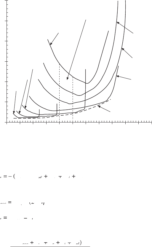
engine ‘braking power or retarding power’ in engine brake operation. Figure
5.1 illustrates the vehicle tractive force characteristics with a seven-speed
transmission.
Denoting t as time, vehicle acceleration a
v
is calculated by:
a
N
t
m
FF
FF
F
v
v
v
ac
FF
ac
FF
ct
FF
ct
FF
rf
FF
rf
FF
ag
FF
ag
FF
F
ag
F
l
=
d
NdN
d
=
(
(
FF +FF
FF
ct
FF +FF
ct
FF
ct
ct
FF
ct
FF FF
ct
FF
+
FF +FF
FF FF
ag
ag
FF
ag
FF FF
ag
FF
+
ag
+
ag
)
1
(
1
(
x
m
x
m
(
x
(
5.8
Vehicle speed is calculated by
NN
at
vt
NN
vt
NN
vt
v
at
v
at
t
t
,,
vt,,vt
21
NN
21
NN
vt
21
vt
,,
21
,,
vt,,vt
21
vt,,vt
1
2
NN =NN
NN
21
NN =NN
21
NN
21
21
NN
21
NN NN
21
NN
vt
21
vt
vt
21
vt
+
d
atdat
Ú
t
Ú
t
5.9
Vehicle travel distance is given by
ll
Nt
vt
ll
vt
ll
vt
v
Nt
v
Nt
t
t
,,
vt,,vt
21
ll
21
ll
vt
21
vt
,,
21
,,
vt,,vt
21
vt,,vt
1
2
ll =ll
ll
21
ll =ll
21
ll
21
21
ll
21
ll ll
21
ll
vt
21
vt
vt
21
vt
+
d
NtdNt
Ú
t
Ú
t
5.10
Vehicle acceleration time is calculated by
D
Ê
Ë
Ê
Á
Ê
Ë
Á
Ë
ˆ
¯
ˆ
˜
ˆ
¯
˜
¯
◊
ÚÚ
tt
ÚÚ
tt
ÚÚ
a
N
m
F
ac
tt
ac
tt
t
ÚÚ
t
ÚÚ
t
ÚÚ
t
ÚÚ
v
N
ÚÚ
N
ÚÚ
N
v
v
ac
F
ac
F
c
v
v
tt =tt
d
ÚÚ
d
ÚÚ
tt dtt
ÚÚ
tt
ÚÚ
d
ÚÚ
tt
ÚÚ
ÚÚ
=
ÚÚ
d
d
Ê
d
Ê
Ë
d
Ë
Ê
Ë
Ê
d
Ê
Ë
Ê
Ê
Á
Ê
d
Ê
Á
Ê
Ë
Á
Ë
d
Ë
Á
Ë
Ê
Ë
Ê
Á
Ê
Ë
Ê
d
Ê
Ë
Ê
Á
Ê
Ë
Ê
ˆ
d
ˆ
¯
d
¯
ˆ
¯
ˆ
d
ˆ
¯
ˆ
ˆ
˜
ˆ
d
ˆ
˜
ˆ
¯
˜
¯
d
¯
˜
¯
ˆ
¯
ˆ
˜
ˆ
¯
ˆ
d
ˆ
¯
ˆ
˜
ˆ
¯
ˆ
ÚÚ
d
ÚÚ
N dN
=
1
ÚÚ
1
ÚÚ
ÚÚ
2
ÚÚ
1
2
1
d
1
d
x
+
++ +
+
d
FF
+FF +
FF
+FF +
N
dNd
tr
tr
FF
tr
FF
+FF +
tr
+FF +
fa
fa
+
fa
+
FF
fa
FF
trfatr
tr
fa
tr
gl
FF
gl
FF
N
N
v
v
v
Ê
Ë
Á
Ê
Á
Ê
Ë
Á
Ë
ˆ
¯
˜
ˆ
˜
ˆ
¯
˜
¯
Ú
N
Ú
N
1
2
5.11
where F
t
is the transient vehicle tractive force resulting from the available
engine transient torque during acceleration in each gear. It should be noted
that under the same fueling rate the transient engine torque is usually lower
than the steady-state engine torque due to losses in combustion, pumping loss,
turbocharger lag, and thermal inertia. In some cases the transient power can
be 5–8% lower than the steady-state power. It is observed that the vehicle
acceleration time from the speed N
v1
to N
v2
is the area under the curve of
‘the reciprocal of acceleration vs. vehicle speed’, plus the gear-shifting
time (typically 0.2–0.6 s for each gear change). The area under the curve
depends on where the transmission gear is shifted. Figure 5.2 shows the
vehicle acceleration characteristics with the full load engine torque curve
for a seven-speed transmission calculated using equation 5.8.
Vehicle dynamics can also be expressed by a power balance as
follows:
Diesel-Xin-05.indd 352 5/5/11 11:49:16 AM
© Woodhead Publishing Limited, 2011
Adhesion limit of dry
concrete road
Adhesion limit
of icy road
Road grade,
aerodynamic and
rolling friction
resistance forces
Vehicle tractive force
Uphill
Level
Downhill
Piston engines cannot produce very high power at low engine speed because its
peak torque is limited. A transmission is needed in order to increase tractive force
Vehicle speed
Over-design
Force reserved for uphill
climbing or acceleration
Design control point at maximum
vehicle speed (near rated power)
This is the constant power curve.
Vehicle power = tractive force times vehicle speed
This is the direction of good drivability. A
smooth constant power curve is ideal for
drivetrain matching. The gaps underneath
power curve are due to discrete gear
numbers and the gaps impede drivability
If the lug curve is shifted up to the dotted
curve, it is an over-design because the vehicle
power at maximum vehicle speed should not
include hill climbing and acceleration
Engine lug curve
at first gear and
second gear
Design control
point at maximum
torque
5.1 Vehicle tractive force characteristics.
Diesel-Xin-05.indd 353 5/5/11 11:49:16 AM
354 Diesel engine system design
© Woodhead Publishing Limited, 2011
WW
WW
WW
ta
WW
ta
WW
cc
WW
rf
WW
rf
WW
rf
WW
ai
WW
ai
WW
WW
ai
WW
g
WW
g
WW
= – (
WW = – (WW
ta
= – (
ta
WW
ta
WW = – (WW
ta
WW
+
WW WW
WW WW
WW
rf
WW WW
rf
WW
WW+ WW
+
ai
+
ai
WW WW
ai
ai
WW
ai
WW WW
ai
WW
WW+ WW
)
5.12
where
WW
ac
WW
ac
WW
cE
WW
cE
WW
ac
ct
WW =WW
WW
cE
WW =WW
cE
WW
(
WW (WW
cE
(
cE
WW
cE
WW (WW
cE
WW
ac
(
ac
ct
(
ct
–
ct
–
ct
)
,
(
,
(
2
ct
2
ct
h
ct
h
ct
5.13
WW
FN
tE
WW
tE
WW
tt
FN
tt
FN
v
WW =WW
WW
tE
WW =WW
tE
WW
tt
tt
tE
tE
WW
tE
WW WW
tE
WW
=
tt
=
tt
h
tE
h
tE
h
5.14
The engine brake power can be calculated by
W
FF
FF
FN
E
W
E
W
ac
FF
ac
FF
cr
FF
cr
FF
fa
FF
fa
FF
crfacr
ig
FF
ig
FF
FN
ig
FN
lv
FN
lv
FN
t
=
– (
FF +FF
FF
cr
FF +FF
cr
FF
cr
cr
FF
cr
FF FF
cr
FF
fa
fa
crfacr
crfacr
+
fa
+
fa
FF +FF
FF FF
ig
ig
FF
ig
FF FF
ig
FF
+
ig
+
ig
)
FN)FN
lv
)
lv
FN
lv
FN)FN
lv
FN
h
5.15
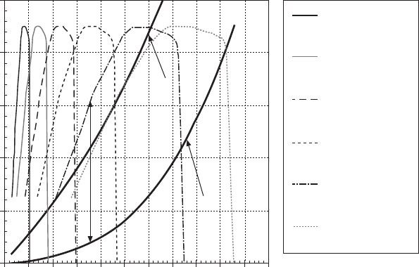
Figure 5.3 illustrates the vehicle tractive power characteristics with a
six-speed transmission. Unlike the torque calculation, the calculation of
the required engine power in equation 5.15 does not relate to the drivetrain
transmission ratio. The difference between the engine brake power and the
vehicle accessory power is the net available power at the inlet of the clutch
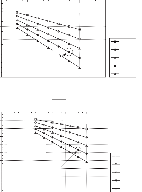
or the torque converter to drive the vehicle. Figure 5.4 shows the calculated
vehicle power requirements under different running conditions.
0 10 20 30 40 50 60 70 80 90 100 110
1 mph = 1.609 km/hr
Vehicle speed (mph)
Reciprocal of vehicle acceleration (1/aV)
6
5
4
3
2
1
0
The area enveloped under gear
7 is the acceleration time from
40 to 50 mph with gear 7
Gear 7
Gear 3
Gear 6
Gear 5
Gear 4
Ideal curve for minimum
acceleration time
Gear 2
Gear 1
5.2 Vehicle acceleration characteristics.
Diesel-Xin-05.indd 354 5/5/11 11:49:17 AM
355Engine–vehicle matching in diesel powertrain system design
© Woodhead Publishing Limited, 2011
5.2 Engine–vehicle steady-state matching in engine
firing operation
5.2.1 Overview of matching criteria
Drivability refers primarily to a wide range of physical experience felt while
driving including acceleration, deceleration, gradeability, transition between
engine operating modes and gear shifts, as well as powertrain NVH during
the events of tip-in, tip-out, takeoff, gearshift, etc. Drivability evaluation is
related to the entire vehicle dynamics engineering and controls, including the
engine, the engine mount stiffness and damping, the powertrain command
and the management of torque-demand coordination, the gearbox stiffness
and inertia, the clutch, the drivetrain, the wheels, the tires, the suspension,
the vehicle body, etc. However, in engine system design, the vehicle driving
performance is usually determined by three aspects: (1) the maximum vehicle
speed on level ground; (2) acceleration time; and (3) the maximum gradeability
under a combined vehicle weight rating at constant speed in rst gear. Overall
vehicle transient acceleration performance is usually characterized by the
time taken to accelerate from 0 to 60 mph, shifting from rst gear to near
the highest gear. Alternatively, it can be characterized by the time spent to
cover a distance of 400 meters. Vehicle launch capability is measured by
the time to accelerate from 5 to 35 mph. Vehicle overtaking capability is
measured by the time to accelerate from 35 to 60 mph or 60 to 80 mph during
Vehicle weight 16 000 lbs, rear axle ratio 3.70
Vehicle power (hp)
250
200
150
100
50
0
0 10 20 30 40 50 60 70 80 90 100 110
Vehicle speed (mph)
The gap here
indicates the
power reserve
for acceleration
or gravity uphill
Total vehicle
resistance
power (rolling
friction plus
aerodynamic)
Total resistance
power (add 6%
uphill gravity)
Engine lug curve
at gear 1
Engine lug curve
at gear 2
Engine lug curve
at gear 3
Engine lug curve
at gear 4
Engine lug curve
at gear 5
Engine lug curve
at gear 6
5.3 Vehicle tractive power characteristics.
Diesel-Xin-05.indd 355 5/5/11 11:49:17 AM
356 Diesel engine system design
© Woodhead Publishing Limited, 2011
acceleration in a high gear. The maximum desirable gradeability is usually
less than 8% uphill grade on highway for heavy-duty commercial vehicles,
and approximately 12–16% in mountains. The maximum gradeability is also
related to the vehicle’s startability.
Vehicle fuel economy is measured by miles per gallon of fuel (mpg) or
liters of fuel per 100 km of travel. Several methods exist to evaluate fuel
economy.
Sensitivity analysis on the effects of vehicle weight and
speed on the power at wheel due to grade gravity resistance
at 7% uphill grade
Vehicle weight (lbs)
5000 10000 15000 20000 25000
Engine brake power required = (wheel
power)/(total drivetrain efficiency)
This condition requires
231 hp engine brake power
with 87% drivetrain efficiency
to only overcome 7% uphill
gravity force resistance, or
requires 402 hp with 50%
drivetrain efficiency
30 mph
40 mph
50 mph
60 mph
70 mph
Power at wheel due to uphill
grade gravity resistance (hp)
0
–50
–100
–150
–200
–250
–300
Sensitivity analysis on the effects of vehicle weight and
acceleration on the power at wheel due to acceleration
resistance on level road at 40 mph
Vehicle weight (lbs)
0 5000 10000 15000 20000 25000
Engine brake power required = (wheel
power)/(total drivetrain efficiency)
This condition requires 268
hp engine brake power with
87% drivetrain efficiency to
overcome acceleration
resistance, or requires 466 hp
with 50% drivetrain efficiency
1.0 mph/s
1.5 mph/s
2.0 mph/s
2.5 mph/s
3.0 mph/s
Power at wheel due to inertia
acceleration resistance (hp)
0
–50
–100
–150
–200
–250
–300
–350
–400
–450
–500
1 mph = 1.609 km/hr
1 hp = 0.7457 kW
1 lbm = 0.4536 kg
5.4 Vehicle power requirements under different operating conditions.
Diesel-Xin-05.indd 356 5/5/11 11:49:18 AM
357Engine–vehicle matching in diesel powertrain system design
© Woodhead Publishing Limited, 2011
1. A curve of the fuel amount consumed in liters per 100 km during cruising
at each constant vehicle speed plotted versus the vehicle speed.
2. The fuel amount consumed in mpg or liters per 100 km for a speci c
driving cycle.
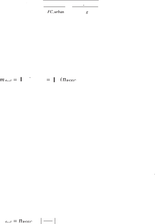
3. The weighted average fuel consumption, for example, the US EPA’s
CAFE composite fuel economy indicator, de ned as
h
hh
FC
composite
hh
FC
hh
hh
ur
hh
hh
ban
hh
FC
hi
,,
composite,,composite
mp
g
,,
hh
,,
hh
hh
ur
hh
,,
hh
ur
hh
hh
ban
hh
,,
hh
ban
hh
FC,,FC
=
1
0.55
+
04
5
.
04.04
ghway
gghwayg
5.16
where h
FC,urban
is the fuel economy of the city (urban) driving cycle
in mpg, and h
FC,highway
is the fuel economy of the highway (suburban)
driving cycle in mpg.
4. Fuel economy during full-pedal acceleration.
The total fuel mass consumed during a driving cycle can be calculated
by
mm
tW
t
fuel
mm
fuel
mm
t
t
BSFC
tW
BSFC
tW
E
tW
E
tW
t
t
mm =mm
d
mm dmm
(
tW (tW
)d
1
1
2
ÚÚ
mm
ÚÚ
mm
tW
ÚÚ
tW
fuel
ÚÚ
fuel
t
ÚÚ
t
t
ÚÚ
t
t
ÚÚ
t
d
ÚÚ
d
mm dmm
ÚÚ
mm dmm
fuel
d
fuel
ÚÚ
fuel
d
fuel
tW =tW
ÚÚ
tW =tW
(
ÚÚ
(
tW (tW
ÚÚ
tW (tW
d
d
ÚÚ
d
d
1
ÚÚ
1
2
ÚÚ
2
h
tW
h
tW
(
h
(
5.17
where
m
fuel
is the fuel ow rate and h
BSFC
is the engine BSFC. If treated
as a quasi steady-state approximation, the BSFC at any non-idle condition
(i.e., engine brake power greater than zero) can be determined at each engine
speed–load point of the driving cycle from the engine BSFC map. The real
transient BSFC must be computed by a high- delity crank-angle-resolution
engine cycle simulation model that re ects the transient combustion ef ciency
and heat losses, as well as the transient pumping loss during turbo lag which
is related to engine controls. A similar approach can be used to compute
the total emissions over the driving cycle if the engine emissions maps
are available. Engine brake power can be computed by vehicle powertrain
transient simulation considering the acceleration inertia effect (equation
5.3). It should be noted that during vehicle deceleration, the fuel rate
m
fuel
is either the idle fueling amount or zero (especially during engine braking),
depending on the vehicle fueling calibration strategy and the use of engine
brake. If the vehicle cruises at a constant speed N
v
to travel a distance L
v
,
the fuel mass consumed can be calculated in simpli ed form as:
mW
l
N
fuel
mW
fuel
mW
BSFC
mW
BSFC
mW
E
mW
E
mW
v
v
mW =mW
h
mW
h
mW
Ê
Ë
Ê
Ë
Ê
Ê
Á
Ê
Ë
Á
Ë
Ê
Ë
Ê
Á
Ê
Ë
Ê
ˆ
¯
ˆ
¯
ˆ
ˆ
˜
ˆ
¯
˜
¯
ˆ
¯
ˆ
˜
ˆ
¯
ˆ
5.18
Engine–vehicle matching analysis was discussed by Chana et al. (1977),
Wong and Clemens (1979), Thring (1981), Phillips et al. (1990), Fluga (1993),
Watson (1995), Jawad et al. (1999), Mikulec and Li (2000), Walker and Ford
Diesel-Xin-05.indd 357 5/5/11 11:49:19 AM