AckermannTh. (ed) Wind Power in Power Systems
Подождите немного. Документ загружается.


//INTEGRAS/KCG/P AGIN ATION/ WILEY /WPS /FINALS_1 4-12- 04/0470855088_ 13_CHA12 .3D – 261 – [257–282/26]
20.12.2004 7:43PM
The IGBT inverters of Type C and D wind turbines are inherently capable of
performing a FACTS function very similar to a stand-alone device, and, as will be
explained in this chapter, have done so with notable success on weak grids. SVC
technology can also be used effectively with Type A and B wind turbines to provide
much the same capability, but with VAR support dropping off with voltage more
rapidly. As SVC devices may be lower in cost it is more feasible to purchase devices
of sufficient size to accommodate voltage drops of as much as 50 %.
Conventional FACTS devices are typically stand-alone products. Most SVCs have
been in the form of large custom facilities requiring substantial field construction, but a
packaged product is emerging. D-VAR
TM
type technology has typically been prepack-
aged and factory built – a product that is delivered, connected and operated but that has
been expensive. The effective integration of this techno logy with wind turbines holds
promise for cost efficiencies while performing to a similar level or adequate level
according to system needs. The distributed mini SVC discussed in Section 12.3.12 and
IGBT Type C or D wind turbine controls allow possible cost efficiencies.
12.2.4 Development of wind energy on the Tehachapi 66 kV grid
The SCE Tehachapi grid of the mid-1980s was designed to serve the Tehachapi–Mojave
area along with the outlyin g High Desert and Mo untain areas. The popula tion of the
area was less than 20 000 people, with the major served load being several large
manufacturing plants, a prison and municipal facilities. The total served load in the
entire area was less than 80 MW, and 60 % of that was two large manufacturing plants.
The area was served from the Antelope substa tion by three 40–70 km 66 kV transmis-
sion lines and 12 kV local distribution lines.
By early 1986, over 300 MW of wind generation was installed, and SCE stopped
further interconnection. The existing grid was more than saturated. Many early wind
turbines were not reliable, and a ‘shake-out’ of good and bad designs quickly elimin-
ated over half the installed capacity. Wind turbine design codes were then generally
nonexistent. The strong winds of Tehachapi soon taught many important lessons to
the infant industry; within months many wind turbines were scrap, and others seldom
ran. Early wind turbines were of small size, and the importance of good siting was not
understood, with many turbines being placed in valleys as well as on good ridge-top
locations. From the combined effect of early wind turbine unreliability, poor siting,
and wind being of different intensity at different locations across the area at any given
time, Tehachapi wind generation delivered from the area peaked near only 125 MW
in 1986.
The combined generation from all wind turbines in an area at any moment in time is
called ‘coincident generation’ and is a key planning and evaluation measure. Wind
blows at different intensities at any instant across a region, and each individual wind
turbine produces more or less energy at any moment depending on the wind at its
location. The peak coincident generation for the region connected to a transmission grid
is the criterium that establishes required facilities since such collected energy is what is
transmitted at any moment and is the actual grid need. Such patterns of generation are
remarkably consistent and repeatable.
Wind Power in Power Systems 261

//INTEGRAS/KCG/P AGIN ATION/ WILEY /WPS /FINALS_1 4-12- 04/0470855088_ 13_CHA12 .3D – 262 – [257–282/26]
20.12.2004 7:43PM
Early grid-related problems were generally associated with unreliability caused by the
extensive web of 66 kV lines spread across the desert and mountains, subject to physical
damage, lightning strikes and increased loading. Protection schemes were simplistic;
control was manual, and operating data were scarce and slowly updated. The skill of a
few experienced SCE grid operators contributed substantially to making the marginal
66 kV grid work.
Computer-based wind turbine controllers were uncommon before 1985, and control
functions were limited in sophisticat ion and flexibility. Controller reliability generally
was low. Utility protection and monitoring schemes were similarly limited in flexibility
and were generally designed for operation with large central generation from synchron-
ous generators capable of providing their own excitation and VAR support for the
grid.
The utilities were generally unfamiliar with distributed generation and particularly
with induction generators. Utility engineers were first mostly concerned about fault
clearing and then about self-excitation and islanding in relation to safety issues on the
grid. A nearby dramatic resonance event, experienced with transmission line series
capacitor VAR support, resulted in major damage to the large Mohave generating
station and created excessive caution about VARs generally. There was little experience
or understanding about the importance of VAR support for inducti on generators and of
the difficulty of transporting VARs over the transmission system. Contractual rules
were thus written severely to restrict wind farms from providing meaningful VAR
support, and the foundation for years of difficulty was laid.
12.2.5 Reliable generation
From 1986 through 1991, the US wind industry went through a period of substantial
technical and economic challenge, including the bankruptcy or collapse of nearly all
wind turbine manufacturers and many wind farms. Warranty obligations were abro-
gated and the responsibility for the resolution of technical problems shifted from the
bankrupt entities to the surviving projects. The local industry worked hard to resolve the
technical and economic problems and to get the early turbines to achieve reliable
production. Those efforts were quite successful, and by 1991 peak coincident generation
from the Tehachapi turbines was well above the then 185 MW grid transfer capability.
It became clear that wind energy could provide reliable generation in productive wind
resource areas. The utility then made hefty curtailment payments rather than build
major transmission, and justified this by the very low cost replacement energy then
available from surplus supplies in the Pacific Northwest. Such short-sighted decisions
resulting from flawed economic reasoning and self-interest are still being corrected.
Repowering of original projects was tested experimentally in 1996 and 1997 with
substantial success. A small number of 500 kW and 600 kW Type A wind turbines
replaced original 25 kW to 65 kW wind turbines. Careful siting of the new turbines gave
far more productive kilowatt-hours per installed kilowatt, and the new turbi nes demon-
strated substantial reliability. The con cept of using tall towers in complex terrain to gain
low turbulence and improved suitability was proven. Then, in 1999, there was a
substantial repowering of nearly 45 % of the installed capacit y on the Tehachapi
262 Wind Power on Weak Grids

//INTEGRAS/KCG/P AGIN ATION/ WILEY /WPS /FINALS_1 4-12- 04/0470855088_ 13_CHA12 .3D – 263 – [257–282/26]
20.12.2004 7:43PM
66 kV grid. Projects with a capacity factor of 12 % to 20 % or less quickly achieved
capacity factors of 35 % to 45 %. Peak coincident generation on the 66 kV grid
increased dramatically to 310 MW while total installed capacity remained at 345 MW.
(Muljadi et al., 2004).
The increased transfer capability was achieved in progressive steps from 1999 to 2002:
although two small transmission upgrades substantially underperformed design expect-
ations, increased windfarm-supplied VARs proved to be extremely effective. In this
process, a VAR rationing programme was instituted. The available utility VARs were
rationed to each windfarm based on its capacity, and each windfarm had to curtail its
output to stay within its VAR allocation. Individual wind-farm transfer capability was
thus within the control of each entity, and the economic incentive correctly caused the
installation of substantial VARs at the most effective location on the system with
dramatically improved transfer capability.
12.2.6 Capacity factor improvement: firming intermittent wind generation
In 2001, an evaluation of the Tehachapi grid showed that while the grid was operating
near 100 % capacity for some periods of time, the annual capacity factor for all wind
generation on the 66 kV grid was only 27 %. It also showed that if 100 MW of energy
storage and wind energy were added, the annual grid capacity factor would be increased
to 41 %, while not increasing maximum generation transfer on the grid. Current plan-
ning rules in California have not allowed this added capacity, which sits idle for much of
the year, to be effectively utilized, this added capacity thus represents a substantial
economic opportunity. For intermittent resources, such firming would reduce the
environmental footprint of transmission through fewer lines, and increasing its value
as a dispatchable, more predictable resource.
In 1992 and 1993 I designed and operated a 2.88 MW 17 280 kWh battery storage
facility in the San Gorgonio area, integral with wind generation. The project was the
second or third largest battery storage project ever built at the time. It operated
successfully for two annual peak seasons for the purpose of meet ing firm capacity
contract obligations prior to the repowering of an early wind farm. The batteries were
surplus submarine batteries, controlled by thyristor inverters, organized in 360 kW
modules with six hours storage.
Evolving energy-storage technology will utilize IGBT converters similar to those
associated with Type D wind turbines to give a substantial opportunity for enhanced
VAR support. When combined with sufficient energy storage capability to create a
higher-quality dispatchable wind energy product, transmission facilities can be more
fully utilized, costs spread across a larger base, and environmental footprint redu ced
with fewer transmis sion lines.
Current grid planning rules provide only firm transmission rights, so that a very
substantial opportunity to utilize grid capacity more efficiently is going to waste.
Substantial new transmission capacity costs in the range of 30 % to 60 % of the cost
of modern efficient wind farms. It is economically efficient to plan to curtail generation
for modest periods annually in order better to balance wind farm cost with trans mission
cost with or without energy storage.
Wind Power in Power Systems 263

//INTEGRAS/KCG/P AGIN ATION/ WILEY /WPS /FINALS_1 4-12- 04/0470855088_ 13_CHA12 .3D – 264 – [257–282/26]
20.12.2004 7:43PM
12.3 Voltage Regulation: VAR Support on a Wind-dominated Grid
The Tehachapi 66 kV grid, as noted above, is dominated by over 300 MW of wind
energy generation with only 80 MW of local load. Type A wind turbines predominate,
with some Type B and a few Type C turbines. In Tehachapi it is necessary to control the
voltage through the use of VAR support, and the lessons learned in Tehachapi are
important. Chapter 19 presents a good overview and background on voltage control
and VAR support generally, whereas the discussion here is focused on specific cases
associated with weak grids and wind generation dominating the energy flows. In such
cases, VAR support and its effective control is critical to voltage support, and its
absence will result in either voltage collapse or grid instability. Tehachapi has experi-
enced both conditions and today is reasonably reliable as a result of the implementation
of effective VAR support and selective grid upgrades.
A weak grid can be defined as one where the connected induction machine kilowatt
rating exceeds 15 % of the gateway short-circuit S
k
. In Tehachapi, wind power in excess
of 40 % S
k
is su ccessfully being operated. With 345 kW of connected Type A and Type B
wind turbines producing 310 MW coincident generation and a gateway short-circuit
duty of 560 MVA at Cal Cement, it is clear that Tehachapi can be considered an
extremely weak grid.
Another major consideration is that weak grids do not transport VARs well. VARs
impact the devices and facilities in their local area to a greater extent. They are partially
consumed as they are transported along transmission and distribution lines and as they
pass through transformers.
Transmission and distribution lines exhibit a generally capacitive characteris tic when
lightly loaded and become increasingly inductive as load increases. Some long heavily-
loaded lines can be remar kably inductive when heavily loaded. Such characteristic
behaviour has a major impact on weak grids and will cause instability or voltage
collapse if not effectively dealt with. Tehachapi has experienced both.
12.3.1 Voltage control of a self-excited induction machine
An often talked about but little-used generating machine is the self-excited induction
generator. The most common use of this technology has been with small stand-alone
generators and a captive fixed load. Capacitors are connected to the induction machine
to provide the self-excitation, and the amount of capacitance connected determines the
voltage level based on the operating point on the induction machine’s saturation curve.
The greater the capacitance, the farther up the saturation curve the induction machine
operates and the higher the voltage. Increasing load consumes increasing VARs within
the induction machine, and stable operation with acceptable regulation can be achieved
for applications where the load is reasonably steady and well-defined.
12.3.2 Voltage regulated VAR control
This same technique can be applied to wind energy induction generators associated with
Type A and Type B wind turbines. Here, however, the load is not steady, generation is
264 Wind Power on Weak Grids
//INTEGRAS/KCG/P AGIN ATION/ WILEY /WPS /FINALS_1 4-12- 04/0470855088_ 13_CHA12 .3D – 265 – [257–282/26]
20.12.2004 7:43PM
widely variable with wind speed and effective control is much more difficult. In the
normal situation of marginal VAR support, grid voltage drops with increasing wind
generation. It is possible and practical to use transient-free, fast thyristor control of
capacitors to achieve good flat voltage regulation of an induction machine in a wind
farm environment and voltage control to dampen out grid oscillations, to the extent that
those are desired objectives. This result can also be achieved from the inherent wave-
shaping capability of an IGBT inverter as associated with Type C and D wind turbines. In
either case, the induction machine can be made to behave very similarly to a synchronous
generator, with VAR support for the external grid, and voltage control, and thus be very
‘friendly’ to the grid.
12.3.3 Typical wind farm PQ operating characteristics
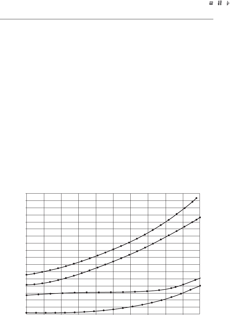
Typical curves of operating induction generators on the Tehachapi grid are shown in
Figure 12.2. All four curves are for Type A wind turbines, with VAR support and
controls having different VAR support capabilities. One of them shows the effects of
less-than-good maintenance. In each case, the data are for an array of wind turbines at
the point of interconnection, with no substation transformer included, but with the wind
turbine transformers and internal wind farm collection grid included. Voltage regulation
causes an approximately 6 % drop from light generation to heavy generation. Reduced
grid voltage reduces VAR consumption at heavy generation and increased VARs are
(
1
)
O
r
i
g
i
n
a
l
1
9
8
0
s
v
i
n
t
a
g
e
T
y
p
e
A
W
T
s
–
c
a
p
s
n
e
e
d
m
a
i
n
t
e
n
a
n
c
e
(
2
)
O
r
i
g
i
n
a
l
1
9
8
0
s
v
i
n
t
a
g
e
T
y
p
e
A
W
T
s
–
p
r
o
p
e
r
l
y
m
a
i
n
t
a
i
n
e
d
(
3
)
S
i
m
i
l
a
r
1
9
8
0
s
v
i
n
t
a
g
e
T
y
p
e
A
W
T
s
w
i
t
h
i
m
p
r
o
v
e
d
V
A
R
c
o
n
t
r
o
l
(
4
)
R
e
p
o
w
e
r
e
d
T
y
p
e
A
W
T
s
w
i
t
h
i
n
t
e
r
n
a
l
V
A
R
s
u
p
p
o
r
t
0.850
0.800
0.750
0.700
0.650
0.600
0.550
0.500
0.450
0.400
0.350
0.300
0.250
0.200
0.150
0.100
0.050
0.000
0.800 0.900 1.0000.7000.6000.5000.4000.3000.2000.1000.000
p.u. kW
p.u. kVAR
Figure 12.2 PQ characteristics of Tehachapi area Type A wind turbine (WT) arrays. Note: curve
(4) is identical to Curve (4) in Figure 12.3, but note the scale change
Wind Power in Power Systems 265
//INTEGRAS/KCG/P AGIN ATION/ WILEY /WPS /FINALS_1 4-12- 04/0470855088_ 13_CHA12 .3D – 266 – [257–282/26]
20.12.2004 7:43PM
required to maintain a flat grid voltage. These curves, as normalized, are quite repre-
sentative of weak grid conditions experienced and are directly comparable.
Curve (1) of Figure 12.2 is of a wind farm of original 1980s vintage Type A wind
turbines with the conventional no-load VAR control of that era but with the VAR
control not effectively maintained, a common occurrence with that type of early control
system. Curve (2) is of the same wind farm, but with the controls properly maintained in
good and fully functional condition. For a 10 MW project, the difference represents a
loss of 1.5 MVAR of critical VAR support at the most valuable location for those
VARs.
Curve (3) of Figure 12.2 is of a different wind farm with similar 1980s vintage Type A
wind turbines, but with improved VAR control. The conventional no-load capacitors
have been increased to above-no-load VARs, the wind turbine transformers and wind
farm collection grid have been compensated with fixed capacitors and a capacitor bank
is switched with generation-level, materially increasing, local VAR suppo rt. This level of
VAR support at the most valuable location for those VARs for a 10 MW project
represents about 6 MVAR of added VARs. This is a substantial and significant
increased benefit for improved grid performance and is one of the improvements that
have materially raised the transfer capability of Tehachapi.
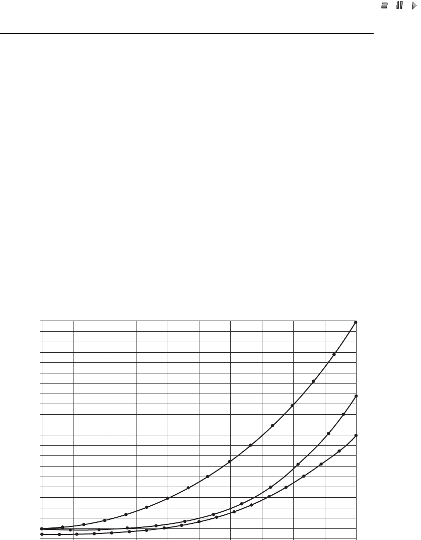
Curve (4) of Figures 12.2 and 12.3 is of a different wind farm with repowered Type A
wind turbines. These turbines have impr oved VAR support as a part of the turbine
0.380
0.400
0.420
0.360
0.340
0.320
0.300
0.280
0.260
0.240
0.200
0.220
0.180
0.160
0.140
0.120
0.100
0.060
0.080
0.040
0.020
0.000
0.800 0.900 1.0000.7000.6000.5000.4000.3000.2000.1000.000
p.u. kW
p.u. kVAR
(
6
)
R
e
p
o
w
e
r
–
c
a
s
e
o
f
c
u
r
v
e
s
(
4
)
a
n
d
(
5
)
w
i
t
h
1
.
1
p
.
u
.
s
u
b
s
t
a
t
i
o
n
(
5
)
S
i
m
i
l
a
r
r
e
p
o
w
e
r
T
y
p
e
A
W
T
s
a
n
d
0
.
7
5
p
.
u
.
s
u
b
s
t
a
t
i
o
n
(
4
)
R
e
p
o
w
e
r
e
d
T
y
p
e
A
W
T
s
w
i
t
h
i
n
t
e
r
n
a
l
V
A
R
s
u
p
p
o
r
t
Figure 12.3 PQ characteristics of Tehachapi area Type A wind turbines (WTs) and substation;
Curve (4) corresponds to the case where there is no substation and, is identical to Curve (4) in
Figure 12.2 (note the scale change)
266 Wind Power on Weak Grids

//INTEGRAS/KCG/P AGIN ATION/ WILEY /WPS /FINALS_1 4-12- 04/0470855088_ 13_CHA12 .3D – 267 – [257–282/26]
20.12.2004 7:43PM
design with five steps of capacitors switched in and out to maintain approximately zero
VARs at the wind turbine main breaker until 75 % of the VAR demand of the turbine is
reached. This level of internal VAR support represents about 6.5 MVAR of added
VARs at the most valuable location.
With Type A and B win d turbines it is quite feasible to add yet further effective VAR
support using the same scheme as in Curve (4) but with further added VARs at the wind
turbines, increasing VAR support to provide essentially all of the VARs that the
turbines are consuming. Such an arrangement would provide approximately 8.5 MVAR
at the most critical location for a 10 MW project. As added VAR support increases, it is
important that the control scheme be configured to discon nect the capacitors very
rapidly above no-load VARs to avoid driving the induction machine into saturation
when an islanding event occurs. The typical speed of response appropriate for such an
event is a few tenths of a second (see Section 12.3.9).
Figure 12.3 shows data for two comparable repowered Type A wind turbine projects,
but including a project substation, it also shows Curve (4) from Figure 12.2 for
comparison. Note that the p.u. kVAR scale is different from that in Figure 12.2. Heavily
loaded substation transformers and long internal collection lines require substantial
added VARs.
Curve (5) of Figure 12.3 is of a project with Type A wind turbines and is very similar
to the situation represented by Curve (4), but with a modestly loaded substation
(0.75 p.u.) and some internal supplemental VAR support of the type associated with
the Curve (3) project of Figure 12.2, but of lesser relative magnitude.
Curve (6) of Figure 12.3 is of the two projects combined, of both Curve (4) and Curve
(5) with different collection, and both fed into the substation associated with Curve (5).
The resulting substation loading is at 1.1 p.u. in this case, and that increased loading
materially increases VAR consumption. The added VAR support demands created by
the heavily loaded substation are material and must be accommodated.
12.3.4 Local voltage change from VAR support
Local voltage changes associated with changes in VAR support can be reasonably pre-
dicted. As pointed out in Chapter 19, the impact of VAR support is greater on higher-
impedance grids and lesser on low-impedance grids. On weak grids, the relative impedance
is usually quite high and the impact of VAR support is usually significant. It is useful to be
able to predict the general voltage impact that changes in VAR support will provide. The
relationship described by the following formula is useful in making such predictions:
percentage voltage change ¼
MVAR change 100
three-phase short-circuit duty, in MVA
ð12:1Þ
From this relationship one can see that VAR changes on a stiff grid have relatively small
impact, but on weak grids the impact can be relatively large. The difference between the
VAR support of Curves (5) and (6) in Figure 12.3 will cause about 1.2 % voltage change on
a normal fully loaded substation transformer, and the impact of Curve (1) of Figure 12.2 will
cause about a 6 % voltage change. On a stiff grid, where the wind turbines are a small part of
the total connected load, these same VAR impacts will have negligible voltage impact.
Wind Power in Power Systems 267

//INTEGRAS/KCG/P AGIN ATION/ WILEY /WPS /FINALS_1 4-12- 04/0470855088_ 13_CHA12 .3D – 268 – [257–282/26]
20.12.2004 7:43PM
12.3.5 Location of supplying VARs within a wind farm
There is a strong advantage in supplying VAR support for induction machines at or
near the induction machine, particularly considering the system topology of typical
wind farms. By providing it at the wind turbine the increased risk of ferro-resonance is
diminished, and harmonic problems and risks are less likely to arise. Also, effective use
can be made of wind turbine power system components, resulting in a lower-cost and
more easily maintained system.
In standard project design, each wind turbine sits behind its own transformer,
having significant impedance, typically 5 % to 6 %, and also behind the wind farm
substation transformer and collection system. Substation transformers typically
have 7 % to 8 % impedance, but since these have a far larger rating than any wind
turbine and may serve many wind turbines their impedance impact at the individual
turbine is relatively small. Some applications of VAR capacitors use dampening
inductance inserted with each bank of capacitors. These typically are in the order of
6 % to 7 % impedance. The available transformer impedance, coupled with careful
system design, can achieve low harmonic currents without the added cost and
complexity of the dampening inductors. Dampening inductors have generally not
been used on most wind farm capacitor installations in the USA and, where they
have been used, they have not dramatically diminished harmonic issues but do
reduce harmonic currents.
In Figure 12.4, the voltage impact of VAR support capacitors is shown for a variety
of locations for the VARs – at the wind turbine, on the wind farm collection system and
externally, on the high voltage (HV) grid, usually supplied by the utility.
Wind turbine case (a) in Figure 12.4 is of a typical Type A or B wind turbine with no-
load VAR support, what has typically been the standard product offering of most
manufacturers. In this configuration, and wi th a good, low VAR demand generator,
there will be about 1.8 % voltage drop at the wind turbine. This is solely attributable to
inadequate VARs causing a drop in generator voltage with increasing generation.
Wind turbine case (b) in Figure 12.4 has sufficient supplemental VARs at the wind
turbine to carry its share of the VARs need ed to provide a 0.95 power factor at the point
of interconnection. This causes a 3.7 % increase in generator voltage at the turbine. One
or two tap adjustments on the wind turbine transformer can accommodate that voltage
rise, and this will also cause the transformer to be less saturated – a desirable situation.
Lower saturation is also helpful with harmonics.
There are other significant issues that must also be addressed with respect to island-
ing, and one of the consequences of detail oversight is shown later, in Figure 12.7. In the
case illustrated, slow-acting medium-voltage vacuum breakers acted slowly and left
VAR support on an island for far too long. When the energy transfer stopped, this
resulted in a substantial overvoltage condition for a short period (see Section 12.3.9).
Interestingly, Figure 12.9 is of the same event, and at that facility the event was handled
without significant consequence (see Section 12.3.11). On the island, the excess VARs
caused the Type A or B induction machines to overexcite and climb to the maximum of
their saturation curve until the condition cleared.
Good protection and a reasonably rapid speed of response to such conditions is
important. Generally, 0.2 to 0.3 seconds is an adequate and effective time to clear
268 Wind Power on Weak Grids
//INTEGRAS/KCG/P AGIN ATION/ WILEY /WPS /FINALS_1 4-12- 04/0470855088_ 13_CHA12 .3D – 269 – [257–282/26]
20.12.2004 7:43PM
VAR support in the event of an island and, in the event illustrated in Figure 12.7 would
have prevented such an overvoltage condition.
12.3.6 Self-correcting fault condition: VAR starvation
Similar VARs applied solo to the low voltage side of a transformer bank as shown in
Case (b) of Figure 12.4 causes double the voltage rise on the low voltage side of the
transformer, and must be considered in the design, but can be beneficial.
Capacitors applied on the medium-voltage wind farm collection system, as shown in
Figure 12.4, will have a reduced voltage impact because of the lower impedance and
higher S
k
duty. At this location, the VARs must pass through the wind turbine
transformer, and its inductance, before reaching the generator, a critical need location.
This location has commonly been used for placing VAR support capacitors since larger
increments of VARs can be supplied in small packages, and the convenience is high.
However, this location is at higher risk of damaging impacts from harmonic conditions,
and these capacitor designs normally do not have dampening inductors feasibly avail-
able. Further, some vacuum breakers commonly used for such installations are slow
acting and can lead to quite undesirable overvoltage conditions in an islanding event
(Section 12.3.9, Figure 12.7).
Utilities commonly supply the VAR support that they provide from the high-voltage
grid, usually from capacitors located at utility substations. Such a location is conveni-
ent, but is far from the consuming generators and has significant limitations.
Individual wind turbineWind farm collectionGrid
High voltage Medium voltage Low voltage
Voltage control
Best practice
Wind turbine case (b): weak grid
Wind turbine
case (b)
Wind turbine
case (a)
Strong grid
1 WT 0.1 % dU (20 % S
K
)
1 WF 2.2 % dU (20 % S
K
)
All WF 10.5 % dU (20 % S
K
)
All WF 21.0 % dU (40 % S
K
)
All WF 2.6 % dU (5 % S
K
)
Wind turbine case (b):
1 WT 0.4 % dU
All WTs 7.0 % dU
+7.4 % dU
+3.7 % dU
–1.8 % dU
1.2 Q
/P
0.9 Q /P
0.3 Q /P
0.3 Q/P
Figure 12.4 Voltage impact of VAR support at alternate locations in the system; the figure shows
the voltage impact of VARs on weak and strong grids. Note the potential for small increment control
from block switching individual wind turbine VARs. Note:WF¼ wind farm; WT ¼ wind turbine;
U ¼ voltage; Q ¼ reactive power; P ¼ active power; S
k
¼ short-circuit power
Wind Power in Power Systems 269
//INTEGRAS/KCG/P AGIN ATION/ WILEY /WPS /FINALS_1 4-12- 04/0470855088_ 13_CHA12 .3D – 270 – [257–282/26]
20.12.2004 7:43PM
In Tehachapi, just over 100 MVAR is supplied from within substations, and another
50 MVAR from the distant Antelope Substation is ineff ective. SCE was unable to locate
adequate VARs at its facilities, and it was necessary to locate the great majority of the
VARs needed by the wind farm within the wind farm.
Block control of supplemental capacitors at a wind turbine can be used as an efficient
technique to manage harmoni cs effectively and to provide a simple and low-cost
distributed virtual control scheme. One can achieve effective and fine control of collec-
tion voltage and grid voltage by selectively switching one block at a time. A single Case
(b) wind turbine will change system voltage at the collection level by only 0.4 %, or at
the grid level by only 0.1 %.
12.3.7 Efficient-to-use idle wind turbine component capacity for
low-voltage VARs
The effective loading of a wind turbine transformer is not generally impacted significantly
by the addition of supplementary VAR capacitors in addition to those supplied with the
turbine controller on a Type A or B wind turbine. This is particularly true starting from
standard no-load VARs that are about 50 % of the compensation required for a wind farm.
Power system components are generally sized to carry the full load generator current
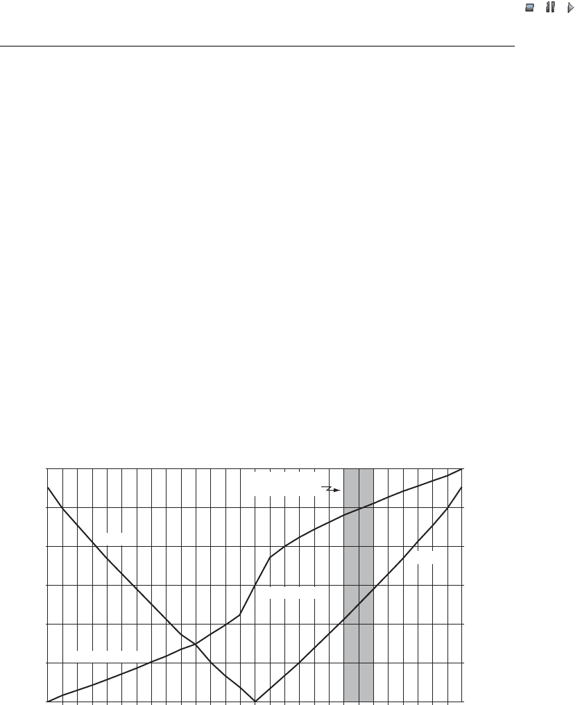
without considering the reduced current with any level of VAR support. In Figure 12.5,
this is about 1.16 p.u. current, based on a unity power factor. As can be seen, one could
VAR support
Q
S/P
S/P (kVA/kW)
1.2 1.18
1.15
1.12
1.09
1.06
1.03
1.00
1.0
0.8
0.6
0.4
0.2
0.0
p.u.Q (p.u. kVAR)
–0.86
–0.88
0.86
–0.90
0.90
0.88
–0.92
0.92
–0.94
0.94
–0.96
0.96
–0.98
0.98
1.00
Producing VARs
Power factor
Consuming VARs
S/P
VAR support Q
VARs for 0.95
at interconnect
Figure 12.5 VAR impact at wind turbine does not increase major system component size. All of the
VARs needed in a wind farm can be supplied efficiently at low voltage. Note: Q ¼ reactive power;
P ¼ active power; S ¼ apparent power; p:u: ¼ per unit
270 Wind Power on Weak Grids