AckermannTh. (ed) Wind Power in Power Systems
Подождите немного. Документ загружается.


//INTEGRAS/KCG/P AGIN ATION/ WILEY /WPS /FINALS_1 4-12- 04/0470855088_ 13_CHA12 .3D – 271 – [257–282/26]
20.12.2004 7:43PM
go to 0.86 power factor producing VARs and still remain within the normal design
margin. VARs producing a full generat ion power factor of about 0.92 or 0.93 will
usually give the VARs necessary to achieve a 0.95 power factor at the point of inter-
connection, the level now required of new installations. In the case illustrated in Figure
12.5, 0.95 can be achieved well within code required design margin, certainly with the
extra capacity provided by wind cooling of pad mount transform ers.
12.3.8 Harmonics and harmonic resonance: location on grid
When one uses capacitors for VAR supply, it is crit ical to consider harmonics and
harmonic resonance and to design carefully to avoid negative impacts from the intro-
duction of capacitive VARs onto a system. Resonance is the point where the inductive
impedance of the connected facilities equals the capacitive impedance of the capacitors,
at a given frequency. Thus, at that point, the two impedances cancel each other out, and
only the usually small resistance of the network limits current flow. The typical scenario
is that resonance is most significant at the third, fifth, or seventh harmonic of system
frequency. Although the voltages are low at these harmonics, the very small resistance
can produce destructive currents and other undesirable effects.
Ferro-resonance is common with electromagnetic machines, and harmonics exist in
all electric systems to a greater or lesser degree. Transformers tend to operate at
sufficiently high saturation levels as to generate sufficient harmonics, particularly of
the seventh order and below, to create the need for careful attention in the best of
systems. Phase-controlled thyristor power controllers, if they exist on a network, often
create rich harmonics, and create a need for greater attention. It is good practice to pay
substantial attention to harmonics when applying VAR support capacitors to any
specific grid, and actual measurement across a full set of conditions is essential. Con-
tinuous monitoring is a good idea, as installations and operating conditions change, and
the cost of effective monitoring is not great if the monitoring is well organized. Failure
to accommodate harmonic issues can lead to premature capacitor failures and, in the
worst cases, to other significant consequences.
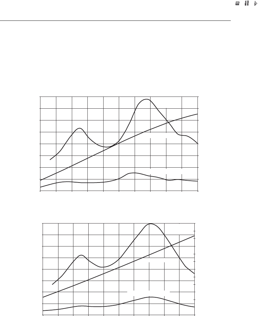
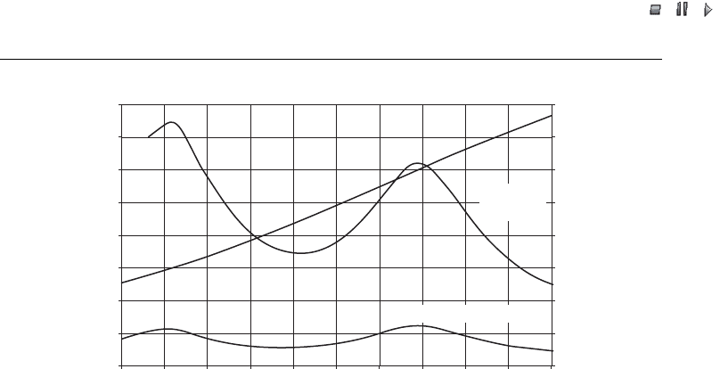
Figures 12.6(a)–12.6(c) (note the THD scale changes) give a view of the range of
harmonic conditions at the wind turbine main terminals, as operating conditions
change. Depending on operating point, resonance can be problematic over a fairly
broad range. The impedance of an induction machine changes with generation level,
along with its VAR requir ement. Harmonic resonance does not become significant in
most clean syst ems where VAR support is less than unity. Supplying large blocks of
positive VARs from behind the impedance of a transformer and/or dampening induc-
tors is also outside the range of usual clean system resonance and produces low levels of
harmonics, particularly at medium and high generation, when VARs are most needed.
The location of the capacitors in the network makes a significant difference. VARs
supplied by the utility from capacitors, generators or other sources are generally not as
effective nor as efficient in terms of VARs needed to be installed compared with VARs
needed at the induction machines. The local collection grid, distribution grid and
transmission grid all also consume VARs, particularly at higher energy flows, and this
must be accommodated. Needs local to the wind farm can usually be effectively supplied
Wind Power in Power Systems 271
//INTEGRAS/KCG/P AGIN ATION/ WILEY /WPS /FINALS_1 4-12- 04/0470855088_ 13_CHA12 .3D – 272 – [257–282/26]
20.12.2004 7:43PM
from the wind farm , quite like what is done from a conventional generator, provided the
VARs are available. Although this discussion is of the historical opposite condition, it is
likely that VAR supply from each wind farm will be required for new interconnection
and will improve the system particularly where the control strategy is effective, such as
with fast-responding voltage control.
The location of the capacitors and method of control also have a significant impact
on harmoni c resonance and the range of exposure to resonance. The wind turbine
THD (%)
Supplemental VARs (p.u.)
Voltage (p.u.)
1.03
1.02
1.01
1.00
0.99
0.98
0.97
0.96
0.95
0.0 0.1 0.2 0.3 0.4 0.5 0.6 0.7 0.8 0.9 1.0
0
1
2
3
4
5
6
7
8
(a) WT near full generation
Percentage U THD
U VOLTS
Percentage
I
z
THD
U VOLTS
Percentage U THD
THD (%)
Supplemental VARs (p.u.)
Voltage (p.u.)
1.03
1.02
1.01
1.00
0.99
0.98
0.97
0.96
0.95
0.0 0.1 0.2 0.3 0.4 0.5 0.6 0.7 0.8 0.9 1.0
0
1
2
3
4
5
6
7
8
9
10
11
12
Percentage
I
z
THD
(b) WT at half generation
Figure 12.6 Total harmonic distortion (THD) and voltage, U, as a function of per unit (p.u.)
supplemental VARs (note the THD scale): VAR capacitors at secondary of wind turbine (WT)
transformer and (a) WT near full generation; (b) WT at half generation and (c) WT at 10 %
generation. Note: I
z
– capacitor current
272 Wind Power on Weak Grids
//INTEGRAS/KCG/P AGIN ATION/ WILEY /WPS /FINALS_1 4-12- 04/0470855088_ 13_CHA12 .3D – 273 – [257–282/26]
20.12.2004 7:43PM
transformer introduces typically 5 % to 6 % impedance and is sized close to the rating of
the turbine. A substation transformer typically ha s 7 % to 8 % impedance, but serves a
large number of turbines. It therefore generally has a small impact on the characteristic
impedance when seen at any individual wind turbine. Thus, by locating VAR capacitors
on the wind turbine side of its transformer, one finds a location less exposed to wide
variations in impedance. Also, by using a Delta–Wye or Wye–Delta transformer con-
figuration, one eliminates the third harmonic. These factors combined can materially
reduce the risk of harmonic resonance in many installations. Effective transformer
impedance is substantially increased when the transformer is applied near its maximum
capability such as with forced cooled designs.
Lightly loaded transmission lines exhibit a capacitive characteristic. Heavily loaded lines
exhibit a substantial inductive characteristic. As line loading passes the point of surge
impedance loading (SIL) VAR consumption can increase materially. Similarly, trans-
formers when lightly loaded require modest VARs for excitation but when heavily loaded
consume substantial VARs. These factors are generally not well evaluated and considered
in project design and often lead to unpleasant surprises and impacts on weak grid systems.
Conventional transmission network analytical tools have not accurately modelled and
predicted grid behaviour associated with substantial installation of induction machines.
Only now are improved models beginning to predict grid performance at a reasonable level.
Tehachapi has clearly seen such consequences of inadequate models and poor understand-
ing of the issues, as have West Texas and Minnesota. As a result, improved models have
been developed and reasonably validated, with more to follow, and the result is that others
will soon have reasonable tools that can provide good results. However, care is needed, and
attention to critical details is quite important to avoid unexpected and unpleasant results.
The medium-voltage collection grid is another common location for VAR support
capacitors. That location can provide a low-cost installation for a large block of
U
THD (%)
Supplemental VARs (p.u.)
Voltage (p.u.)
1.03
1.02
1.01
1.00
0.99
0.98
0.97
0.96
0.95
0.0 0.1 0.2 0.3 0.4 0.5 0.6 0.7 0.8 0.9 1.0
0
5
10
15
20
25
30
35
40
(c) WT at 10%
g
eneration
Percentage
I
z
THD
Percentage U THD
Figure 12.6 (continued)
Wind Power in Power Systems 273

//INTEGRAS/KCG/P AGIN ATION/ WILEY /WPS /FINALS_1 4-12- 04/0470855088_ 13_CHA12 .3D – 274 – [257–282/26]
20.12.2004 7:43PM
such capacitors and controls, but caution is indica ted, as the range of harmoni c
exposure is materially increased, and some medium-voltage control devices are
slow to operate and thus introduce added exposures that must be accommodated
(see Section 12.3.9).
The early design FACTS device applied in Tehach api is a 14.4 MVAR 12-step capacitor-
only system using transient free, fast thyristor switching. This unit is located at the most
critical VAR support node and has achieved excellent results, but there are notable
issues; 14.4 MVAR is too small for the system needs, and, although it gives excellent
performance at light and medium generation, it saturates before high generation when it
is needed most. An attempt to add fixed 5 MVAR steps was not successful because of
unresolved resonance problems. During light generation, resonance problems when in
automatic control have resulted in excessive maintenance and out-of-service events,
despite being behind the substantial impedance of dampening inductors and two steps
of transformers. It is likely these problems could be readily managed and more
effectively operated by using harmonic feedback information and smarter control.
VAR capacitors are designed to work satisfactorily when exposed to relatively high
harmonics, with various codes commonly requiring a design margin of 1.3 or 1.35 above
nominal current to accommodate unanticipated harmonic currents. The full circuit
design must be sized accordingly, including capacitor contactor, breaker, fuses and
wiring. Although capacitors can survive in relatively high harmonics, it is good practice
to employ control strategies that cause operation away from harmonic resonance and
increase reliability and longevity. It is also important to derate capacitors by applying
them at below their rated voltage to achieve an appropriately long life with low main-
tenance costs. Keeping capacitors cool is also important to their long life.
12.3.9 Islanding, self-correcting conditions and speed of response for VAR
controls
Islanding is a condition where a wind turbine, a wind farm or a group of wind farms and
their associated grid becomes separated from the full grid and may perform as an
independent island, if conditions are right to support continued operation without
tripping equipment or facilities. There are many risks associ ated with islanding, and
great efforts are taken to prevent this from occu rring. Among the greatest risks may be
major damage to equipment if an island is reclosed onto the main grid when out of
synchronisation, and the safety of repair crews expecting a de-energized grid and
shockingly discovering otherwise.
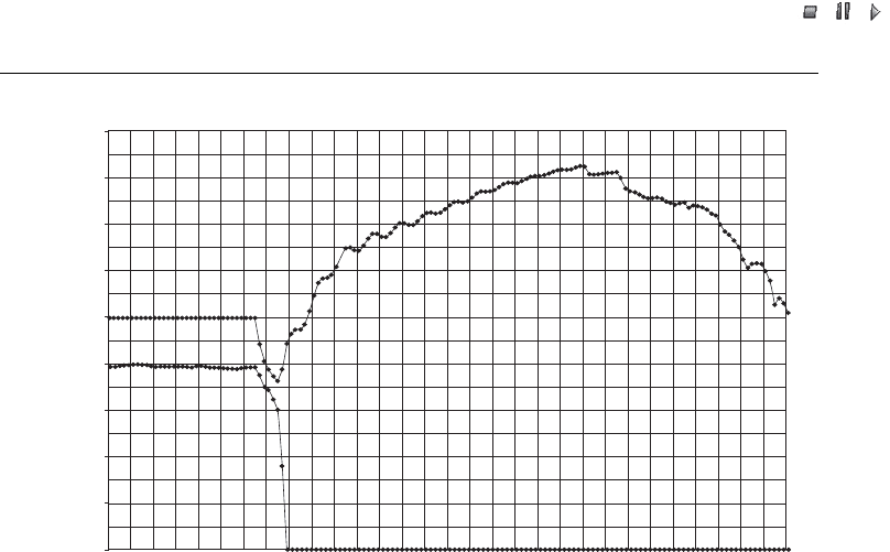
There are other significant issues that must also be addressed with respect to island-
ing, and one of the consequences of detail oversight is shown in Figure 12.7. There,
slow-acting medium-voltage vacuum breakers acted slowly and left VAR support on an
island for far too long. When the energy transfer stopped, this resulted in a substantial
overvoltage condition.
Good protection and a reasonably rapid speed of response to such conditions is
important. Generally, 0.2 to 0.3 seconds is an adequate and effective time to clear
VAR support in the event of an island, and in the event illustrated in Figure 12.7 would
have prevented such an overvoltage condition.
274 Wind Power on Weak Grids
//INTEGRAS/KCG/P AGIN ATION/ WILEY /WPS /FINALS_1 4-12- 04/0470855088_ 13_CHA12 .3D – 275 – [257–282/26]
20.12.2004 7:43PM
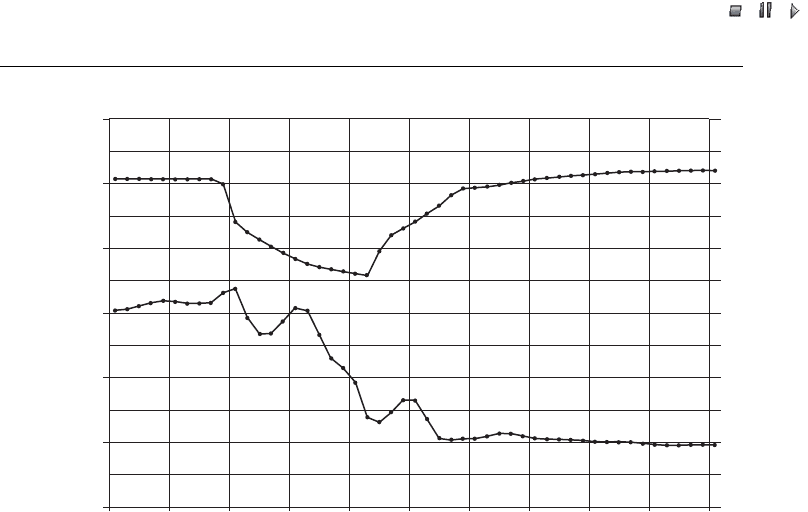
12.3.10 Self-correcting fault condition: VAR starvation
The self-correcting concept associated with an unstable line or overloaded grid has been
used by planners as a fall-back technique to avoid the need to upgrade facilities to
handle maximum generation. Such cond itions are commonly associated with Type A or
B wind turbines, and the limited VAR support associated with standard wind turbine
controllers, and overall system inadequate VAR support compared with need. Wind
turbine controllers have historically been set with grid-protection settings that are close
to nominal voltage and fast acting. The result has been that, as a voltage collapse event
starts to occur, and most such events develop slowly, over a period of some seconds,
a significant number of wind turbines will sense low voltage and drop off the grid prior
to the collapse fully cascading. As the wind turbines drop off the grid, and if they are
consuming VARs, the result is a reduction in VAR consumption and a restoration of
grid stability. Figure 12.8 is an example of this condition.
The self-correcting technique does prevent a cascading voltage collapse event due to
VAR starvation. It still causes substantial served load grief, though, and is not a good
approach for reliable grid operation. Critical served load is also voltage sensitive and
also trips at or before the wind turbines trip to clear the condition. This is a condition
caused not by the wind turbines, but by inadequate VAR support, and the latter is the
condition that should be properly corrected. In the Tehachapi area, such behaviour has
caused economic loss to served load, and improved VAR support and/or improved grid
facilities are the proper and economically correct solution. The improved VAR support
U
U
P
0123456
Time (s)
1.8
1.6
1.4
1.2
1.0
0.8
0.6
0.4
0.2
0.0
Per unit voltage, U
Per unit active power, P
P
Figure 12.7 Islanding event: overvoltage impacted by slow operating controls for a short period.
Note: Figure 12.9 is of the same event; at that facility the event was handled without significant
consequence. On the island, the excess VARs caused the Type A or B induction machines to
overexcite and climb to the maximum of their saturation curve until the condition cleared
Wind Power in Power Systems 275
//INTEGRAS/KCG/P AGIN ATION/ WILEY /WPS /FINALS_1 4-12- 04/0470855088_ 13_CHA12 .3D – 276 – [257–282/26]
20.12.2004 7:43PM
provided by wind farms in recent years has dramatically reduced the occurrence of
events such as this, but more could readily be done.
The best new practices for interconnecting wind turbines can readily provide the
capability for wind farms to add valuable VAR support to the grid and avoid this sort
of problem and to otherwise become at least as good as a synchronous generator in
providing grid reliability.
Speed of response for VAR control in such a VAR starvation event can be in the
order of a few seconds to catch and correct the event. Thus, controls designed for fast
enough performance to handle a critical islanding event would be more than fast enough
to effectively handle VAR starvation events.
The behaviour of grid vo ltage in a typical grid instability situation is of similar speed,
and corrective controls responding in 0.2 to 0.3 seconds can provide excellent dampen-
ing of the oscillation when voltage-responsive.
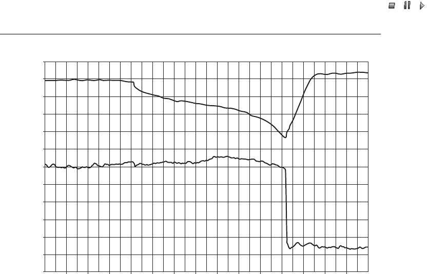
12.3.11 Higher-speed grid events: wind turbines that stay connected
through grid events
Some grid events, such as the one shown in Figure 12.9 are fast developing and require a
different speed of response, or a different approach, to respond effectively to and impact
the event. In this event, there is more than a 10 % dro p in voltage in about 0.05 s and
a nearly 30 % drop in 0.50 s.
U
U
P
P
0 2 4 6 8 10 12 14 16 18 20 22 24 26 28 30
1.0
1.1
0.9
0.8
0.7
0.6
0.5
Per unit voltage, U
Per unit active power, P
Time (s)
Figure 12.8 Self-correcting feature: VAR starvation grid collapse, self-correcting by WT drop
off line
276 Wind Power on Weak Grids
//INTEGRAS/KCG/P AGIN ATION/ WILEY /WPS /FINALS_1 4-12- 04/0470855088_ 13_CHA12 .3D – 277 – [257–282/26]
20.12.2004 7:43PM
In this wind farm, there are two types of Type A wind turbines. One group consists of
reasonably new repower wind turbines, and they tripped offline in approximately 0.2 s
after the event exceeded their grid limits, as they should have done, according to their
specifications. The other group consists of older Type A wind turbines but with a unique
control system. That group nicely stayed online through the event and continued to
deliver energy to the grid without interruption, as would a reliable synchronous gen-
erator. Interestingly, wind turbines e quipped with ride-through capability according to
usual standards would also have ridden through this event.
Thus, there are two potential ways in which a wind turbine and wind farm can respond
to fast events such as this one. One is by use of very fast acting VAR support.
A substantial magnitude of VARs would be required to impact this event materially to
keep it below a 10 % drop in voltage. This is possible, but may neither be practical nor
desirable as a standard approach. From Figure 12.4 one can see that 1.2 p.u. VARs would
not be capable of keeping the voltage to even a 15 % transient drop inside the wind farm.
Interestingly, it could do so if all wind farms on the weak grid were able to respond
effectively. However, the more appropriate technique is to ride through the event and, in
so doing, maintain continuity and reliability of generation. Clearly, new wind turbines
effectively equipped can ride through such events, but older wind turbines can also be
reasonably equipped to ride through common short-duration events such as the one
illustrated in Figure 12.9, provided there is commensurate value in their doing so.
FACTS devices, as well as Type C and D wind turbines equipped with responsive
VAR control, and Type A and B wind turbines eq uipped with fast thyristor VAR
control, are all capable of providing an effective contribution to minimiz e events such
U
U
P
P
Time (s)
1.200
1.000
0.800
0.600
0.400
0.200
0.000
0.00 0.20 0.40 0.60 0.80 1.00 1.20 1.40 1.60 1.80 2.00
Per unit voltage, U
Per unit active power, P
Figure 12.9 The transient event illustrated in Figure 12.7: in this case, the wind farm did not
island but instead recovered well; voltage dip can be reduced by fast-acting VAR support
Wind Power in Power Systems 277

//INTEGRAS/KCG/P AGIN ATION/ WILEY /WPS /FINALS_1 4-12- 04/0470855088_ 13_CHA12 .3D – 278 – [257–282/26]
20.12.2004 7:43PM
as the one shown in Figure 12.9. However, it is clear that substantial VA Rs are required
to assist materially in such an event, and the alternative of ride-through capability
appears to be of better value for dealing with such events. When one considers the
balance of grid needs, and the way reliability standards work, it seems that somewhat
slower, but automatic, VARs combined with ride-through capability would provide
essentially the full needs of most grid situations and would be consistent with a cost-
effective capability that could be provided by wind turbines and wind farms (see the
comments on automa tic VAR control in Section 12.3.12).
12.3.12 Use of advanced VAR support technologies on weak grids
Conventional VAR support has historically been provided from the controlled over-
excitation of synchronous machines, improving such performance and behaviour
through voltage regulators and power system stabilizers. Longer transmission lines
and grid segments remote from such generation have used switched capacitors for added
VAR support to the extent needed to maintain voltage within limits and to maintain
a stable grid. The evolution of various FACTS devices and similar technology has
brought the same performance advantages of advanced conventional VAR support to
the distributed environments where capacitors have been used historically (Muljadi
et al., 2004).
A very early FACTS device used in association with wind turbines and wind farms
was the 1991 installation of an ABB SVC in Tehachapi on the SCE grid in the Varwind
substation. This device was initially installed at 9.6 MVAR and increased later to
14.4 MVAR. It is composed of 12 steps of transient-free thyristor-switched capacitors,
dampening inductors and tw o steps of transformers. An attempt to add one or two steps
of 5 kVAR slow-switched capacitors was not successful because of unresolved resonance
issues. This device has at least the capability of voltage control, and observed data have
shown that it performs very well in improving grid stability and regulation at the critical
node where it is located. However, it clearly has had problems resulting from resonance
issues and has been rebuilt at least once. From what can be learned, the resonance issues
are severe at low energy flows on the grid. Even the substantial impedance provided in
its design was not sufficient to limit harmonic currents adequately during certain low-
energy flow conditions, and internal damage resulted from such operation. From these
lessons it seems that there is a significant advantage to the fully distributed VAR
support model of Figure 12.4 where a single step of operation can be de vised for
each node that is nicely damped by efficient use of available system components
and where those components inherently provide a relatively high per unit impedance
at low cost.
Comparable technology to FACTS was developed in the Type D wind turbines of
Kenetech, with an installation of 112 turbines of 35 MW in Culbertson County Texas in
1995. There, the VAR support capability of the integrated gate bipolar transformers
(IGBT) controllers of these wind turbines materially contributed to the grid stability of
a weak grid. The grid in that area was further saturated in 1999 with the addition of
30 MW of Type C turbines with similar capabilities. The combined enhanced VAR
capability of these facilities resulted in their successful operation.
278 Wind Power on Weak Grids

//INTEGRAS/KCG/P AGIN ATION/ WILEY /WPS /FINALS_1 4-12- 04/0470855088_ 13_CHA12 .3D – 279 – [257–282/26]
20.12.2004 7:43PM
At about the same time, several large wind farms were developed in the Lake Benton
area of southwestern Minnesota involving similar Type C and Type D turbines and with
a similar set of weak-grid problems. Enhanced VAR support provided by these turbines
was extensively evaluated by the National Renewable Energy Laboratory (NREL) and
the effectiveness of significant performance features is well reported. These evaluations
confirm the significant performance advantage of voltage-regulated VAR controls in
resolving grid-support and stability problems (Muljadi, Wan and Butterfield, 2002).
A transient-free thyristor-controlled switched-capacitor 1.1 MVAR low-cost distrib-
uted VAR support installation was tested in Tehachapi, integrated with the facilities of a
megawatt size wind turbine. This unit demonstrated technology for a large virtual SVC-
type FACTS device that is modular and of substantial potenti al capacity based on the
size of the wind farm. It is capable of being integrated with a wind farm, centrally
controlled through fast-acting distributed control. This arrangement appears to have
important harmonic and cost advantages.
FACTS devices constructed in a modular factory built containerised design have been
installed and operated successfully to resolve weak grid problems at Foote Creek,
Wyoming and Minot, North Dakota. These D-VA R
tm
units utilize an IGBT converter
and capacitors providing fast response and generally stepless control of both VAR
production and VAR consumption. A further advantage of these particular FACTS
devices is that they provide full range control of VARs over a broad voltage range, and
thus have superior VAR support capability during a transient event. Capacitors con-
nected directly to the grid do not have this two quadrant capability, and their VAR
production decreases as the square of the voltage. The IGBT arrangement, on the other
hand, provides for the VARs to decrease only at the first power of voltage. The IGBT
converters associated with Type C and D WTs have similar first power of voltage VAR
support, and the ability to both deliver and consume VARs. WFs with Type A and B
WTs and switched capacitor VAR support also have the inherent capabil ity for wide
range production and consumption of VARs since with all of the capacitors turned off,
the WTs and WF collection system consume substantial VARs and can be controlled for
a wide two quadrant range of control.
12.3.13 Load flow studies on a weak grid and with induction machines
One might wonder why the weak grid areas of California, Minnesota and Texas would
have such a difficult time anticipating and resolving the substantial grid capacity and
stability issues that have caused such great problems for the utilities, grid customers and
the wind industry. A significant factor has been that the models used for load flow
studies and transient stability studies simply did not correctly represent induction
machines and their impact on the grid. A related facto r is that VAR transport issues
were not understood by the utilities, and they attempted to maintain self control over
VARs and to supply known needed VARs from afar, with poor resul ts. Until the mid-
1990s, wind farms were installed by only two utilities in the USA, and Tehachapi was
the only large installation with a weak grid. Thus, the problem was not widespread
nationally and, until relatively recently, there simply was a lack of attention to the issue
first seen in Tehachapi.
Wind Power in Power Systems 279

//INTEGRAS/KCG/P AGIN ATION/ WILEY /WPS /FINALS_1 4-12- 04/0470855088_ 13_CHA12 .3D – 280 – [257–282/26]
20.12.2004 7:43PM
In the late 1990s a local College math department did studies of the problem with
induction machines on the grid and provided helpful insight. NREL played an extensive
role in evaluating the Type C and D wind turbine installations and, as a part of that effort,
developed substantial documentation and understanding of the issues. The providers of
PSS/E
TM(1)
and PSLF (general electric positive sequence load flow) load flow programs
have recently expended substantial efforts, and their programs have been dramatically
improved to handle induction machines and specific wind turbine designs with built-in
models. Thus, it appears that a great deal of the technical difficulty of predicting wind
turbine, wind farm and grid behaviour may finally be becoming resolved with good tools.
12.4 Private Tehachapi Transmission Line
In 1989 two developers and a consortium of project entities, with 185 MW of stranded
unbuilt PPA capacity from the 1985 contracts, elected to build their own private transmis-
sion line to carry the new generation out of Tehachapi to the major 500 kV Vincent
substation in order to be able to deliver energy from those projects. Another 135 MW of
operating PPA capacity on the 66 kV system that was being heavily curtailed was moved
to the new private line, for a total installed capacity of 320 MW. This step relieved major
curtailment payments and increased economic certainty. This private line is 100 km in
total length and was constructed at 230 kV. It has proven to be extremely successful.
The Sagebrush Line at 230 kV, and of approximately similar connected capacity as the
SCE 66 kV network, serves as a dramatic comparison, showing what the utility grid could
be. Although the Sagebrush Line is considered by the utility to be lower-cost construction,
it has performed extremely well and reliably – far more so than the utility grid. The
Sagebrush Line has important reliability features that are missing from the 66 kV grid,
such as an overhead static ground line that provides substantial lightning protection and
good physical protection against vehicle and fire damage, which have so impacted the 66 kV
grid. The monitoring and control capabilities of the Sagebrush Line are excellent and
provide operators with key operating data that would be most useful on the 66 kV network.
There are limitations to the use of the line. The organizational structure used to allow
the private line legally to be built and operated has effectively precluded the addition of
additional generators onto the line and prevents use of the line for served customer load.
Metering of energy deliveries is based on deliveries at the distant end of the line and thus
the generators must absorb approximately 5 % energy losses associated with the line. The
line is now 15 years old, and some of the organizational limitations are beginning to be
resolved, and the prospect exists for the line to become more widely available for more
general use. 60 MW new generation is under construction, soon to be added onto the line,
increasing its connected generation to approximately 380 MW, with a prospect for further
increased use of the line.
The techniques used to facilitate rapid development and low-cost construction of
the line are noteworthy. California utilities have eminent domain rights and can
readily acquire rights of way for transmission lines. However, such is not the case
(1)
Power System Simulation for Engineers; a registered trademark of PTI.
280 Wind Power on Weak Grids