Adlard E.R. (ed.) Chromatography in the Petroleum Industry
Подождите немного. Документ загружается.

Chapter
7
lo000
lo00
100
10
10'
10'
-
F=1/31
F=l/lI
F=
1/46
F=
112.7
-__-
---
....
-
.....
Slit
width
JJITI
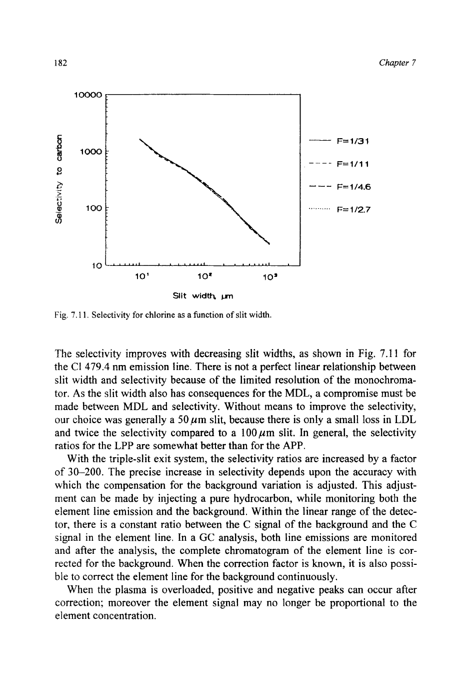
Fig.
7.1
1.
Selectivity
for
chlorine
as
a
function
of
slit
width.
The selectivity improves with decreasing slit widths, as shown in Fig.
7.1
1
for
the C1479.4 nm emission line. There is not a perfect linear relationship between
slit width and selectivity because of the limited resolution
of
the monochroma-
tor.
As
the slit width
also
has consequences for the
MDL,
a compromise must be
made between MDL and selectivity. Without means to improve the selectivity,
our
choice was generally a 50pm slit, because there
is
only a small loss in LDL
and twice the selectivity compared to a l00pm slit. In general, the selectivity
ratios for the
LPP
are somewhat better than for the
APP.
With the triple-slit exit system, the selectivity ratios are increased by a factor
of
30-200.
The precise increase in selectivity depends upon the accuracy with
which the compensation
for
the background variation is adjusted. This adjust-
ment can be made by injecting a pure hydrocarbon, while monitoring both the
element line emission and the background. Within the linear range
of
the detec-
tor, there is a constant ratio between the
C
signal of the background and the
C
signal in the element line. In a
GC
analysis, both line emissions are monitored
and after the analysis, the complete chromatogram
of
the element line is cor-
rected for the background. When the correction factor
is
known, it is also possi-
ble to correct the element line for the background continuously.
When the plasma is overloaded, positive and negative peaks can occur after
correction; moreover the element signal may no longer be proportional to the
element concentration.

TABLE
7.6
PERFORMANCE
OF PLASMA
DETECTORS
Element Line Low-pressure plasma Atmospheric-pressure plasma
(nm)
MDL MDL Sel. Sel. LDR
MDL
h4DL
Sel.
Sel.
LDR
(ppm)
(PP/s)
uric-
xl000 xl000
(ppm)
(pgk)
un-
x
1000
x
1000
con.
corr.
corr.
con.
C
241.8
0.006
1
.o
-
-
300
0.003 0.5
-
-
60
193.1
0.001
0.2
-
-
1000 0.001 0.2
-
-
200
H
656.2
0.008
0.1
800
80
(200) 0.03
0.4
270
I0
(20)
486.1
0.04
0.6 250 20 (40) 0.17
2.4 70 20 (4)
D
656.4
0.008
0.2 600
50
(200) 0.04 1.1 100 10
0
771.2 0.13 29 40
0.038
8.4 10
N
146.9 0.13 25 1300 10 40 0.3
58
750 10 2
CI
479.5
0.009
4.4 940 100 100 0.012 5.9 950 100
8
Br
470.5 0.006 6.7 1600 40 200 0.005 5.6 620 20 20
I
516.1
0.008
14 1040 40
200
0.004 7.1 210 20 20
F
685.6 0.07 19 740
0.08
22 400
S
545.4
0.05
22 180 20 20 0.06 21 120
10
1
180.7 0.01 4.5 850
80
100 0.01 4.5
500
30
5
Hg
365.0 0.0002 0.6 105 >lo00 1000 0.0001 0.2 105 >loo0 1000
Ar
750.3
0.03
17 2900 100 0.2 100 100 7
Kr
473.8 0.03 40 460 20 50 0.15 160 140 10 4
Xe
529.2
0.008
13 4200 100
80
0.025 29 1200 100 3
Ne
640.2 0.05 14 540 50 100 0.06 17 460
30
87
e
8
184
Chapter
7
7.5
CONCLUSIONS
Table
7.1
presents the conditions used for the evaluation of both types of
plasma. A summary
of
the results
is
given in Table
7.6.
For
comparison, for the
MDL, the results are also given in pg/s. From these results, we may draw the
following conclusions:
1.
The
MDLs
for both types of plasma are the same. The
MDLs
are between
0.1
and 100 pgs, depending on the element to be measured and on the in-
tensity of the emission line used. The MDLs of the atmospheric plasma are
almost the same as the data presented by Quimby
et
al.
[23].
2.
In
order to obtain the same
MDLs,
the light-collecting system of the low-
pressure plasma must be better and
is
more expensive.
3.
The maximum concentration that can be introduced into the low-pressure
plasma is about ten times that
of
the atmospheric plasma.
4.
The linear dynamic range is between
lo3
and
lo5
for the atmospheric- plasma
and between
lo4
and
5
X
lo5 for the low-pressure plasma.
5.
The selectivity ratio with respect to carbon is about the same for both plas-
mas and ranges from
100
up
to
2000
without a correction system in use. With
corrections (triple-slit system) the selectivity ratios relative to carbon are
between
lo4
and
lo6.
6.
Because of the good sensitivity and very short. response times, both types of
plasma detectors are well suited for use with capillary gas chromatographic
columns.
7.6
DESCRIPTION OF THE HEWLETT PACKARD
5921A
AED
Apart from the plasma emission detectors described in the previous
paragraphs, supplied by Applied Research Laboratories, and then by Applied
Chromatographic Systems, a number of other plasma emission detectors
have been announced by other instrument manufacturers. At the 1989 capil-
lary chromatography symposium in Riva del Garda, Italy, the Varian Instru-
ment Group (Walnut Creek, CA,
USA)
announced an atomic emission detector
[27]
and in May 1990 Carlo Erba Instruments (Rodano, Italy) announced their
plasma emission detector ESD-4
[28]
but to the time of writing, these detectors
have
not
been released. The only plasma detector that is commercially available
at present is the Hewlett Packard (Avondale, PA,
USA)
HP
5921 atomic emis-
sion detector (AED) and this instrument is described
in
more detail in the next
sections.
Microwave plasma detectors
185
7.6.1
Gas chromatograph and transfer line
The gas chromatograph most convenient for coupling to the AED is the
HP
5890A series
I1
adapted with a transfer line between
GC
and the AED cavity. It
has a mode of monitoring and controlling the flow through the column by pres-
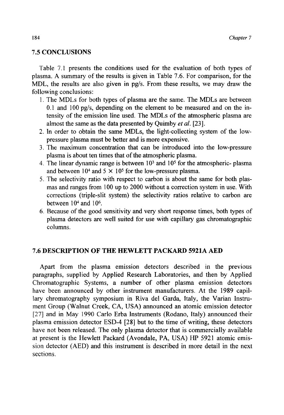
sure programming. The complete set-up
of
this
GC
and
AED
is
depicted in Fig.
7.12.
Since the AED is a concentration-type detector, this constant flow mode of
operation is mandatory for quantitative work. The transfer line consists
of
1.5 m
of heated and insulated outer aluminium tube, with an inner tube of stainless
steel with an i.d. just over 1 mm,
so
that it heats the analytical column inside
properly. Since heating up this transfer line is a rather slow process, it should be
kept continuously at maximum column temperature. Up to the normal operating
temperature of
300"C,
no specific measures have to be taken. In high-
temperature
GC,
however, where temperatures far over
300°C
are quite com-
mon, the limit of the temperature specification (which is
400°C)
is reached for
the transfer line. Neither polyimide-coated fused silica columns, nor aluminium-
clad columns can withstand these temperatures for more than
2
days (which is
50 h continuously). The only columns capable of being bent (to be pushed
1
-
In
I
LJ
I
I
I
I
I\
2
3
4
5
\'
L
7
I-
I
I
I
I
I
I----
I
__-
I
--A
I
6
I
1
I
I
I
/r
!TI;
Fig.
7.12.
Diagram
of
the Hewlett Packard GC-AED:
(1)
autosampler;
(2) GC;
(3)
capillary col-
umn;
(4)
transfer line;
(5)
cavity;
(6)
magnetron; (7) spectrometer;
(8)
water cooling pump;
(9)
cavity
gas
control;
(10)
computer.
References
D.
200
186
Chapter
7
through the transfer line) which can withstand these temperatures for a long pe-
riod of time are stainless-steel high-temperature columns. Experiments have
shown that these columns only have to be replaced after
1
month of operation.
This means that the last
1.5
m
of
the column has been at
400°C
for
700
h
con-
tinuously! These columns are available from Chrompack, Middelburg, The
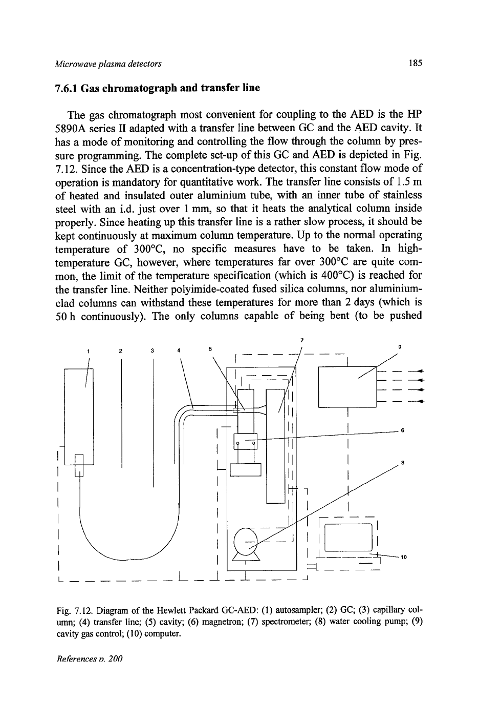
Netherlands. The gas union
of
the cavity, which
is
the exit of the column to the
detector, as is shown in Fig.
7.13,
has an i.d.
of
0.75 mm, since it was designed
for acceptance
of polyimide capillary columns. The steel capillary columns,
however, have an 0.d. of
0.8
mm,
so
the gas union should be drilled out to about
0.9
mm to accept these columns.
Fig.
7.13.
The
HP
atomic emission detector:
(1)
plasma;
(2)
capillary column;
(3)
make-up and
reagent gasses in-out, solvent vent;
(4)
discharge
tube;
(5)
cooling water;
(6)
microwave energy in;
(7)
optical window;
(8)
window purge;
(9)
O-ring;
(10)
heated zone;
(1
1)
spectrometer.
Microwave plasma detectors
187
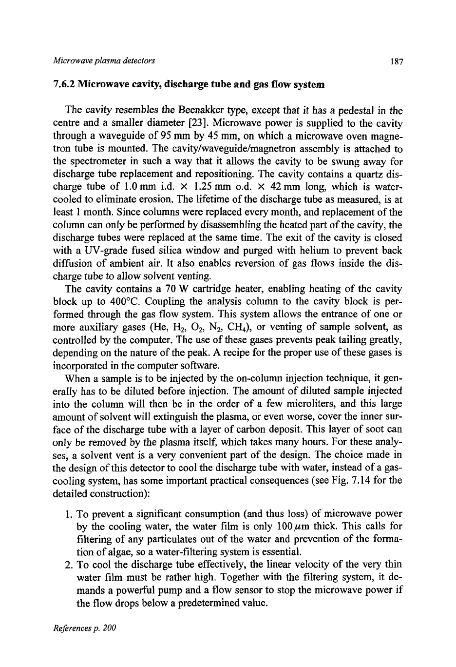
7.6.2
Microwave cavity, discharge tube and gas flow system
The cavity resembles the Beenakker type, except that it has a pedestal in the
centre and a smaller diameter
[23].
Microwave power is supplied to the cavity
through a waveguide of
95
mm by
45
mm,
on which a microwave oven magne-
tron tube is mounted. The
cavity/waveguide/magnetron
assembly is attached to
the spectrometer in such a way that it allows the cavity to be swung away for
discharge tube replacement and repositioning. The cavity contains a quartz dis-
charge tube of
1.0
mm
i.d.
X
1.25
mm 0.d.
X
42
mm
long, which is water-
cooled to eliminate erosion. The lifetime of the discharge tube as measured, is at
least
1
month. Since columns were replaced every month, and replacement of the
column can only be performed by disassembling the heated part of the cavity, the
discharge tubes were replaced at the same time. The exit of the cavity is closed
with a UV-grade fused silica window and purged with helium to prevent back
diffusion of ambient air. It also enables reversion of gas flows inside the dis-
charge tube to allow solvent venting.
The cavity contains a
70
W
cartridge heater, enabling heating of the cavity
block up to 400°C. Coupling the analysis column to the cavity block is per-
formed through the gas flow system. This system allows the entrance of one or
more auxiliary gases (He,
H2,
02,
N2,
CH,),
or venting of sample solvent, as
controlled by the computer. The use of these gases prevents peak tailing greatly,
depending on the nature
of
the peak.
A
recipe for the proper use of these gases is
incorporated in the computer software.
When a sample is to be injected by the on-column injection technique, it gen-
erally has to be diluted before injection, The amount of diluted sample injected
into the column will then be in the order of a few microliters, and this large
amount of solvent will extinguish the plasma, or even worse, cover the inner sur-
face of the discharge tube with a layer of carbon deposit. This layer of soot can
only be removed by the plasma itself, which takes many hours. For these analy-
ses, a solvent vent is a very convenient part of the design. The choice made in
the design of this detector to cool the discharge tube with water, instead of a gas-
cooling system, has some important practical consequences (see Fig.
7.14
for the
detailed construction):
1.
To
prevent a significant consumption (and thus loss)
of
microwave power
by the cooling water, the water film is only 100,um thick. This calls
for
filtering of any particulates out of the water and prevention of the forma-
tion of algae,
so
a water-filtering system is essential.
2.
To
cool the discharge tube effectively, the linear velocity of the very thin
water film must be rather high. Together with the filtering system, it de-
mands a powerful pump and a flow sensor to stop the microwave power if
the flow drops below a predetermined value.
References
p.
200
I88
Chapter
7
It
12
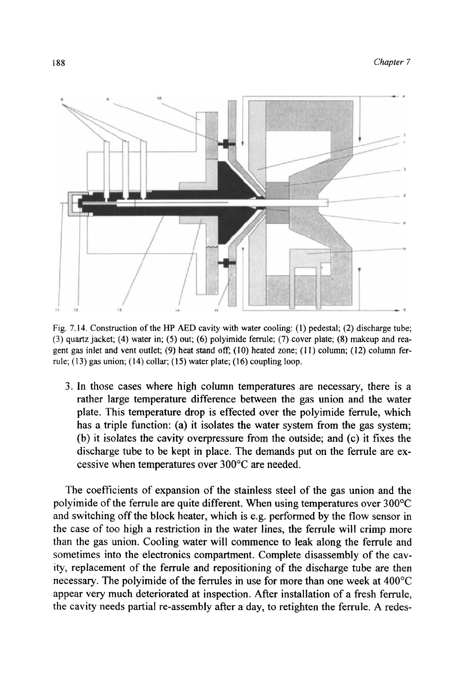
Fig.
7.14.
Construction of the
HP
AED
cavity with water cooling:
(1)
pedestal;
(2)
discharge tube;
(3)
quartz
jacket;
(4)
water in;
(5)
out;
(6)
polyimide ferrule;
(7)
cover plate;
(8)
makeup and rea-
gent
gas
inlet and vent outlet;
(9)
heat
stand
0%
(10)
heated zone;
(1
l)
column;
(12)
column
fer-
rule;
(1
3)
gas union;
(1
4)
collar;
(1
5)
water plate;
(16)
coupling loop.
3.
In
those cases where high column temperatures are necessary, there is a
rather large temperature difference between the gas union and the water
plate. This temperature drop is effected over the polyimide ferrule, which
has a triple function: (a) it isolates the water system from the gas system;
(b) it isolates the cavity overpressure from the outside; and (c) it fixes the
discharge tube to be kept in place. The demands put on the ferrule are ex-
cessive when temperatures over 300°C are needed.
The coefficients of expansion of the stainless steel of the gas union and the
polyimide
of
the ferrule are quite different. When using temperatures over
300°C
and switching off the block heater, which is e.g. performed by the flow sensor in
the case of too high a restriction
in
the water lines, the ferrule will crimp more
than the gas union. Cooling water will commence to leak along the ferrule and
sometimes into the electronics compartment. Complete disassembly of the cav-
ity,
replacement of the ferrule and repositioning of the discharge tube are then
necessary. The polyimide of the ferrules in use for more than one week at
400°C
appear very much deteriorated at inspection. After installation of a fresh ferrule,
the cavity needs partial re-assembly after a day, to retighten the ferrule. A redes-
Microwave
plasma
detectors
189
ign of this part of the detector for high-temperature work should therefore be
considered.
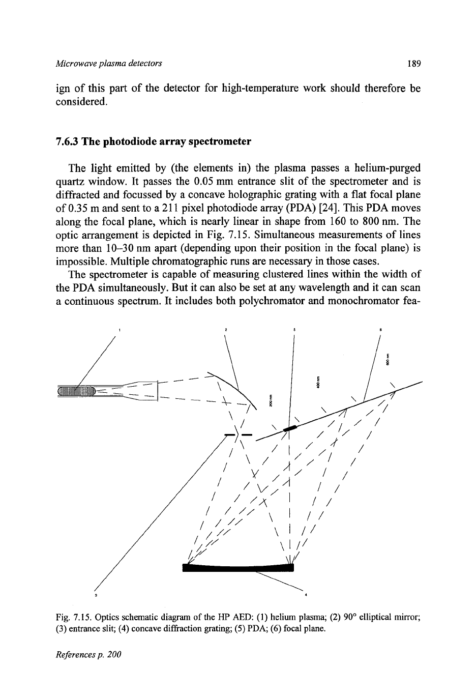
7.6.3
The photodiode array spectrometer
The light emitted by (the elements in) the plasma passes a helium-purged
quartz window. It passes the
0.05
mm entrance slit of the spectrometer and is
diffracted and focussed by a concave holographic grating with a flat focal plane
of
0.35
m and sent to a
21
1
pixel photodiode array (PDA)
[24].
This PDA moves
along the focal plane, which is nearly linear in shape from
160
to
800
nm. The
optic arrangement is depicted in Fig.
7.15.
Simultaneous measurements
of
lines
more than
10-30
nm apart (depending upon their position in the focal plane) is
impossible. Multiple chromatographic runs are necessary in those cases.
The spectrometer is capable
of
measuring clustered lines within the width of
the PDA simultaneously. But it can also be set at any wavelength and
it
can scan
a continuous spectrum. It includes both polychromator and monochromator fea-
Fig.
7.15.
Optics schematic diagram
of
the
HP
AED:
(1)
helium plasma;
(2)
90'
elliptical mirror;
(3)
entrance slit;
(4)
concave diffraction grating;
(5)
PDA,
(6)
focal plane.
References
p.
200
190
Chapter
7
tures. The spectrometer itself is heavily thermally insulated and since wave-
length correction is performed at the start of each chromatographic run, it means
that the thermal time constant of wavelength precision
is
in excess of
20
h. The
cavity
is
attached to the outside wall of the spectrometer,
so
that the focus of the
elliptical mirror
is
2
mm
into the end
of
the discharge tube. The 21
1
detecting
elements of the PDA are all active
100% of the time,
so
that signal and back-
ground portions next to a spectral line are continuously measured and corrected
for.
7.6.4
Computerized control and data treatment
The gas chromatograph as well as the AED is computer controlled with a HP
35920A
GC-AED Chemstation. All functions of the system can be performed by
softkey control. Correct scavenger gases are automatically turned on, and the
required order sorter (optical filter) is chosen. It automatically calibrates the
AED
for
wavelength determinations before each run.
To locate the atomic line centres with the PDA precisely, the centre of gravity
calculation algorithm
[29] is used.
For
most atomic lines, it results in a standard
deviation of the estimation of the line centre better than
0.01
pixel. The helium
spectrum provides several narrow, intense lines most suited as wavelength stan-
dards. The auxiliary gases provide small amounts of carbon, nitrogen, hydrogen
or oxygen, which also can be used as calibration lines. The mechanical position
of
the PDA on the focal plane is converted to nominal wavelength (which is very
close
to
linear), using a numerical model of the spectrometer. Since selectivity
of
non-metallic elements
in
atomic emission spectroscopy relative to carbon rarely
exceeds
a
few hundred, background correction is necessary to improve this. An
improvement by several orders of magnitude is obtained by means of real-time
multipoint background correction. See also Table
7.7.
The PDA read-out time is usually 10
Hz,
but sometimes
100
Hz
is used during
calibration routines. Signals specific for
an
element are produced by a computer-
induced “recipe”, composed of a pair of linear functions of the various pixel sig-
nals.
In
this recipe, pixel responses, element filter and background signal are re-
corded,
so
that the calculated background amount to give optimal selectivity can
be
ad-justed post-run.
7.6.5
Characteristics
The sensitivities and the selectivities of the various elements depend on the
element line used for measurement.
A
number of common elements on which we
Microwave
pfasma
detectors
191
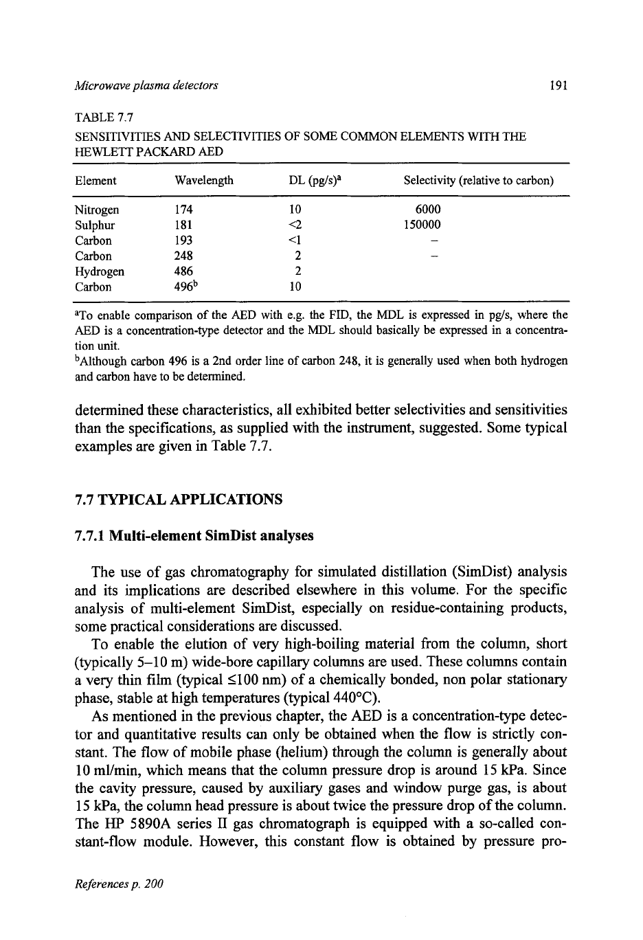
TABLE 7.7
SENSITIVITIES
AND
SELECTIVITIES
OF
SOME
COMMON ELEMENTS WITH
THE
HEWLE'IT PACKARD AED
~ ~~
Element Wavelength DL (Pma Selectivity (relative to carbon)
Nitrogen 174 10
Sulphur 181 <2
Carbon 193 <1
Carbon 248 2
Hydrogen 486 2
Carbon 496b 10
6000
150000
aTo enable comparison
of
the
AED
with e.g. the FID, the MDL is expressed in pg/s, where the
AED
is a concentration-type detector and the MDL should basically be expressed in a concentra-
tion unit.
bAlthough carbon 496 is a 2nd order line
of
carbon 248, it is generally used when both hydrogen
and
carbon have to be determined.
determined these characteristics, all exhibited better selectivities and sensitivities
than the specifications, as supplied with the instrument, suggested. Some typical
examples are given in Table
7.7.
7.7
TYPICAL APPLICATIONS
7.7.1
Multi-element
SimDist
analyses
The use of gas chromatography for simulated distillation (SimDist) analysis
and its implications are described elsewhere in this volume. For the specific
analysis
of
multi-element SimDist, especially on residue-containing products,
some practical considerations are discussed.
To enable the elution
of
very high-boiling material from the column, short
(typically 5-10 m) wide-bore capillary columns are used. These columns contain
a very thin film (typical 1100 nm)
of
a chemically bonded, non polar stationary
phase, stable at high temperatures (typical
44OOC).
As
mentioned in the previous chapter, the AED is a concentration-type detec-
tor and quantitative results can only be obtained when the flow is strictly con-
stant. The
flow
of
mobile phase (helium) through the column
is
generally about
10
ml/min, which means that the column pressure drop is around 15 Pa. Since
the cavity pressure, caused by auxiliary gases and window purge gas, is about
15
Ha, the column head pressure is about twice the pressure drop of the column.
The
HP
5890A
series
II
gas chromatograph is equipped with a so-called con-
stant-flow module. However, this constant flow
is
obtained by pressure pro-
References
p.
200