Ahmed S.N. Physics and Engineering of Radiation Detection
Подождите немного. Документ загружается.

406 Chapter 6. Scintillation Detectors and Photodetectors
Just like conventional photodiode detectors, the avalanche photodetectors can
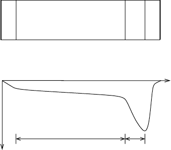
also be designed and built in different configurations. Fig.6.5.23(a) shows the con-
ceptual design of a simple avalanche photodetector. The detector is made of an
intrinsic (or lightly doped p type material) sandwiched between a heavy doped p
side and a heavy doped n side. Another p type region is also established between
the intrinsic material and the heavily doped n side. The contacts are made by metal
deposition on two sides of the detector. A high reverse bias applied at the two ends
creates an electric field profile similar to the one sketched in Fig.6.5.23(b). Based on
this electric field profile two regions can be identified: an absorption region R
abs
and
a multiplication region R
mult
. The incident radiation passing through the intrinsic
or absorption region creates electron hole pairs along its track. The charges move
in opposite directions under the influence of moderate electric field inside R
abs
.The
electrons move towards the p region, which is characterized by very high electric
field intensity. This is where avalanche multiplication takes place. The large num-
ber of electron hole pairs generated here, as a result of charge multiplication, move
in opposite directions and induce a voltage pulse that is measured by the readout
electrode. Alternatively the current generated by the motion of charges can also be
measured by the associated electronics.
mult
R
abs
R
n
+
+
p
V
(b)
π
p
(a)
Figure 6.5.23: (a) Conceptual design of
a simple avalanche photodetector. (b)
The electric field profile of the struc-
ture shown in (a). π represents either a
lightly doped p-material or intrinsic ma-
terial while the superscript (+) refers to
heavy doping.
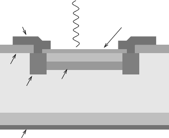
The kind of structure shown in Fig.6.5.23 is generally known as reach-through
structure. Fig.6.5.24 shows the practical design of a reach-through APD. The guard
ring around the multiplication region is established to minimize the possibility of
electrical breakdown.
C.1 Basic Desirable Characteristics
The desirable characteristics of an avalanche photodetector are not much different
from the conventional photodiode detectors as can be deduced from the list below.
Small Leakage Current: An idea APD does not have any leakage current.
Real APDs have extremely small dark currents. The reason to strive for no
leakage current is to avoid unwanted avalanches, something that may induce
non-linearity in the detector response.
6.5. Photodetectors 407
p+
n+
n
Intrinsic
Guard Ring
SiO
2
Metal Contact
Antireflective Coating
p
Metal Contact
Photon
Figure 6.5.24: Typical structure of a sili-
con based reach-through type avalanche
photodetector.
High Gain: Since the sensitivity of the detector depends on its gain therefore
the APDs are designed such that they have gains of up to 10
8
. However de-
pending on the application, one can opt for lower gain, which can be achieved
by applying lower electric field.
Good Frequency Response: Good frequency response is one of the most
desirable characteristics of APDs, specially the ones that are to be used in high
rate environments.
It should be noted that the last two characteristics are similar to the ones desired
in photomultipliers, which of course is not a surprise since both detectors have essen-
tially the same purpose. We will shortly see that modern APDs have characteristics
near to their ideal values.
C.2 Multiplication Process and Gain Fluctuations
The process of electron multiplication in an APD is very much different from the one
that occurs in a PMT. It resembles the avalanche process in gases that we studied
in the Chapter on the gas filled detectors.
The process through which the charges multiply in an APD is known as carrier
impact ionization. Intuitively thinking, it might seem a very simple process since it
refers to the subsequent ionizations when high energy charge carriers make collisions
with molecules along their tracks. However, the reality is that it is an extremely
complicated process and is very difficult to evaluate analytically. The difficulty lies
mainly in modeling the stochastically spread distribution of charges after impulse
ionization. A detailed account of different existing models and the related analytical
computations is beyond and scope of this book and therefore the interested reader
is referred to other sources (see, for example (37; 24; 31) and the references therein).
The problems mentioned above lead to the difficulty in the determination of
the probability density function of the electrons that make up the output signal.
One might assume these electrons to have a Poisson distribution if the absorption
of the incident light could be described by the Poisson process. This, however, is
not really the case. In face, the distribution of electrons is fairly complicated and
extremely difficult to evaluate numerically ((33)). Due to this difficulty a number of

408 Chapter 6. Scintillation Detectors and Photodetectors
approximations to this probability density function have been proposed, including
the one that assumes the shape of a Gaussian distribution, though with longer tails.
We will see later that even though the gain fluctuates around a mean value,
still with proper attention to the noise sources one can build a detector based on
APD that works at the limit of quantum fluctuations of the multiplication process.
The mean value of the gain is an important parameter for design optimization, noise
consideration, and calibrations. For the output signal due to electrons the expression
for the mean gain can be written as (22)
G
e
=
1 − u
e
−αd(1−u)
− u
, (6.5.57)
where u = 1 is the ratio of the hole ionization rate to the electron ionization rate,
α is the electron ionization rate, and d is the thickness of the depletion region. The
ionization ratio u can have any value between 0 and 1 but is generally very small,
on the order of 10
−2
or 10
−3
. Let us see what happens when we substitute u =0in
the above expression. This gives
G
e
≈e
αd
, (6.5.58)
which, the reader might recall, looks remarkably similar to the expression that was
obtained for gas multiplication in the chapter on gas filled detectors. From this
expression one might conclude that higher gain can be obtained by simply increasing
the depletion width. Although this, in principle, is true but is far away from the
actual practice as it has the downside of increasing the fluctuations in the gain. We
will return to this discussion in the next section. One thing to note is that this
simplified expression for mean gain should not be used in actual computations as
the effect of u on gain is not negligible (see example below).
Example:
An APD has a mean gain of 50 at hole-to-electron ionization rate ratio u
of 0.1. Compute the relative change in its mean gain if u changes to 0.01.
Assume that all other parameters remain the same.
Solution:
Using the given values we first compute the value of αd in equation 6.5.57.
G
e
=
1 − u
e
−αd(1−u)
− u
⇒ αd = −
ln
1−u
G
+ u
1 − u
= −
ln
1−0.1
50
+0.1
1 − 0.1
=2.37
6.5. Photodetectors 409
Now, using this value of αd we can calculate the gain at u =0.01 as follows.
G
e
=
1 − u
e
−αd(1−u)
− u
=
1 − 0.01
e
−2.37(1−0.01)
− 0.01
=11.5
The relative change in gain is
G
e
=
50 − 11.5
50
×100
= 77%.
In general, the gain of an APD can be any value between 1 and 10
8
. However the
standard APDs are mostly operated between gains of 10 and 1000. APDs of gains
higher than this are also used, though in situations where light level is extremely
low, such as in single photon counting experiments.
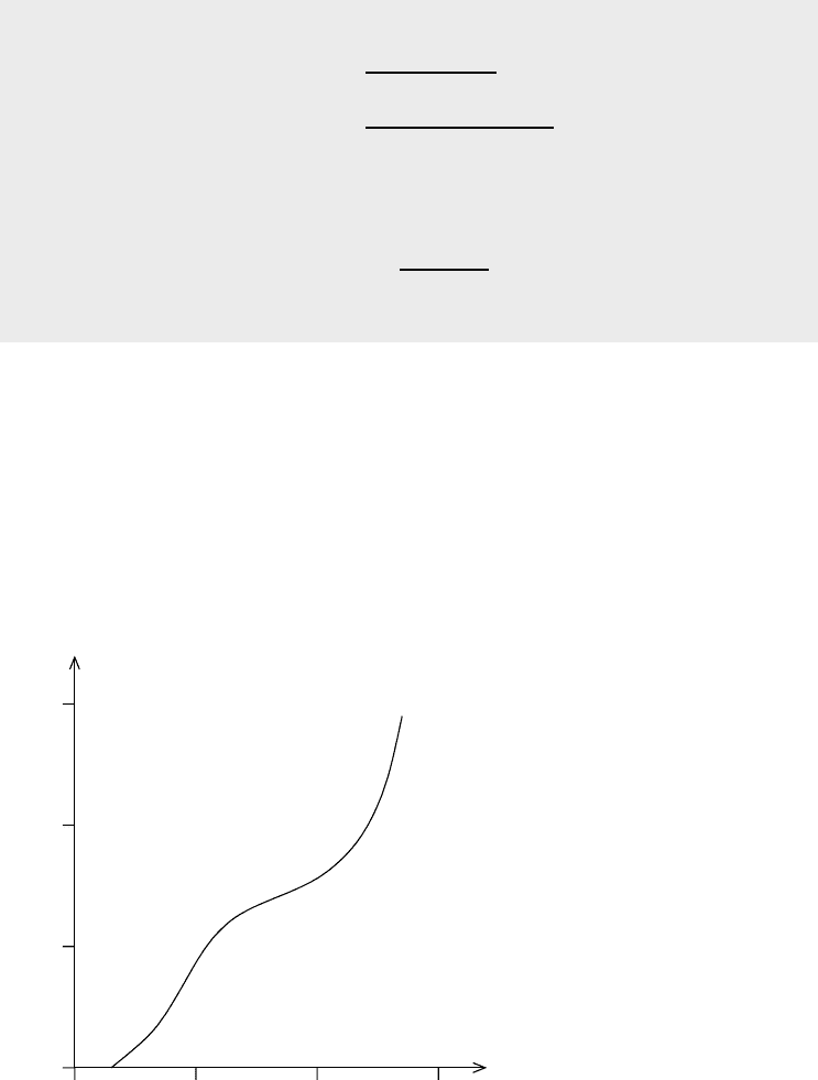
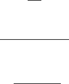
The mean internal gain of an APD is a function of the applied voltage since
the energy gained by the electrons between collisions depends on the electric field
strength. The bias-gain curve of a typical APD is shown in Fig.6.5.25. It is apparent
from this figure that an APD can, in principle, be operated in a range of gains, which
makes it a versatile device that can be tuned according to the level of the incident
light.
10
3
10
2
1
10
200
400
6000
Reverse Bias (V)
G
a
i
n
Figure 6.5.25: Variation of gain
with applied reverse bias in a
typical APD.
In most applications, APDs are used in a region of the voltage-gain curve where
the relationship is approximately linear. In such a region the variation of gain with

410 Chapter 6. Scintillation Detectors and Photodetectors
voltage can be written as
dG
dV
= k
v
G %V
−1
, (6.5.59)
where V is the applied voltage and k
v
is a constant that depends on the APD
material and construction. Generally its value lies between 3 and 4.
Another parameter on which the gain depends heavily is the temperature. The
gain increases with decrease in temperature according to the simple relation
dG
dT
= −k
t
G %
0
C
−1
, (6.5.60)
where T is the temperature in Celcius and k
t
is a constant that depends on the type
of APD. It normally assumes a value between 2 and 3. The negative sign simply
signifies the inverse relationship between the gain and the temperature.
The above equations imply that operating an APD at a fixed temperature and
voltage would yield a fixed gain. What these equations do not imply is that there
is no uncertainty associated with the gain. As a matter of fact, the biggest prob-
lem with APD gain is actually its inherent uncertainty and not its variation with
temperature and voltage. This uncertainty stems from the noisy nature of the car-
rier impact ionization process that multiplies the charges. Any measurement from
an APD is therefore subject to these fluctuations as well, which of course can be-
come undesirable for high precision measurements such as single photon counting.
The fluctuations in the APD gain has thus become an active area of research and
development.
Although some researchers prefer to work directly with the gain but most prefer
the gain fluctuations that are characterized by the so called excess noise factor
defined as
F =
G
2
G
2
, (6.5.61)
where G is the APD gain and represents the mean value. A number of mathemat-
ical models exist that transform the above equation into a numerically computable
form (see, for example (23)). We will not go into that discussion but it is worth men-
tioning here that the excess noise factor and hence fluctuations in the gain depend
on
the mean APD gain,
the ionization coefficients of the charge carriers (electrons and holes), and
the multiplication region.
The variation of the excess noise factor with the mean gain is the most profound
one among the three. Though some APDs behave a bit differently, but generally
there exists linear relationships between these two parameters, that is
F ≈ AG + B, (6.5.62)
where A and B are constants that depend on the APD material and construction.
Typically A has a value on the order of 10
−3
, while B assumes a value of around 2.
6.5. Photodetectors 411
C.3 Quantum Efficiency and Responsivity
The quantum efficiency of a photodiode detector is used to characterize its efficiency
of creating charges that contribute to the output signal. It is generally defined by
the ratio
ξ =
rate of electron generation
intensity of incident photons
. (6.5.63)
Note that here the rate of electron generation refers to the electrons that contribute
to the output signal. Hence, if I
γ
is the current in amperes that generates the output
signal and is generated by the incident photons, then we can write
Rate of electron generation =
I
γ
e
s
−1
, (6.5.64)
with e being the electronic charge. I
γ
is sometimes also referred to as the pho-
tocurrent. Since the photocurrent in an APD actually gets amplified by a factor G,
therefore we can also write the above expression as
Rate of electron generation =
I
out
Ge
s
−1
, (6.5.65)
where I
out
= GI
γ
is the current measured at the APD output and G is the
mean APD gain. The second term in the definition of the quantum efficiency is the
intensity of incident photons. It can be calculated from the incident power P and
the mean wavelength λ of the incident photons through the relation
Intensity of incident photons =
Pλ
hc
s
−1
. (6.5.66)
Hence the expression for the quantum efficiency can be written as
ξ =
I
out
/Ge
Pλ/hc
=
I
out
P G
hc
eλ
=
R
G
hc
eλ
, (6.5.67)
where R = I
out
/P is known as the responsivity of the photodetector. Responsivity
is a standard parameter that is often quoted by the APD manufacturers and is used
to compare the characteristics of different APDs. Its generally quoted units are
amperes per watt. The expression for responsivity in terms of the efficiency can be
deduced from the above expression as
R =
Geξλ
hc
, (6.5.68)
or in Standard units it can be written as
R =8.07 × 10
5
Geξλ AW
−1
. (6.5.69)

412 Chapter 6. Scintillation Detectors and Photodetectors
Example:
An APD having a gain of 20 and responsivity of 8 A/W is subject to a
photon beam of intensity 6.5 × 10
9
s
−1
. Calculate the quantum efficiency of
the APD at 1.6 µm. Also compute the average photocurrent.
Solution:
The efficiency can be calculated from equation 6.5.67.
ξ =
R
G
hc
eλ
=
8
20
6.63 × 10
−34
2.99 × 10
8
(1.602 ×10
−19
)(1.6 × 10
−6
)
=0.31
To compute the average photocurrent I
γ
we use the basic definition of respon-
sivity, that is
R =
I
out
P
.
Using I
out
= GI
γ
this can be transformed into
I
γ
=
P R
G
=
Rφhc
Gλ
where φ = Pλ/hc is the incident photon intensity. Substituting the given
values in the above equation yields
I
γ
=
(8)
6.5 × 10
9
6.63 × 10
−34
2.99 × 10
8
(20) (1.6 × 10
−6
)
=3.2 × 10
−10
A
=0.32 nA.
C.4 Modes of Operation
Just like PMTs, APDs can also be operated in analog or digital modes. However
for APDs they are generally referred to as linear and Geiger modes.
We saw in the chapter on gas filled detectors that operating a detector in Geiger
region means applying a bias voltage high enough to cause breakdown in the gas.
This is also true for APDs operating in the Geiger mode. If a high enough reverse bias
is applied to the APD, it will cause a large current pulse whenever a photon produces
charge pairs in the bulk of the material. Hence in this way the detector can be used
as a photon counting device just like a PMT. The problem, however, is the dark
current in the bulk of the material, which is significant even at room temperatures.
The trick, therefore, is to operate the detector at very low temperatures. Silicon
APDs have been found to have very low leakage or dark currents and therefore high
6.5. Photodetectors 413
photon counting capabilities. With a pulse resolution of as low as 20ps, a gain of
as high as 10
8
, and a quantum efficiency approaching 80%, the APDs are becoming
more and more popular in single photon counting applications.
C.5 Noise Considerations
APDs are generally operated at low light levels due to their signal amplification
characteristics. Their sensitivity is therefore limited by their inherent noise. There
are different sources of noise in an APD, the most important of which are listed
below.
Leakage Current: An APD can have two types of leakage currents: surface
leakage current and bulk leakage current. The bulk leakage current, which flows
in the bulk of the material, is affected by the high electric field in a manner
similar to the signal current, and hence gets amplified. We will represent the
gain associated with the bulk leakage current by G
l
to differentiate it from
the multiplication factor for the signal. If I
ls
and I
lb
are the surface and bulk
leakage currents respectively then the total leakage current I
l
in an APD having
a mean gain G can be expressed as
I
l
= I
ls
+ G
l
I
lb
. (6.5.70)
The contribution of surface leakage current to the total leakage current is quite
small and can therefore be safely ignored for most computations. Hence we
can write
I
l
≈G
l
I
lb
. (6.5.71)
The fluctuations of this leakage or dark current is given by the shot noise
formula
σ
2
l
=2eI
l
BG
l
2
F
l
, (6.5.72)
where e is the unit electrical charge, B is the bandwidth of the system, and F
l
is the excess noise factor for the leakage current. Note that here we have made
use of the definition of the excess noise factor given earlier, that is
F
l
=
G
2
l
G
l
2
. (6.5.73)
The excess noise factor in terms of electron ionization rate α,depletionwidth
d, ionization rate ratio u, and gain factor G
l
is given by (see, for example (21))
F
l
=
(1 + αdG
l
)(1+uαdG
l
)
G
l
. (6.5.74)
Determination of the noise factor and the fluctuations of the dark current
requires the knowledge of the multiplication factor or gain, which can be com-
puted from the relation (21)
G
l
=
1 − e
−αd(1−u)
αd
e
−αd(1−u)
− u
. (6.5.75)

414 Chapter 6. Scintillation Detectors and Photodetectors
It is instructive to compare equations 6.5.57 and 6.5.74, which represent the
gains of signal and dark currents respectively. It can be shown that they are
related through the relation
G
l
=
1
αd
[G
e
−1] . (6.5.76)
Excess Noise: We have already introduced the term excess noise factor to
characterize the fluctuations in the APD gain. This factor actually repre-
sents the so called excess noise that is related to the statistical nature of the
underlying particle interactions that take place during the process of charge
multiplication. Due to these fluctuations the distribution of amplitudes of the
output current pulses assume a finite width even if the incident light can be
described by an impulse or delta function.
We have already introduced the expression for the excess noise factor for the
dark current (see equation 6.5.74. For the signal current due to electrons the
noise factor can be written as (41)
F
e
= uG
e
+
2 −
1
G
e
(1 − u)
, (6.5.77)
where, as before, u represents the hole to electron ionization rate ratio and
G
e
is the mean signal gain.
Thermal Noise: Thermal noise, though important, is not actually related to
the APD itself. It refers to the noise generated in the output circuitry due
to thermal agitations of the current carriers. During the discussion on PMT
noise, we introduced the term Johnson noise to characterize the thermal noise
generated in the preamplifier. The same argument can be applied for the case
of APDs as well. Hence the variance of output current due to thermal noise is
given by
σ
t
=
4F
t
k
B
TB
R
eqv
, (6.5.78)
where F
t
is the noise figure for the noise source (the output circuitry), k
B
is the
familiar Boltzmann’s constant, T is the absolute temperature, B is the system
bandwidth, and R
eqv
is the equivalent impedance of the output circuit.
The signal-to-noise ratio can be determined by noting that the noise sources
described above are independent of each other, since this allows us to represent the
total fluctuations or variance of the output current by
σ
2
out
= σ
2
c
+ σ
2
l
+ σ
2
t
, (6.5.79)
where the subscripts out, c, l,andt refer to the variances corresponding to the
output signal, charge carriers, leakage current, and thermal noise respectively. If
the output signal is due to the electrons, as is usually the case, then the fluctuations
in the electron current can be written as
σ
2
c
=2eI
e
BG
e
2
F
e
, (6.5.80)
6.5. Photodetectors 415
where B is the bandwidth of the system, G
e
is the mean electron multiplication
factor, I
e
is the mean electron current, and F
e
is the excess noise factor for the elec-
tron current. To compute the signal-to-noise ratio we also need the signal current,
which for this case is simply given by I
e
G
e
since I
e
is the signal current before
multiplication. The expression for the signal-to-noise ratio can now be written as
S/N =
I
e
G
e
σ
out
=
I
e
G
e
σ
2
c
+ σ
2
l
+ σ
2
t
=
I
e
G
e
2eI
e
BG
e
2
F
e
+2eI
l
BG
l
2
F
l
+4F
t
k
B
TBR
−1
eqv
. (6.5.81)
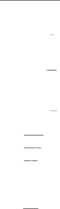
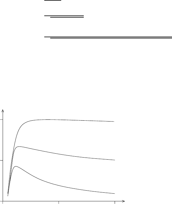
The signal-to-noise ration depends on the mean gain which in turn has a depen-
dence on the ratio of hole and electron ionization rates u.InfactS/N is highly
sensitive to the value of u as can be deduced from Fig.6.5.26. This implicit de-
pendence on u puts a tough constraint on the value of gain that would yield high
signal-to-noise ratio. This is specially true for higher values of u. For small u,the
curve is more or less flat after a certain gain and therefore gives some flexibility in
terms of choosing the gain according to the particular application.
10
−3
u =
10
−2
u =
10
−1
u =
S/N
(
re
l
at
i
ve
)
0
0
0.5
1.0
100
200
M
ea
n
Ga
in
Figure 6.5.26: Dependence
of signal-to-noise ratio of an
APD on the mean gain at
different values of the ratio
of the hole ionization rate to
the electrion ionization rate.
C.6 Radiation Damage
The radiation damage to semiconductor detectors has already been discussed in
the previous Chapter. The damage mechanisms in the APDs are the same as in
conventional semiconductor detectors. The overall effect of the damage is, however,
more dramatic due to the higher sensitivity of these detectors. In an APD being
operated in a hostile radiation environment, the following two distinct types of
radiation induced damages can occur.