Ahsan A. (ed.) Evaporation, Condensation and Heat transfer
Подождите немного. Документ загружается.

Numerical Modeling of Cross-Flow Tube Heat Exchangers with Complex Flow Arrangements
269
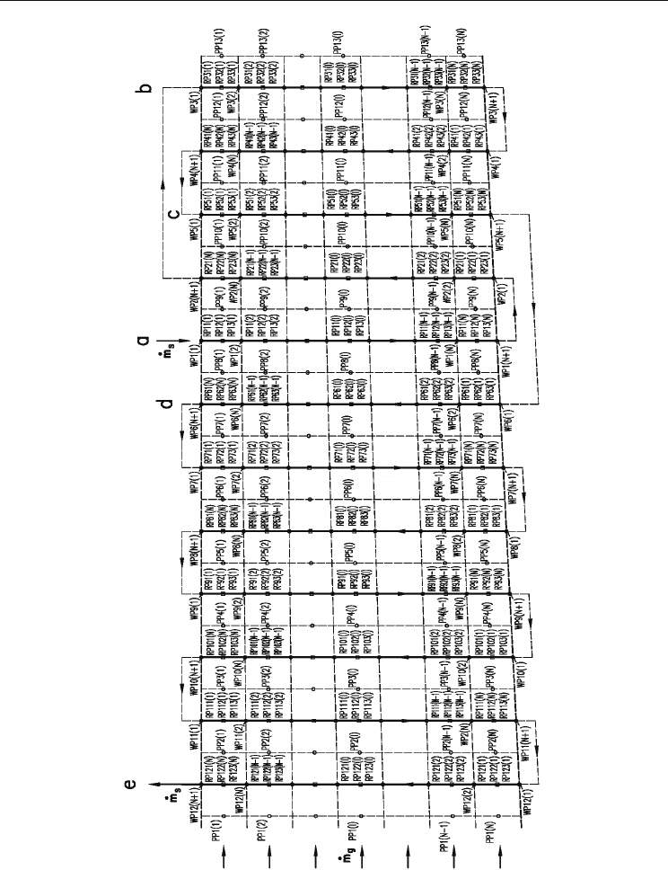
Fig. 4. Superheater flow arrangement and division of superheater into control volumes;
o - flue gas, • - water steam, - tube wall; PP1(1),…,PP1(N) – flue gas temperature at the
nodes before the superheater, WP1(1),…,WP1(N+1) – steam temperature at the nodes in the
first superheater pass.
Evaporation, Condensation and Heat Transfer
270
and dividing Eq. (26) by
,spsi
mc
, we have:
,1 1 , 1 1,
,,
22
1
,
2
11
1,1,...,
1
2
1
2
si si w i
si si
si
TNTNTiN
N
+
++
+
⎡⎤
⎛⎞
⎢⎥
⎜⎟
=−Δ+Δ=
⎜⎟
⎢⎥
+Δ
⎝⎠
⎣⎦
(27)
where:
/
x
xL NΔ=
- the mesh size, L
x
– the tube length.
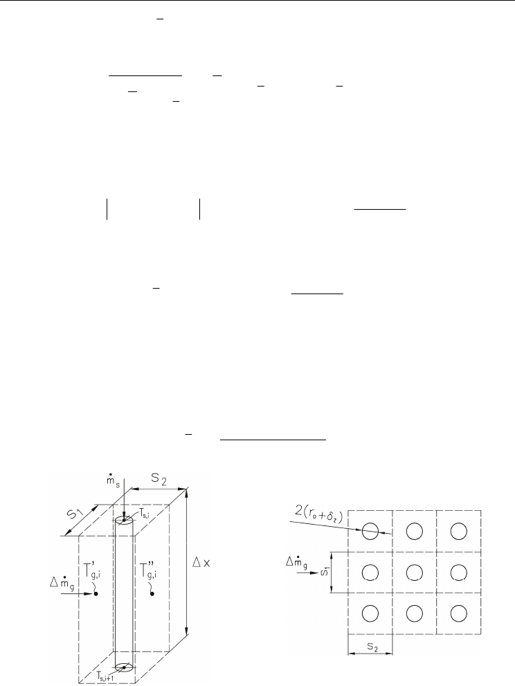
The energy conservation principle for the flue gas applied for the finite control volume
(Fig. 5) is:
()
'"
,,
'"
,,
'"
,, 3,
00
22
2
gi gi
TT
gi gi
gpg g
i
gpg g
ioz
g
wi
TT
mc T mc T r xh T
πδ
⎛⎞
+
⎜⎟
Δ=Δ++Δ −
⎜⎟
⎝⎠
(28)
After rearranging Eq. (28), we obtain:
()
'"
,,
'"
,, , 3,
2
gi gi
gpg
i
g
i
g
iz
g
wi
TT
mc T T Ah T
⎛⎞
+
⎜⎟
Δ−=Δ −
⎜⎟
⎝⎠
(29)
where the mesh outer surface of deposits is (Fig. 6):
()
22
zoz
Ar x
πδ
Δ= + Δ. (30)
The flue gas average specific heat at constant pressure is given by:
() ()
"'
,,
,
2
pg g
i
pg g
i
pg i
cT cT
c
+
=
. (31)
a)
b)
Fig. 5. Finite volume for energy balance on the steam and gas sides (a) and in-line array of
superheater tubes (b).
Numerical Modeling of Cross-Flow Tube Heat Exchangers with Complex Flow Arrangements
271
Equation (29) can be written as:
"'
,,,3,
,
11
1
2
2
g
i
gpg
i
g
z
g
i
g
zw i
gpgi g z
TmchAThAT
mc h A
⎡
⎤
⎛⎞
=Δ−Δ+Δ
⎢
⎥
⎜⎟
⎝⎠
⎣
⎦
Δ+Δ
. (32)
Introducing the mesh number of transfer units for the gas:
() ()
1
'"
,
,
2
,,
2
gz gz
gi
gpgi
gpggi pggi
hA hA
N
mc
mc T c T
+
ΔΔ
Δ= =
Δ
⎡
⎤
Δ+
⎢
⎥
⎣
⎦
(33)
and dividing Eq. (33) by
,
g
pg i
mc
we obtain:
"'
,1,13,
,,
22
1
,
2
11
1 , 1, ... , .
1
2
1
2
gi gi w i
gi gi
gi
TNTNTiN
N
++
+
⎡⎤
⎛⎞
⎢⎥
⎜⎟
=−Δ+Δ=
⎜⎟
⎢⎥
+Δ
⎝⎠
⎣⎦
(34)
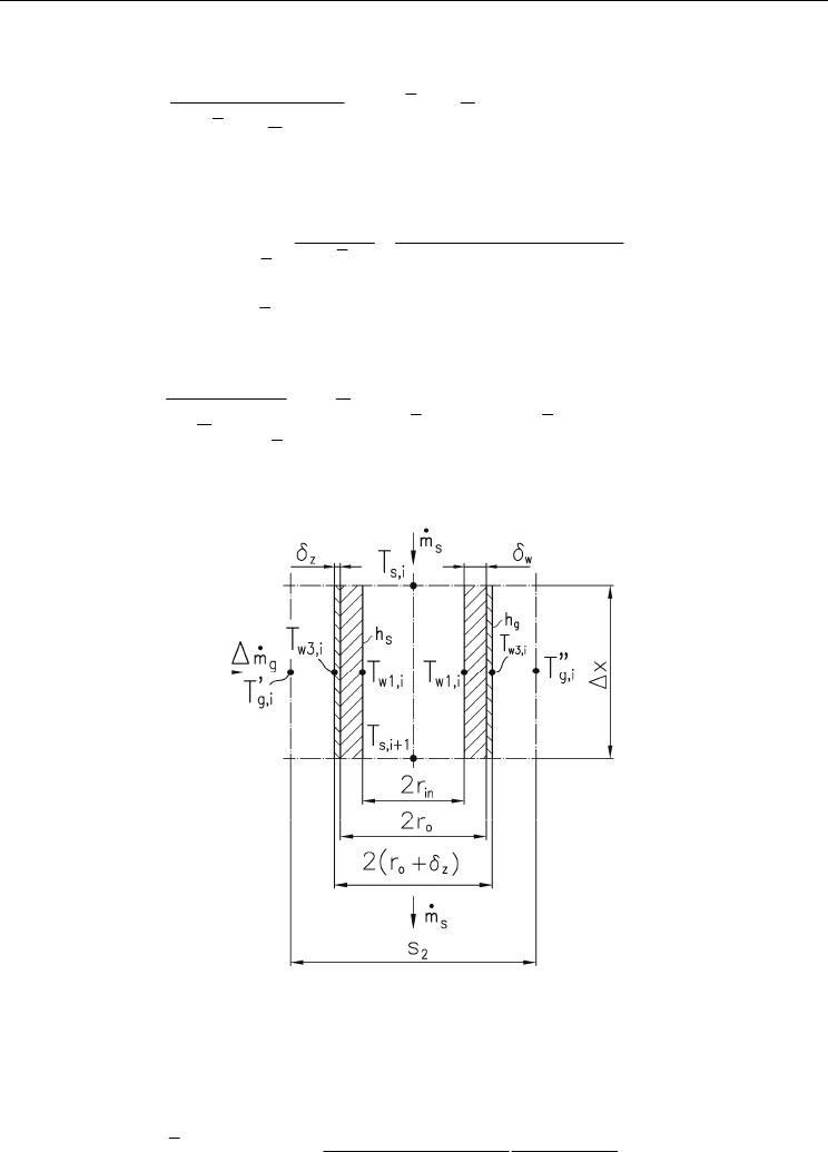
Subsequently, energy conservation equations for the tube wall (Fig. 6) will be written.
Fig. 6. Tube wall with a layer of deposits at the outer tube surfaces.
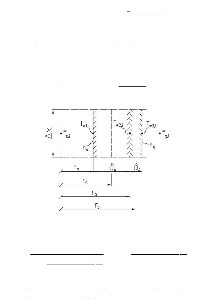
The tube wall and the deposit layer are divided into three finite volumes (Fig. 7).
Energy conservation equations may be written as:
node 1
()
()()
1, 2,
2, 1,
,1,
0
2
wwi wwi
wi wi
ssi wi in c
w
kT kT
TT
hT T d d
ππ
δ
+
−
−+ =, (35)
Evaporation, Condensation and Heat Transfer
272
where:
()
,,1
,
/2 ,
2
si si
cino inosi
TT
ddd rrT
+
+
=+ =+ =
.
node 2
()()
1, 2,
1, 2, 3, 2,
0
2
wwi wwi
wi wi wi wi
cz s
wz
kT kT
TT TT
dk d
ππ
δδ
+
−−
+=, (36)
where:
2
soz oz
dd r
δδ
=+= +
.
node 3
()
()
2, 3,
,3,
20
wi wi
ggi wi o z z s
z
TT
hT T d k d
πδ π
δ
−
−++ =
. (37)
Fig. 7. Division of the tube wall and deposit layer into three control volumes.
Algebraic equations (35) – (37) can be rewritten in a form which is suitable for solving
equation sets by using the Gauss – Seidel method:
()()
()()
1, 2,
1, , 2
1, 2,
1
2
2
wwi wwi
c
wi ssiin w
w
wwi wwi
c
sin
w
kT kT
d
ThTdT
kT kT
d
hd
δ
δ
⎡
⎤
+
⎢
⎥
=+
⎢
⎥
+
⎣
⎦
+
, (38)
()()
()()
1, 2,
2, 1, 3,
1, 2,
1
2
2
wwi wwi
cs
wi wi z wi
wz
wwi wwi
cz
s
wz
kT kT
dd
TTkT
kT kT
dk
d
δδ
δδ
⎡
⎤
+
⎢
⎥
=+
⎢
⎥
+
⎣
⎦
+
, (39)

Numerical Modeling of Cross-Flow Tube Heat Exchangers with Complex Flow Arrangements
273
()
()
3, , 2,
1
2
2
s
wi
g
oz
g
iz wi
z
s
go z z
z
d
ThdTkT
d
hd k
δ
δ
δ
δ
⎡
⎤
=++
⎢
⎥
⎡⎤
⎣
⎦
++
⎢⎥
⎣⎦
. (40)
Equations (38) – (40) can be used for building mathematical models of steam superheaters.
To solve Eqs. (27), (34) and (38) – (40) two boundary conditions are prescribed: inlet steam
temperature
,sinlet
T and flue gas temperature
,
g
inlet
T before the superheater:
,
1(1)
sinlet
WP T= and
,
1( ) , 1,...,
ginlet
PP I T I N== (41)
5. Convection and radiation heat transfer coefficients
The convective heat transfer coefficient at the tube inner surface
s
h and the heat transfer on
the flue gas side
cg
h were calculated using correlations given in (Kuznetsov et al., 1973). The
effect of radiation on the heat transfer coefficient
g
h is accounted for by adding the
radiation heat transfer coefficient
rg
h (Taler et al., 2009c; Kuznetsov et al., 1973) to the
convective heat transfer, e.g.
g
cg rg
hh h=+.
For in-line arrays, in which tubes in successive rows are in-line in the direction of flue gas
flow, the following correlation was used for calculating convective heat transfer coefficient
cg
h
(Kuznetsov et al., 1973):
0.65 0.33
0.2 Re Pr
cg s z g g
Nu C C= . (42)
Similar correlation was used for staggered tube arrays:
0.6 0.33
Re Pr
cg s z g g
Nu C C= (43)
where:
()
2/
c
g
c
g
oz
g
Nu h d k
δ
=+
- Nusselt number, Re - Reynolds number, Pr - Prandtl
number,
,
sz
CC - correction factors for tube arrangement and for the effect of number of tube
rows in the array, respectively.
The cross flow Reynolds number is given by:
()
max
Re /
gg
oz
g
wd
ρ
δ
μ
=+
, where
g
ρ
-
density,
g
μ
- dynamic viscosity,
maxg
w - maximum gas velocity, calculated for the minimum
flow area between tubes normal to the local flow direction.
For calculating the heat transfer coefficient on the steam side the well known Dittus –
Boelter equation was used:
0.8 0.33
0.023Re Pr
ssst
Nu C= (44)
where:
t
C - correction factor for surface-to-bulk physical property variations.
The radiation heat transfer coefficients were also calculated using simple formulas, which
are widely applied to the design of boilers and other heating equipment. The Standard
Method (Kuznetsov et al., 1973; Kakaç, 1991) applies the following formula:
44
1
2
g
w
w
rg g
g
w
TT
h
TT
ε
σε
−
+
=
−
(45)
Evaporation, Condensation and Heat Transfer
274
where:
8
5.67 10
σ
−
=× W/(m
2
⋅ K
4
) – Stefan-Boltzmann constant, ε
g
, ε
w
–gas and tube wall
emissivity, respectively,
g
T - gas mean temperature over tube row,
w
T - tube wall
temperature.
When solid particles are absent in the gaseous combustion products (gas or oil fired boilers),
then the following modified formula (Kuznetsov et al., 1973) is recommended:
()
3.6
44
/
1
2
g
w
gg
w
rg g
gw
TTTT
h
TT
ε
σε
−
+
=
−
. (46)
The radiation heat transfer coefficient
rg
h can be calculated using a simple formula derived
in (Taler et al., 2009c):
()
()
44
g
w
e
rg
e
g
w
TT
as
h
as
TT
σε
ε
−
=
+
−
(47)
where: a – absorption coefficient, s – geometric mean beam length,
2/(2 )
ew w
εε ε
=−.
The mean beam length s for in-line and staggered tube arrays is given by:
12
2
(2)
4
1
4
(2)
oz
oz
ss
d
sC
d
δ
π
δ
⎛⎞
+
=−
⎜⎟
⎜⎟
+
⎝⎠
(48)
where C < 4.0. A value of C = 3.6 works well in many situations (Hewitt et al., 1994;
Rayaprolu, 2009; Taler et al., 2009c). The coefficient C is assumed to be between C = 3.4
(Stultz et al., 1992) and C = 3.8 (Brandt, 1985). In cases of lager values of the product as, the
value of the coefficient C is lower (3.4 ≤ C ≤ 3.6).
6. Example of superheater modeling
The calculations are based on the following data: tube’s outside diameter, 0.042 ,
o
dm= tube’s
inside diameter,
0.032
in
dm= , inlet flue gas temperature,
,
632.6 º
ginlet
TC=
, inlet steam
temperature,
,
337.7 º
sinlet
TC= , steam mass flow rate 46.2 /
s
mkgs=
, mean flue gas velocity
in the narrowest cross section, 7.19 /
g
wms= , ash deposition thickness 0.002
z
m
δ
= , and
thermal conductivity of ash layer
0.07 /( )
z
kWmK=
.
The thermal conductivity of the tube material is given by the following expression:
52
35.54 0.004084 2.0891 10
w
kTT
−
=+ − ⋅ , (49)
where the thermal conductivity
k
w
is in W/(m⋅K) and temperature T in ºC.
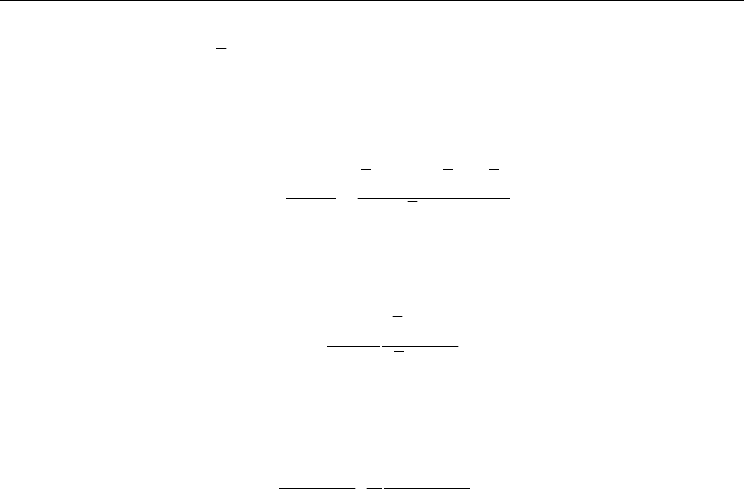
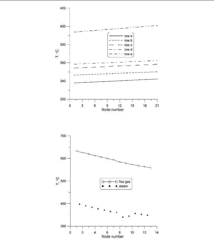
Figures 8 and 9 illustrate the predictions of the mathematical model. The calculated steam
temperature and mean flue gas temperature behind the superheater are: 400.9 ºC and
558.6 ºC, respectively. The computed steam temperature increase is:
s
TΔ=
400.9-337.7=63.2
K while the measured increase is:
63.3
s
TKΔ= .
The agreement between the measured and calculated steam temperature rise is very good.
Numerical Modeling of Cross-Flow Tube Heat Exchangers with Complex Flow Arrangements
275
Fig. 8. Steam temperature distribution in selected passes; a, b, c, d, e – symbol of the pass
(Fig. 4).
Fig. 9. Flue gas and steam temperature in the middle of superheater in direction of flue gas
flow (from the left to the right side of superheater).
The mathematical model of the superheater developed in the paper allows to determine
the wall and ash deposits temperature. The tube temperature at the inner and outer surfaces
at the inlet of the superheater are
1,1
341.0 º
w
TC= and
2,1
341.89 º
w
TC= .
The temperature rises significantly over the ash deposit layer since the temperature at the
outer surface of the deposit layer is
3,1
522.28 º
w
TC= . Similar results are obtained at the outlet
of the superheater:
1, 1
403.61 º
wN
TC
+
= ,
2, 1
404.45 º
wN
TC
+
= , and
3, 1
573.63 º
wN
TC
+
=
(Fig. 7).

Evaporation, Condensation and Heat Transfer
276
It can be seen from the inspection of the results that the ash layer has a great influence on
the temperature of ash deposit layer. With an increasing ash deposit layer the heat flow rate
from the flue gas to the steam decreases since the temperature difference between the flue
gas and ash deposit surface drops.
7. Conclusions
Cross-flow tube heat exchangers find many applications in practice. An example of such an
exchanger is a steam superheater, where the steam flows inside the tubes while heating flue
gas flows across the tube bundles. The mathematical derivation of an expression for the
mean temperature difference becomes quite complex for multi-pass cross-flow heat
exchangers with many tube rows and complex flow arrangement. When calculating the heat
transfer rate, the usual procedure is to modify the simple counter-flow LMTD (Logarithmic
Mean Temperature Difference) method by a correction
F
T
determined for a particular
arrangement. The heat flow rate
Q
transferred from the hot to cool fluid is the product of
the overall heat transfer coefficient
U
A
, heat transfer area A, correction factor F
T
and
logarithmic mean temperature difference
ΔT
lm
. The heat transfer equation then takes the
form:
ATlm
QUAF T=Δ
. However, to calculate the steam, flue gas and wall temperature
distributions, a numerical model of the superheater is indispensable. Superheaters are the
tube bundles that attain the highest temperatures in a boiler and consequently require the
greatest care in the design and operation. The complex superheater tube arrangements
permit the economic trade-off between material unit costs and surface area required to
obtain the prescribed steam outlet temperature. Very often, various alloy steels are used for
each pass in modern boilers. High temperature heat exchangers, like steam superheaters, are
difficult to model since the tubes receive energy from the flue gas by two heat transfer
modes: convection and radiation. The division of superheaters into two types: convection
and radiant superheaters is based on the mode of heat transfer that is predominant. In
convection superheaters, the portion of heat transfer by radiation from the flue gas is small.
A radiant superheater absorbs heat primarily by thermal radiation from the flue gas with
little convective heat flow rate. The share of convection in the total heat exchange of platen
superheaters located directly over the combustion chamber amounts only to 10 to 15%.
In convective superheaters, the share of radiation heat exchange is lower, but cannot be
neglected. Correct determination of the heat flux absorbed through the boiler heating
surfaces is very difficult. This results, on the one hand, from the complexity of heat transfer
by radiation of flue gas with a high content of solid ash particles, and on the other hand,
from the fouling of heating surfaces by slag and ash. The degree of the slag and ash
deposition is hard to assess, both at the design stage and during the boiler operation. In
consequence, the proper size of superheaters can be adjusted after taking the boiler into
operation. In cases when the temperature of superheated steam at the exit from the
superheater stage under examination is higher than design value, then the area of the
surface of this stage has to be decreased. However, if the exit temperature of the steam is
below the desired value, then the surface area is increased.
To overcome the difficulties mentioned above, the general principles of mathematical
modeling of steady-state and unsteady heat transfer in cross-flow tube heat exchangers with
complex flow arrangements which allow of the simulation of multipass heat exchangers
with many tube rows were presented. The finite volume method (FVM) was used to derive
the algebraic equation system for determining flue gas, wall, and steam temperature at the

Numerical Modeling of Cross-Flow Tube Heat Exchangers with Complex Flow Arrangements
277
nodes of the finite volumes. A numerical model of multipass steam superheater with twelve
passes was developed. The convection and radiation heat transfer was accounted for on the
flue gas side. In addition, the deposit layer was assumed to cover the outer surface of the
tubes. The calculation results were compared with the experimental data. The computed
steam temperature increase over the entire superheater corresponds very well with the
measured steam temperature rise. The developed modeling technique can especially be
used for modeling tube heat exchangers when detail information on the tube wall
temperature distribution is needed.
8. Symbols
a
- absorption coefficient, 1/m
A
- area, m
2
in
A
,
o
A
- inside and outside cross section area of the tube, m
2
c
- specific heat, J/(kg
⋅K)
c
- mean specific heat, J/(kg
⋅K)
p
c
- specific heat at constant pressure, J/(kg
⋅K)
F
T
- correction factor for a particular flow arrangement,
h
- heat transfer coefficient, W/(m
2
⋅K)
k
- thermal conductivity, W/(m
⋅K)
x
L
- tube length in the heat exchanger, m
Nu - Nusselt number
m
- mass, kg
m
- mass flow rate, kg/s
Pr - Prandtl number
Q
- heat flow rate, W
r
- radius, m
Re - Reynolds number
s
1
- pitch of tubes in plane perpendicular to flow (height of fin), m
s
2
- pitch of tubes in direction of flow, m
t
- time, s
T
- temperature, °C
'
2
T ,
''
2
T
- gas temperature before and after tube row, °C
U
- perimeter, m
U
A
- overall heat transfer coefficient, W/(m
2
⋅K)
in
U ,
o
U
- inner and outer perimeter of the oval tube, respectively, m
w
- fluid velocity, m/s
x, y, z
- Cartesian coordinates
/
x
xxL
+
=
- dimensionless coordinate
2
/yys
+
=
- dimensionless coordinate
8.1 Greek symbols
/( )kc
α
ρ
=
- thermal diffusivity, m
2
/s
g
mΔ
- flue gas mass flow rate through the control volume , kg/s,

Evaporation, Condensation and Heat Transfer
278
TΔ
- temperature difference, K
xΔ
,
yΔ
- control volume size in x and
y
direction, m
1/xN
+
Δ=
- dimensionless control volume size
δ
- thickness, m,
ε
- emissivity,
ρ
- density, kg/m
3
τ
- time constant, s
8.2 Subscripts
g - flue gas
lm - logarithmic mean
m - mean
r - tube
s - steam
w - wall
in - inner
o - outer
1 - fluid flowing inside the tube
2 - fluid flowing in perpendicular direction to tubes
9. References
Brandt, F. (1985). Wärmeübertragung in Dampferzeugern und Wärmetauschern, FDBR-
Fachverband Dampfkessel-Behälter- und Rohrleitungsbau, ISBN 3-8027-2535-2
Vulkan-Verlag, Essen
Hewitt G. F., Shires G. L., Bott T.R. (1994).
Process heat transfer, CRC Press, ISBN
0-8493-9918-1, Boca Raton
Kakaç, S., Boilers (1991).
Evaporators, and Condensers, Wiley, ISBN 0471621706, New York,
Kröger D. G. (2004).
Air-cooled Heat Exchangers and Cooling Towers, ISBN 0820603007,
Chemical Publishing Company, New York, USA
Kuznetsov N. V., Mitor V.V., Dubovskij I.E., Karasina E.S., Editors (1973).
Standard Methods
of Thermal Design for Power Boilers
, Central Boiler and Turbine Institute, Energija,
UDK 621 181 001 24 : 536 7 (083 75), Moscow, (in Russian)
Rayaprolu K.(2009).
Boilers for Power and Process, CRC Press, ISBN 978-14200-7536-6,
Boca Raton
Stultz S.C., Kitto J.B., Editors (1992).
Steam. Its Generation and Use., The Babcock &
Wilcox Company, Fortieth edition, ISBN 09634570-0-4, Barberton, Ohio
Taler D. (2009a).
Dynamics of Tube Heat Exchangers, University of Science Publishing
Hous (UNWD AGH), ISSN 0867-6631, Cracow (in Polish)
Taler J., Trojan M., Taler D. (2009b).
Archives of Thermodynamcs, Vol. 30, No. 2,
59 – 76, ISSN 1231 - 0956
Taler J., Taler D. (2009c).
Heat Transfer Engineering, 30, 661-669, ISSN 0145-7632