ASM Metals HandBook Vol. 14 - Forming and Forging
Подождите немного. Документ загружается.

ALPID Results: Field Variables and Flow Lines. The available results of finite-element analysis include the
following field variables:
• Stress distribution
• Strain distribution
• Strain rate distribution
• Velocity distribution
• Displacement as represented by FEM mesh distortion
These results are normally too tedious to evaluate as printed numbers; graphical representation by way of contour plots,
velocity vector plots, and mesh distortion plots are usually used. The resolution (accuracy) with which the field variables
are computed are a direct function of the FEM mesh density. In addition to the above field variables, the load requirement
as a function of stroke is also computed, and a graphical dis la of results is available.
The mesh distortion results from ALPID can be used to obtain some estimate of the expected orientation of flow lines
(Fig. 11), but are not always adequate for two reasons. First, the grid distortion plots represent the FEM mesh distortion,
not the actual flow lines. The original FEM mesh may have arbitrary topology, and this can result in distortion plots that
have no relationship to flow lines. This technique is adequate only when the initial FEM mesh is uniform and suitably
oriented. Second, even when the original FEM mesh has suitable orientation and topology to represent flow lines, if
remeshing is performed in the course of simulation, all flow line orientation developed prior to remeshing is lost.
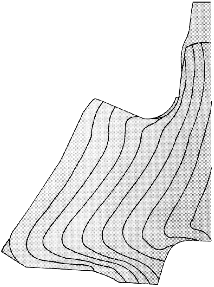
Fig. 11 Typical flow lines in a forging
An ALPID postprocessing feature has recently been added for representing flow lines typically observed in worked
metals (Ref 59). It is especially significant that the ability to develop the simulated flow lines can bridge remeshing
operations. The addition of this feature offers two options to account for the cases typically encountered, as follows.
No Preexisting Flow Lines in Billet. When the ALPID simulation is for a primary working operation, no prior flow
lines exist. The technique offered here is to place circles on the simulation cross section and then provide the ability to
follow the distortion of these circles into flow lines. An example of this technique is given in Fig. 12(a).
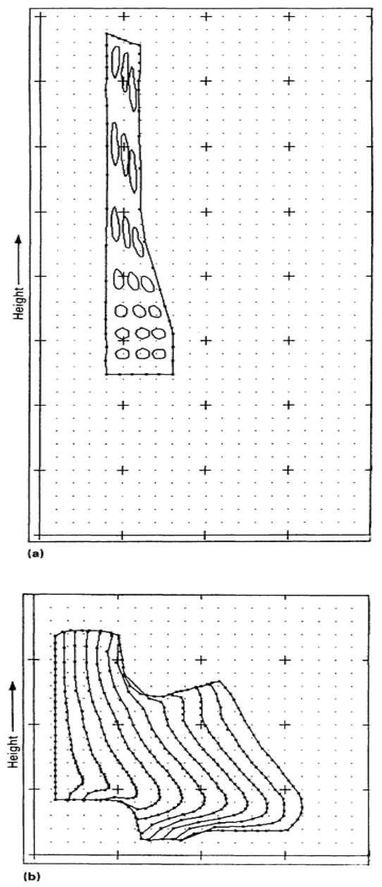
Fig. 12
ALPID simulations of metal flow after forming. (a) Flow lines in extrusion of a cast billet; distance
between consecutive dots is 3.18 mm (0.125 in.). (b
) Flow lines in a disk forging; distance between consecutive
dots is 19.7 mm (0.775 in.).

Preexisting Flow Lines in Billet. When the ALPID simulation is for an operation using an already worked billet or a
forged preform, prior flow lines exist. In this case, the technique offered is to provide flow lines as input to the simulation
and then to follow these flow lines through the course of the simulation. An example of this technique is given in Fig.
12(b).
References cited in this section
6. S.M. Doraivelu et al., Int. J. Mech. Sci., Vol 26, 1984, p 527
53.
S.I. Oh, Finite Element Analysis of Metal Forming Problems With Arbitrarily Shaped Dies,
Int. J. Mech.
Sci., Vol 17, 1982, p 293
54.
O.C. Zienkiewicz, The Finite Element Method, 3rd ed., McGraw-Hill, 1977
55.
W.T. Wu and S.I. Oh, ALPIDT: A General Purpose FEM Code for Simulation of Non-
Isothermal Forming
Processes, NAMRC-XIII, University of California, Berkeley, 1985
56.
Y.T. Im, Ph.D. dissertation, University of California, Berkeley, 1985
57.
J.J. Park and S. Kobayashi, Three-Dimensional Finite Element Analysis of Block Compression,
Int. J.
Mech. Sci., Vol 26, 1984, p 165-176
58.
J.C. Malas, "A Thermodynamic and Continuum Approach to the Design and Control of Precision Forging
Processes," Wright State University, 1985
59.
H. Nitin, M.S. thesis, Ohio University, 1987
Modeling Techniques Used in Forging Process Design
H. L. Gegel and J.C. Malas, Air Force Wright Aeronautical Laboratories/Materials Laboratory; S.M. Doraivelu and V.A. Shende,
Universal Energy Systems, Knowledge Integration Center
Example Applications of ALPID
Spike Forging. In spike forging, a cylindrical billet is forged in an impression die containing a central cavity (Ref 60).
The deformation characteristics of spike forging are such that the portion of the material near the outside diameter flows
radially, while the portion near the center of the top of the surface is extruded, forming a spike.
In this application, the primary objective was to determine the conditions that would allow complete die filling in spike
forging. For this purpose, the constitutive equations for the + Ti-6Al-2Sn-4Zr-2Mo microstructure at 954 °C (1750
°F), which exhibits strain rate hardening, were selected for the analysis. The die shape and the specimen with the selected
mesh pattern are illustrated in Fig. 13.
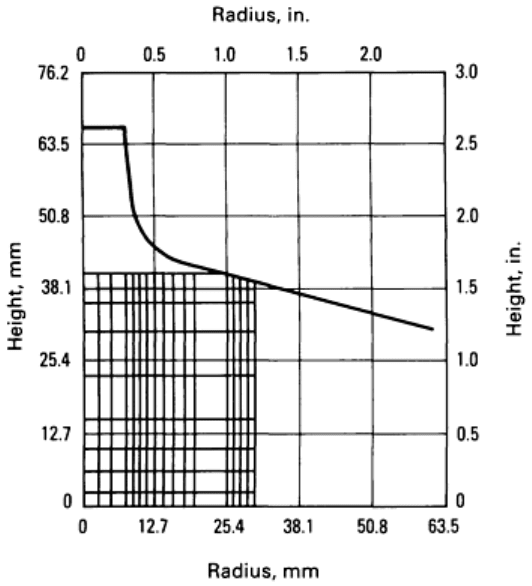
Fig. 13 Die shape and specimen showing mesh pattern selected for ALPID simulation of spike forging.
See also
Fig. 14.
Simulations were performed for frictional conditions of friction parameter m' = 0 to 0.8 in steps of 0.2. However, the
results are presented for only two frictional conditions, namely, m' = 0.2 and 0.6. Figures 14(a) and 14(b) show the flow
pattern obtained for various steps in the operation at these two frictional conditions. Complete die filling was obtained
without remeshing when a frictional condition of m' = 0.6 was used. The total average deformation undergone by the
billet during die filling was 67%. The lateral flow and the radial flow were found to be sensitive to frictional conditions--
the higher the friction, the higher the spike height for the amount of ram displacement.
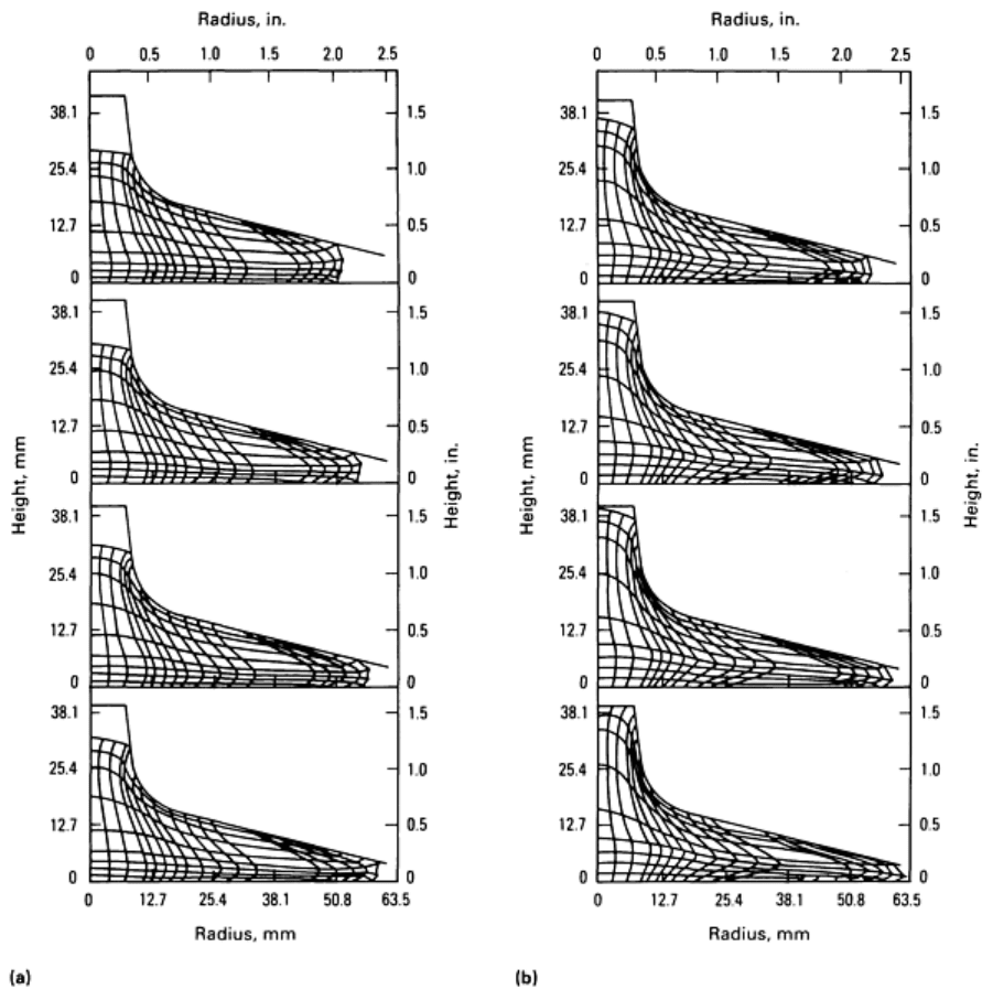
Fig. 14 Simulations of flow patterns during spike forging at reductions of (top to bottom) 64, 65,
66, and 67%
and two different friction conditions. (a) Friction parameter, m' = 0.2. (b) m' = 0.6
The simulation of a rib-web forging of titanium alloy is shown in Fig. 15 and was made to investigate the
possibility of defect generation due to improper die design (Ref 61). These isothermal predictions substantiated the
intuition and experience of titanium forging designers. The defect that would have formed in the actual forging was a lap.
Other simulations for the nonisothermal forging of the same titanium alloy showed that temperature gradients worsened
the problem, indicating that this die design was very poor.
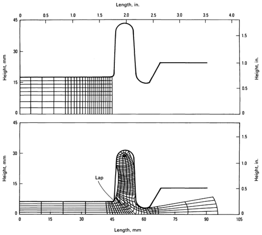
Fig. 15 ALPID simulation of metal flow during the forging of a rib-
web titanium part. In this case, ALPID
correctly predicted formation of a forging defect (lap).
For a truck-gear forging, the nature of the grid distortion in the final die position is shown in Fig. 16 (Ref 61, 62).
The significance of this simulation is that various flash geometries can be simulated for optimizing material flow and
obtaining complete filling. This is an axisymmetric forging of a steel alloy; it should be noted that the flash at the part
centerline (left-hand side in Fig. 16) has buckled, as observed in the actual forging, because of the material from opposite
sides meeting along the central axis.
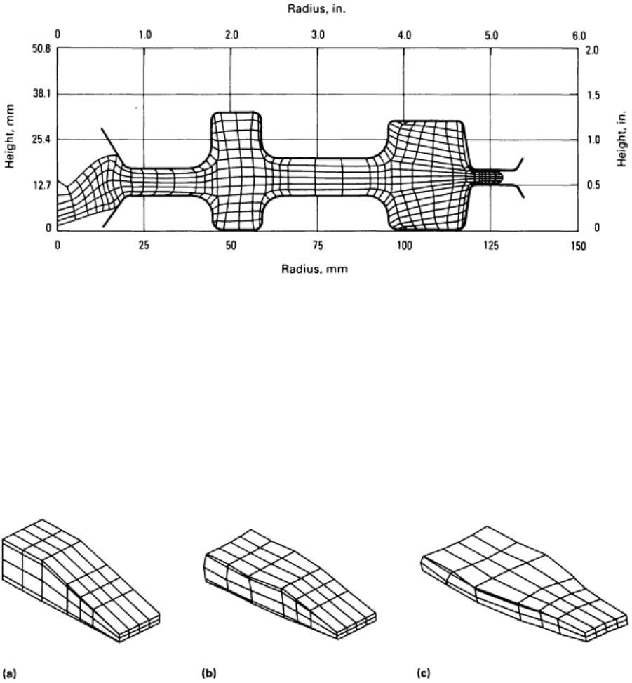
Fig. 16
ALPID simulation of final die position in the forging of a truck gear showing bending of flash that occurs
at the center of the part (left)
Three-Dimensional Wedge Deformation by Forging. Metal flow during a three-dimensional (3-D) deformation
process is illustrated in Fig. 17 (Ref 61, 62). The 3-D shape changes that occur during forging were accurately predicted
by the ALPID model. Careful examination of the deformation steps reveals that the specimen bulges at the anticipated
locations and rotates at the thin side of the tapered wedge. This simulation represents one of the first attempts at modeling
3-D metal flow during open-die design.
Fig. 17 Wedge formation simulated by 3-D finite-element modeling. Friction parameter m
' = 0.4. (a) 0%
reduction. (b) 30% reduction. (c) 60% reduction.
Powder Consolidation by Double-end Pressing. Double-end pressing (Fig. 18a) is generally used for the
consolidation of P/M forging preforms. To obtain quality preforms, density distributions along the length and across the
cross section must be controlled during consolidation. For this reason, ALPID 1.4 was utilized to predict density
distribution in this application (Fig. 18b).
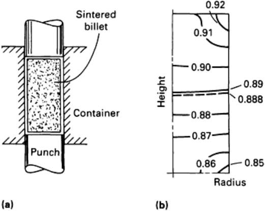
Fig. 18 Schematic showing double-end pressing process for the forging of P/M materials (a) and ALPID-
predicted relative density distribution in the forged billet (b). Initial relative density was 0.8; agreement with
actual density measurement (dashed line) was excellent.
Only one-fourth of the cylinder is shown in Fig. 18(b) because of the geometrical symmetry of the process. The excellent
agreement between predicted and observed results is worth noting. Figure 18(b) illustrates the density distribution
predicted by ALPID (solid contour lines), along with an experimental validation of the predictions (dashed contour lines).
Optimization of Ti-6Al-2Sn-4Zr-2Mo Disk-Forming Process. The approach of optimizing deformation
processes by using material-stability-preserving maps is demonstrated in the design of a Ti-6Al-2Sn-4Zr-2Mo disk-
forging process (Ref 58). The closed-die isothermal forging of this disk was previously analyzed using ALPID, with
emphasis on the prediction of metal flow near the flash (Ref 63). Because of symmetry, it is sufficient to analyze only one
quarter of the cross section of the forging. The predicted nodal-point velocity plots for 48, 68, and 72.1% reductions in
height are shown in Fig. 19. The plots clearly show the transition in metal flow from primarily upsetting deformation to
die cavity filling to the final stage of forming flash.
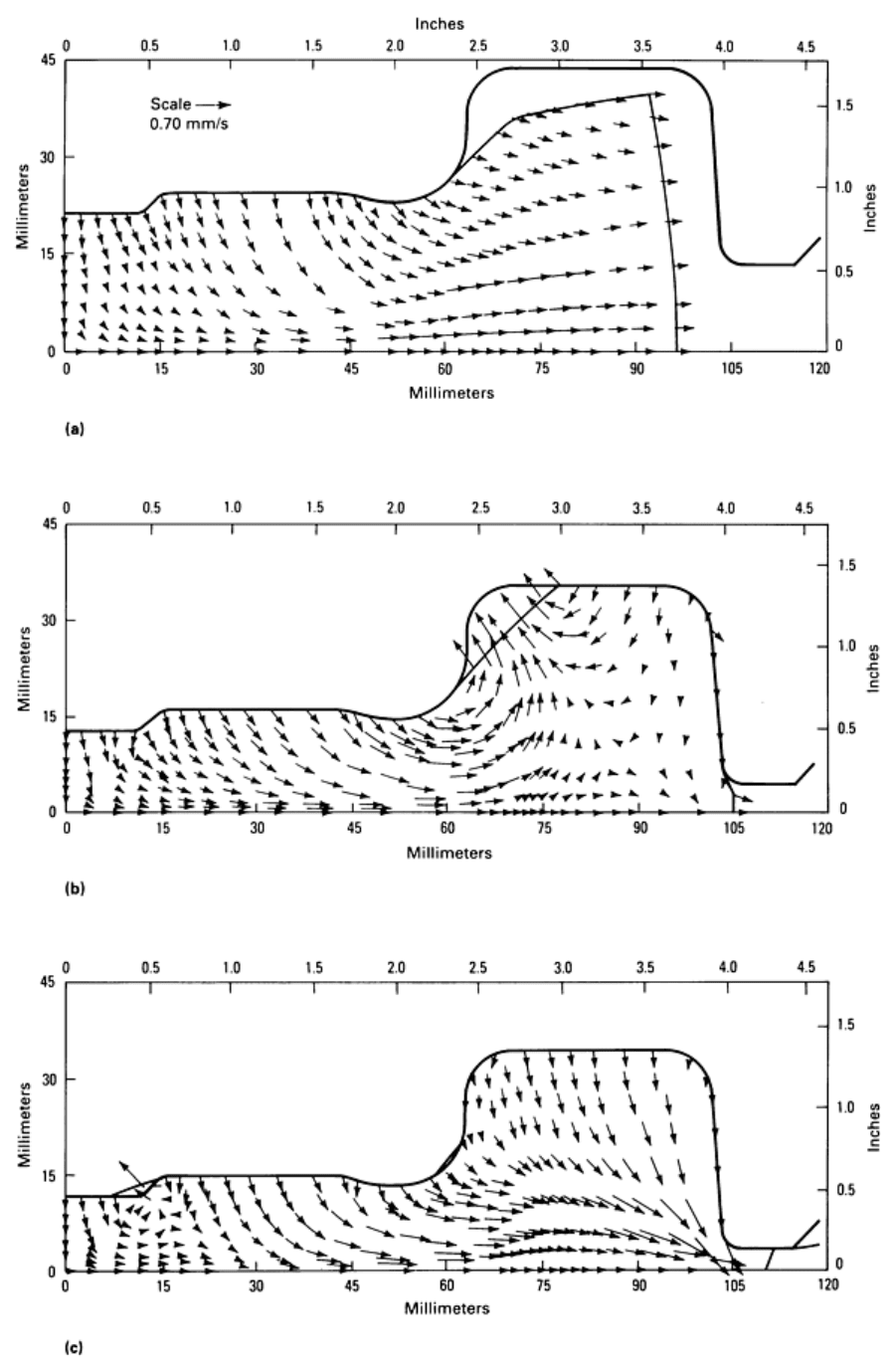
Fig. 19 Nodal-point velocity plots of disk-
forging simulation with constant die velocity at 48% (a), 68% (b),