ASM Metals HandBook Vol. 8 - Mechanical Testing and Evaluation
Подождите немного. Документ загружается.

(Eq 30)
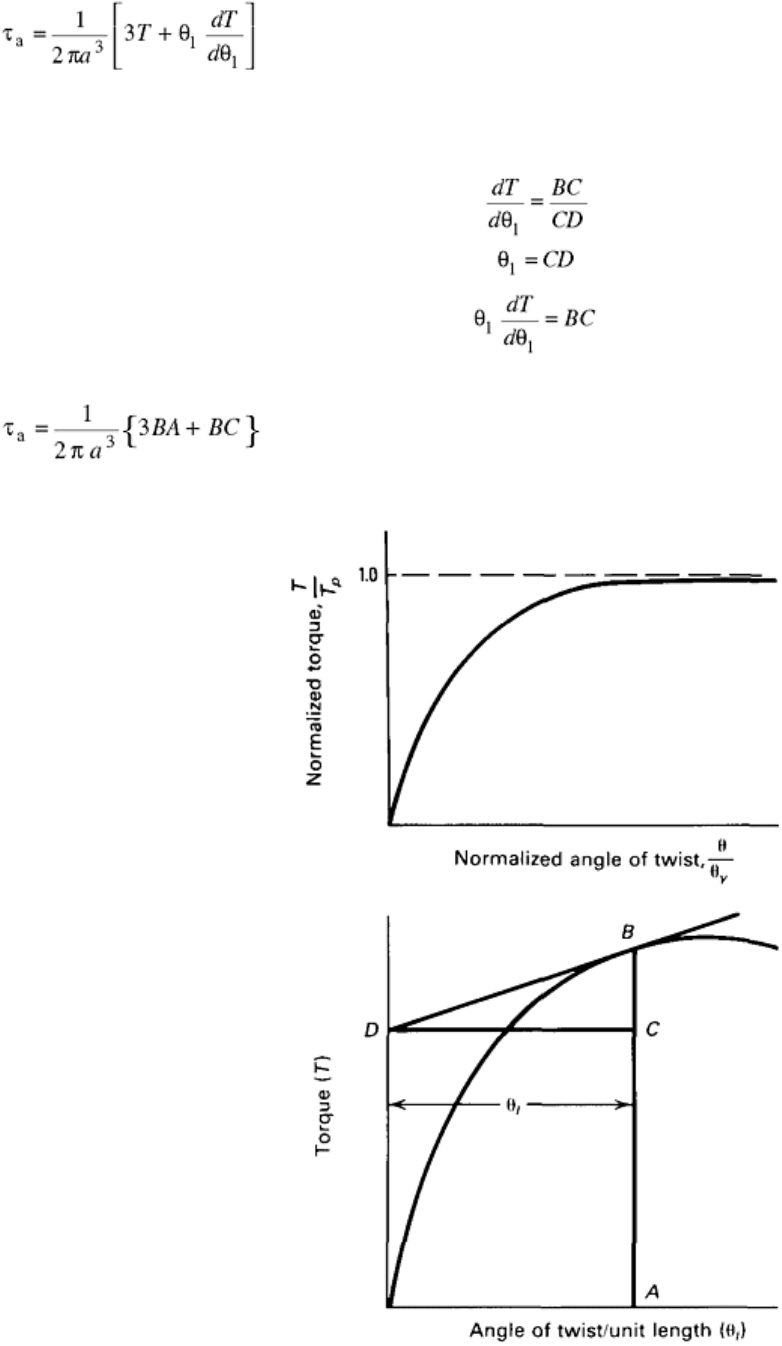
The first term on the right side of Eq 30 is the torque due to the maximum yield shear stress of τ
a
in a fully
plastic non-strain-hardening material, whereas the second term is a correction for strain hardening. These terms
can be readily derived from the torque-twist curve shown in Fig. 3, where:
so that:
(Eq 31)
The shear strain at the surface is given by Eq 28. Thus, the shear stress versus shear strain curve can be deduced
by drawing tangents to the torque versus the angle of twist per unit length curve.
Fig. 3 Torque-twist curves
In experimental work, it has often been found that the torque (T) is related to the angle of twist per unit length
by the expression:
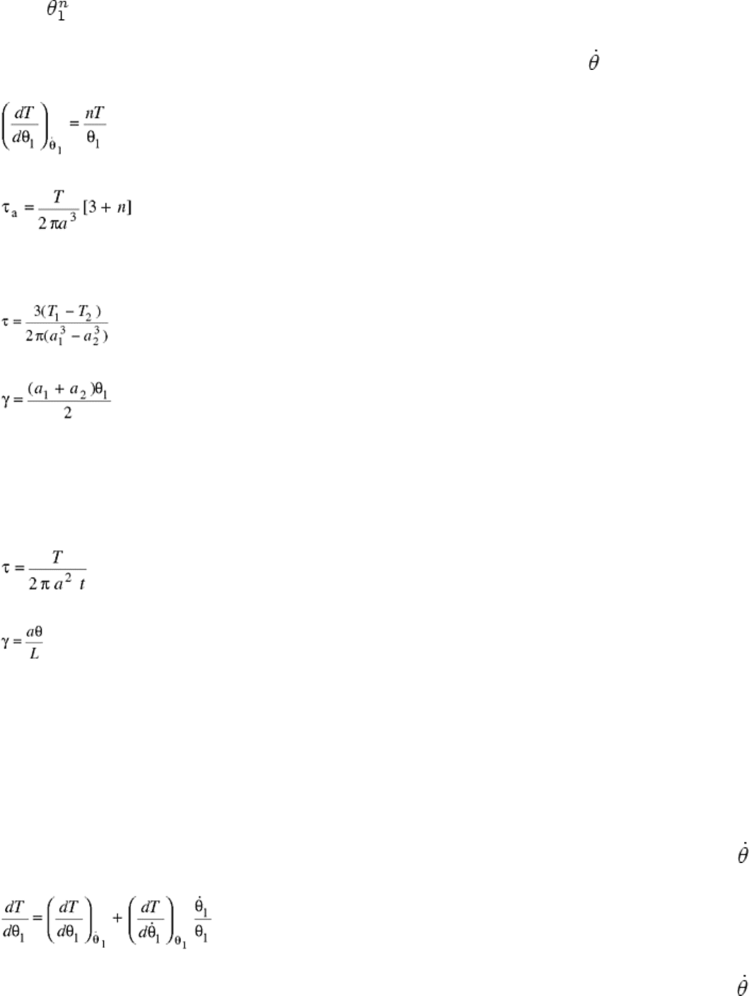
T = T
o
(Eq 32)
where T
o
is the torque at unit angle of twist, and n is the exponent. A graph of the logarithm of the torque (T)
versus the logarithm of the angle of twist per unit length (θ
1
) at constant rate of twist (
1
) is linear and of slope
n. Differentiating Eq 32 gives:
(Eq 33)
Combining Eq 30 and 33 gives:
(Eq 34)
This expression has been derived in Ref 3.
Shear stress versus shear strain curves may also be derived by the method of differential testing, where tests are
carried out on two specimens of slightly different radii, a
1
and a
2
. The shear stress and shear strain are given by:
(Eq 35)
and
(Eq 36)
respectively. An excellent critical review of existing methods for converting torque to shear stress is given in
Ref 5.
The stress gradient across the diameter of a solid bar allows the less highly stressed inner fibers to restrain the
surface fibers from yielding. Thus, the onset of yielding is generally not apparent. This effect can be minimized
by the use of thin-walled tubes, in which the stress across the tube wall can be assumed to be constant. For a
thin-walled tube, the shear stress and shear strain are given by:
(Eq 37)
and
(Eq 38)
respectively, where a is now the mean radius of the tube, t is the thickness of the tube wall, θ is the angle of
twist, and L is the specimen gage length. Thus, from measurements of the torque (T) and angle of twist (θ), it is
possible to construct the shear stress (τ) versus shear strain (γ) curve directly. The dimensions of the tube must
be chosen carefully to avoid buckling.
Effect of Strain Rate on Plastic Deformation. In the analysis presented in the previous section, it is inherently
assumed that the shear stress is independent of strain rate. The assumption is approximately valid at low
homologous temperatures, but is not valid at high homologous temperatures, where the strain-rate sensitivity of
materials is usually large. A graphical procedure for accounting for strain-rate effects is presented in Ref 3 and
6.
If it is assumed that the torque is a function of both the angle of twist and the twisting rate, that is, T = f (θ, ),
then the change in torque with respect to a change in the angle of twist is given by:
(Eq 39)
The first term on the right-hand side of this equation has been evaluated (Eq 33). The second term can be
evaluated from the experimental observation that a logarithmic graph of torque (T) versus the rate of twist (
1
)
at a constant angle of twist per unit length (θ)
l
is often linear. The slope of the graph corresponds to the twist-
rate sensitivity (m). Strain hardening predominates at low temperatures, whereas twist-rate sensitivity
predominates at elevated temperatures.
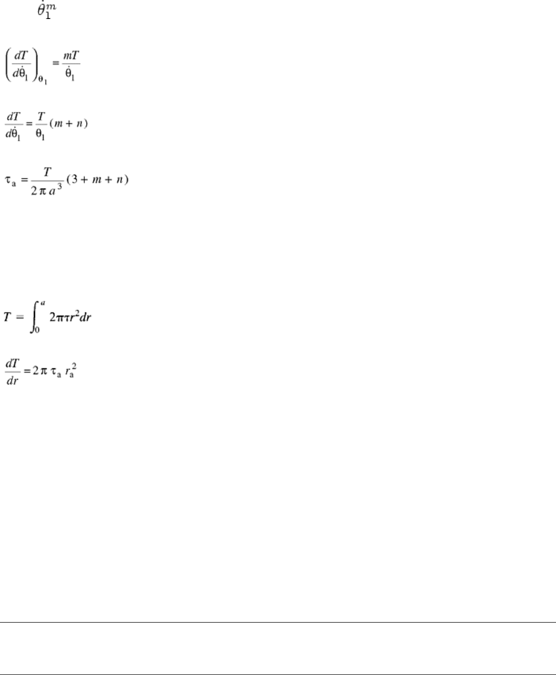
If the effect of twist rate on torque can be expressed by:
T = T
1
(Eq 40)
then, at constant strain:
(Eq 41)
Substitution of Eq 33 and 41 into Eq 39 gives:
(Eq 42)
Combining Eq 30 and 42 gives:
(Eq 43)
The shear strain is again given by:
γ = aθ
1
(Eq 44)
Equations 43 and 44 can be used to plot graphs of shear stress versus shear strain for all temperatures and strain
rates up to the point of torsional instability.
A new method of converting torque to surface shear stress (Ref 5) is based on the assumption that the shear
stress at radius r is affected only by the history of this particular location. The torque is given by:
(Eq 45)
The derivative of this integral at a given angle of twist and strain rate is:
(Eq 46)
In this method, torque versus angle of twist curves are determined on specimens of increasing radii from which
the torque versus radii relationship can be determined at a given strain (twist) and strain rate (twist rate). The
slope of this curve at any given radius can be substituted into Eq 46 to determine the current shear stress at this
radius. This method appears to reduce significantly the errors inherent in previous methods.
References cited in this section
3. W.J.McG. Tegart, Elements of Mechanical Metallurgy, Macmillan, 1967, p 64
4. A. Nadai, Theory of Flow and Fracture of Solids, Vol 1, McGraw-Hill, 1950, p 349
5. G.R. Canova, et al., Formability of Metallic Materials—2000 A.D., STP 753, J.R. Newby and B.A.
Niemeier, Ed., ASTM, 1982, p 189
6. D.S. Fields and W.A. Backofen, Proc. ASTM, Vol 57, 1957, p 1259
Fundamental Aspects of Torsional Loading
John A. Bailey, North Carolina State University;Jamal Y. Sheikh-Ahmad, Wichita State University
Effective Stresses and Strains
It is often helpful to convert data derived under one state of stress to another state of stress. This can be
accomplished by the use of so-called effective or tensile equivalent stresses and strains. The form of the
relationships from shear stresses and strains to effective stresses and strains depends on the particular yield
criterion used (Ref 7).
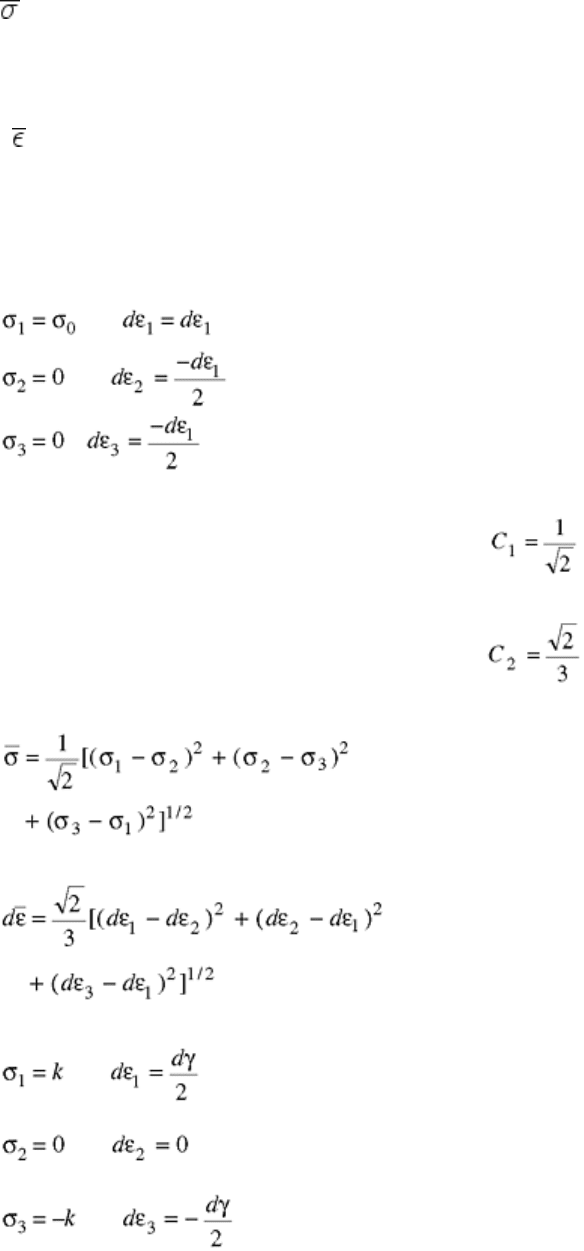
For the distortional energy (von Mises) criterion, the effective stress and strain are given by:
= C
1
[(σ
1
- σ
2
)
2
+ (σ
2
- σ
3
)
2
+ (σ
3
- σ
1
)
2
]
1/2
(Eq 47)
and
d = C
2
[(dε
1
- dε
2
)
2
+ (dε
2
- dε
3
)
2
+ (dε
3
- dε
1
)
2
]
1/2
(Eq 48)
respectively, where the variables have their usual significance (Ref 7). The constants C
1
and C
2
are now chosen
so that the effective stresses and strains are identical to the stresses and strains in uniaxial tension (or
compression). For uniaxial tension:
(Eq 49)
Substituting Eq 49 into Eq 47 and 48 gives:
and
Thus, the effective stresses and strains become:
(Eq 50)
and
(Eq 51)
respectively. For the state of pure shear (torsion):
(Eq 52)
Substitution of Eq 52 into 50 and 51 gives:
or
Thus, the effective stresses and strains are related to the shear stresses and strains by the factors and 1/ ,
respectively; that is, the shear stress versus shear strain curve can be converted to a true (tensile) stress versus
strain curve by using:
For the Tresca (maximum shear stress) criterion, the effective stresses and strains are given by:
= C
3
(σ
1
- σ
3
)
(Eq 53)
and
d = C
4
(dε
1
- dε
3
)
(Eq 54)
respectively (Ref 7). The constants C
3
and C
4
are again chosen so that the effective stresses and strains are
identical to the stresses and strains in uniaxial tension (or compression). Using the conditions defined by Eq 49
gives:
C
3
= 1
and
Thus, the effective stresses and strains become:
= (σ
1
- σ
3
)
(Eq 55)
and
(Eq 56)
Substitution of Eq 52 into Eq 55 and 56 gives:
= 2k
and
or
Thus, the effective stresses and strains are related to the shear stresses and shear strains by the factors 2 and ,
respectively; that is, the shear stress versus shear strain curve can be converted to a true (tensile) stress versus
strain curve by using:
σ = 2τ
(Eq 57)
and
(Eq 58)
The work of deformation per unit volume in terms of the effective stresses is given by:
u = ∫ d
(Eq 59)
The work of deformation in torsion can be calculated from the expressions:
(Eq 60)
and
(Eq 61)
for the Tresca (maximum shear stress) criterion and distortional energy criterion, respectively. For the Tresca
criterion, substitution of Eq 60 into Eq 59 gives:
(Eq 62)
For the distortional energy criterion, substitution of Eq 61 into Eq 59 gives:
(Eq 63)
It is evident that the work obtained by the Tresca criterion is too high and that the distortional energy criterion
gives the correct result.
Reference cited in this section
7. S. Kalpakjian, Mechanical Processing of Materials, D. Van Nostrand, 1967, p 31
Fundamental Aspects of Torsional Loading
John A. Bailey, North Carolina State University;Jamal Y. Sheikh-Ahmad, Wichita State University
Constitutive Relationships
Application to Metalworking Analyses. In the past, numerous techniques were developed for the analysis of
metalworking processes including slip-line field theory, upper and lower bound approaches, slab/disk/tube
approaches, viscoplasticity theory, and the method of weighted residuals (Ref 8). These techniques are usually
based on various simplifying assumptions that often severely restrict their usefulness. However, recent
advances in the development of numerical methods (e.g., finite element analysis) and computational techniques
have lead to the evolution of new tools for the analysis and design of metalworking processes. A key feature of
such tools should be their ability to calculate the influence of processing variables on forming loads, torques,
and power requirement as well as capturing a quantitative description of workpiece deformation. Inherent in
performing such calculations is knowledge of the effects of strain, strain rate, and temperature on the flow
stress of the work material. Such effects are described by a constitutive model that represents material behavior.
Effects of Strain, Strain Rate, and Temperature on Flow Stress. There is much evidence suggesting that the
torsion of hollow tubes of the appropriate dimensions (Ref 9) may be one of the better ways to obtain
information on the effect of strain, strain rate, and temperature on the flow stress of materials over the range of
these variables usually encountered in metalworking processes. Tests can be carried out to large strains over a
wide range of temperature and at constant true strain rates. In addition, the occurrence of frictional effects
(compression) and instability (tension) are absent.
The preceding sections present methods for obtaining the shear stress and shear strain from measures of the
torque and angle of twist. It is also shown that the shear stresses and shear strains could be readily converted
into effective stresses and strains. This section includes some simple relationships that relate the effective stress
to the effective strain, effective strain rate, and temperature.
The effective stress is often related to the effective strain by the expression:
= K( )
n
(Eq 64)
at constant strain rate and temperature, where K is a strength coefficient and n is the strain-hardening exponent.
A plot of log against log is usually linear and of slope n. The strength coefficient K is the value of the
effective stress at an effective strain of unity.
The effective stress is often related to the effective strain rate by the expression:
= C
1
( )
m
(Eq 65)
at constant strain and temperature where C
1
is a strength coefficient and m is the strain-rate sensitivity. A plot of
log against log is usually linear and of slope m. The strength coefficient is the value of the effective stress at
an effective strain rate of unity. The combined effect of strain and strain rate on the effective stress can often be
described by the expression:
= A( )
n
( )
m
(Eq 66)
at constant temperature where A is a strength coefficient. Graphical procedures based on experimental results
can be used to solve for the unknown constants.
The effective stress is often related to temperature by the expression:
= C
2
exp(Q/RT)
(Eq 67)
at constant strain and strain rate where C
2
is a strength coefficient, Q is the activation energy for plastic
deformation, and R is the universal gas constant. A plot of log against 1/T is often linear and of slope Q/R,
from which Q can be calculated. The value of the flow stress depends on the dislocation structure at the time at
which the flow stress is measured. However, dislocation structure may change with strain, strain rate, and
temperature. One way to minimize this effect is to evaluate Q using a temperature change test. Such tests are
carried out at constant strain rate and at a desired value of the plastic strain the temperature is changed from,
say, T
1
to T
2
, and the new stress (
2
) is measured (Ref 10).
The activation energy is then given by the expression:
(Eq 68)
The combined effect of strain rate and temperature on flow stress can often be described by the expression:
= f(Z)
(Eq 69)
at constant strain where Z is the Zener-Hollomon parameter and is given by the expression:
Z = exp(ΔH/RT)
(Eq 70)
where ΔH is an activation energy that is related to Q by the expression:
Q = m ΔH
(Eq 71)
In the past, Eq 69 was considered to be a mechanical equation of state. However, this is no longer regarded as
being valid (Ref 10).
In torsion tests and plane strain compression tests that are carried out to large strains, it is often found that
deformation occurs under steady-state conditions, and the flow stress attains a constant value, independent of
further straining. Such a condition is often encountered in many hot metalworking processes. It is then found
that stress, strain rate, and temperature are related by the well-known creep equation (Ref 11 and 12) that also
applies to steady-state deformation:
= A(sinh α )
n′
exp(-Q/RT)
(Eq 72)
where α, n′, and A are constants and the remaining symbols have their usual significance. At low stress (high
temperature) and high stress (low temperature), Eq 72 reduces to a power law:
= A
1
n′
exp(-Q/RT)
(Eq 73)
and an exponential law:
= A
2
exp(β )exp (−Q/RT)
(Eq 74)
respectively. It is found for many materials that linear relationships exist between log
e
and log
e
[sinh α ] at
constant temperature and between log
e
and 1/T at constant sinh α . The latter relationship enables the value
of Q to be determined. An alternative and simpler method for calculating Q is to recognize that Eq 72 can be
written in the form:
(Eq 75)
or
Q = 2.3R(n′)
T
(n″)
(Eq 76)
Linear relationships usually exist between log
e
and log
e
[sinh α ] and between log
e
[sinh α ] and 1/T at
constant temperature and strain rate, respectively. Data over a wide range of temperature in the hot-working
regime can be reduced to a single linear relationship by plotting log
e
[ exp Q/RT] versus log
e
[sinh α ] (Ref
13).
In some practical metalworking operations, steady-state deformation may not be achieved because temperatures
and plastic strains may be too low. Flow stress then depends upon strain, strain rate, and temperature. In these
situations, a general constitutive relation of the form:
[B
n
][1 + C log
c
/
o
]f( )
(Eq 77)
where B, n, and C are material constants has been found to be very useful (Ref 14, 15, 16). The quantity
(dimensionless temperature) is given by the expression:
= (T
m
- T)/(T
m
- T
o
)
(Eq 78)
where T
m
is the melting point temperature of the material, and
o
and T
o
are reference strain rates and
temperatures, respectively.
The first term in Eq 77 accounts for strain-hardening effects, the second term accounts for strain-rate effects,
and the third term accounts for temperature effects. Linear, bilinear, and exponential forms (Ref 16) of the term
f( ) have been used by many investigators. The advantage of the above constitutive relationship (model) is
that the effects of strain, strain rate, and temperature are uncoupled, which greatly simplifies the evaluation of
the constants from experimental data.
References cited in this section
8. E.M. Mielnik, Metal Working Science and Engineering, McGraw-Hill, 1991, p 220
9. J.A. Bailey, S.L. Haas, and M.K. Shah, Int. J. Mech. Sci., Vol 14, 1972, p 735

10. G. Dieter, Mechanical Metallurgy, 2nd ed., McGraw-Hill, 1976, p 353
11. F. Garafalo, Fundamentals of Creep and Creep Rupture of Metals, Macmillan, 1965
12. C.M. Sellars and W.J.McG. Tegart, Int. Met. Rev., Vol 7, 1972, p 1
13. J.J. Jonas, C.M. Sellars, and W.J.McG. Tegart, Met. Rev., Vol 130, 1969, p 14
14. G.R. Johnson and W.H. Cook, Proc. Seventh Int. Symp. Ballistics, 1983, p 541
15. G.R. Johnson, J.M. Hoegfeldt, U.S. Lindholm, and A. Nagy, J. Eng. Mater. Technol. (Trans. ASME),
Vol 105, 1983, p 42
16. G.R. Johnson, J.M. Hoegfeldt, U.S. Lindholm, and A. Nagy, J. Eng. Mater. Technol. (Trans. ASME),
Vol 105, 1983, p 48
Fundamental Aspects of Torsional Loading
John A. Bailey, North Carolina State University;Jamal Y. Sheikh-Ahmad, Wichita State University
Anisotropy in Plastic Torsion
Marked dimensional changes can occur during the torsional straining of solid bars and hollow cylinders of
circular cross section (Ref 7, 9, and 17). These changes may produce either an increase or a decrease in the
length of test specimens. Changes in length produced in hollow cylinders are considerably greater than those
produced in solid bars because of the constraining effect of the solid core with the latter geometry. If changes in
length are suppressed, then large axial stresses may be produced.
Dimensional changes have been attributed to the development of crystallographic anisotropy that arises because
of a continuous change in the orientation of individual grains. This produces preferred orientation, where the
yield stresses and macroscopic stress versus strain relationships vary with direction. The general observation is
that the torsional deformation of solid bars and tubes produces axial extension at ambient temperatures and
contraction that is often preceded by an initial period of lengthening, at elevated temperatures. Specific results,
however, depend on the initial state (anisotropy) of the test material.
Theory of Anisotropy. A general phenomenological theory of anisotropy (Ref 17) proposes that the criterion
describing the yield direction for anisotropic and orthotropic materials be quadratic in stress components and of
the form:
2 f(σ
ij
) = F(σ
y
- σ
z
)
2
+ G(σ
z
- σ
x
)
2
+ H(σ
x
- σ
y
)
2
+ 2Lτ
yz
+ 2M τ
zx
+ 2N τ
xy
(Eq 79)
where F, G, H, L, M, and N are six parameters describing the current state of anisotropy, f(σ)
ij
is the plastic
potential, and the remaining symbols have their usual significance. The set of axes used in this criterion is
assumed to be coincident with the principal axes of anisotropy. For an orthotropic material, the plastic
properties at a given point are symmetric with respect to three orthogonal planes whose intersection defines the
principal axes of anisotropy. It is clear that any practical application of this criterion requires prior knowledge
of the principal axes of anisotropy and the numerical values of F, G, H, L, M, and N.
The basic theory of anisotropy (Ref 17) has been applied to the torsional straining of a thin-walled cylinder in
an attempt to describe the changes in dimensions that occur. For a thin-walled cylinder, the radius is large
compared with the wall thickness, and thus anisotropy can be considered to be uniformly distributed throughout

the volume of the material deformed. It was also assumed that the axes of anisotropy along the surface of an
initially anisotropic cylinder were coincident with the directions of greatest accumulated tensile and
compressive strain. These axes were also assumed to be mutually perpendicular and oriented at an angle φ to
the transverse axis of the cylinder. This geometry is shown in Fig. 4. For an initially isotropic cylinder, the
angle φ is a function of the shear strain (γ) and increases from π/4, approaching π/2 at large strains. This
rotation is confined to the (x,y) plane about the z-axis that is perpendicular to the surface of the cylinder.
Fig. 4 Geometry of deformation for the plastic straining of a hollow cylinder. γ, shear
strain; L, initial length of cylinder; OC, initial direction of greatest compression; OC′,
final direction of greatest compression; OE, initial direction of greatest extension; OE′,
final direction of greatest extension
From an analysis of the deformation, it was shown that the change in axial strain with shear strain is given by:
(Eq 80)
It is clear from Eq 80 that measurement of the change in axial strain with shear strain is insufficient to
determine the anisotropic parameters and yield stresses along the anisotropic axes and thereby insufficient to
describe quantitatively the state of anisotropy. Simple expressions for the variation of the anisotropic
parameters and yield stresses along the anisotropic axes with shear strain have been developed in terms of the
changes in axial strain, tangential strain, principal yield shear stress, and through thickness yield stress of the
hollow cylinder (Ref 18), all of which can be determined easily by experiment. It was found that the anisotropic
parameters decrease and that the yield stresses along the anisotropic axes increase with an increase in strain,
eventually becoming independent of strain when the test material is fully work hardened.
Montheillet and his coworkers (Ref 19, 20) modified Hill's theory of anisotropy by aligning the principal axes
of anisotropy with the 〈100〉 directions of the ideal orientation prevailing in a polycrystal. Following the
alignment, an optimization process was carried out such that the modified yield surface gives a good fit to the
crystallographic yield surface of the single crystal representing the ideal orientation. The anisotropic parameters
can then be determined. A direct relationship between the axial forces generated (positive, negative, zero) and
the crystallographic texture developed for several materials was proposed. The sign and approximate magnitude
of the effects was predicted from knowledge of the ideal orientation.
Utilizing the rate-sensitive theory of crystal plasticity based on glide modeling, a number of researchers have
succeeded in developing computer models that are capable of predicting and explaining the evolution of texture
and the subsequent lengthening and axial compressive stresses that develop during free-end and fixed-end
twisting, respectively. A brief review of this work is given in Ref 21. Glide-modeling methods alone, however,
are not capable of predicting and explaining the shortening behavior noted at elevated temperatures. A more
plausible explanation of this phenomenon was provided by taking into account the occurrence of dynamic
recrystallization (DRX) at elevated temperatures. In a series of recent studies (Ref 22, 23, and 24), Toth, Jonas,
and coworkers were able to characterize and model the texture developed during the free-end hot torsion of