AWS B4.0: 2007 Standard Methods for Mechanical Testing of Welds
Подождите немного. Документ загружается.

CLAUSE 5. SHEAR TESTS AWS B4.0:2007
14
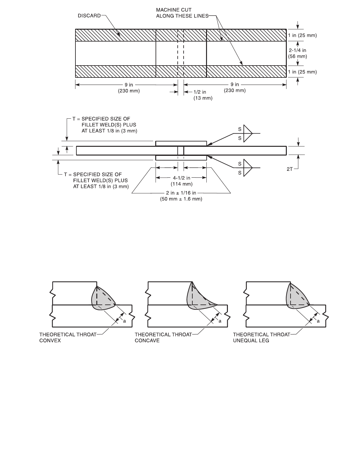
Figure 5.2—Transverse Fillet Weld Shear Specimen
τ =
where
P=load
l = total length of fillet weld sheared
a = theoretical throat dimension
τ = shear strength of weld
Figure 5.3—Shear Strength Calculation
P
l
a×
-----------
Copyright American Welding Society
Provided by IHS under license with AWS
Not for Resale
No reproduction or networking permitted without license from IHS
--`,,```,,,,````-`-`,,`,,`,`,,`---

AWS B4.0:2007 CLAUSE 6. BEND TESTS
15
6. Bend Tests
6.1 Scope
6.1.1 This clause covers the bend testing of fillet
welds, groove welds in butt joints and the bend testing of
surfacing welds. The standard gives the requirements for
bend test specimen preparation, test parameters, and test-
ing procedures, but does not specify acceptance criteria.
6.1.2 The base materials may be homogenous, clad or
otherwise surfaced, except for hardfacing.
6.1.3 This standard is applicable to the following,
where specified:
(1) Qualification of materials, welding personnel, and
welding procedures;
(2) Information, specifications of acceptance, manu-
facturing quality control; and
(3) Research and development.
6.1.4 When this standard is used, the following infor-
mation shall be specified:
(1) The specific location and orientation of the
specimens;
(2) The specific types of tests, for example, face bend,
side bend, or root bend and number of specimens
required;
(3) Bend radius and specimen thickness (T), or per-
cent (%) elongation. When not otherwise specified, the
elongation is generally determined by the base metal or
filler metal requirement, whichever is lower; and
(4) Postweld thermal or mechanical processing treat-
ments, as applicable.
6.2 Normative References. The following standards
contain provisions which, through reference in this text,
constitute mandatory provisions of this test. For undated
references, the latest edition of the referenced standard
shall apply. For dated references, subsequent amend-
ments to, or revisions of, any of these publications do not
apply.
ASME Documents:
ASME B46.1, Surface Texture, Surface Roughness,
Waviness and Lay
ASTM Documents:
ASTM A 370, Standard Test Methods and Definitions
for Mechanical testing of Steel Products
ASTM E 190, Standard Test Method for Guided Bend
Test for Ductility of Welds
6.3 Definitions and Symbols. For the purposes of this
test, the following definitions and symbols apply:
A = plunger or mandrel radius
B =die radius
e = elongation of outer surface
ID = inside diameter
L = test plate length
R = radius
S = surfacing weld thickness
T = specimen thickness
t = thickness of test weldment
W = specimen width
6.4 Summary of Method
6.4.1 Specimens are guided in the bending process by
a test fixture that employs a mandrel with wraparound
roller or end supports with a plunger.
6.4.2 Maximum strain on the tension surface is con-
trolled by the thickness of the specimen and the radius of
the mandrel or plunger.
6.5 Significance
6.5.1 The ductility of the welded joint, as evidenced
by its ability to resist tearing and the presence of defects
on the tension surface, is determined in a guided bend
test.
6.5.2 Bend tests of weld cladding are used to
detect incomplete fusion, tearing, delamination, macro-
discontinuities, and the effect of bead configuration.
6.6 Apparatus
6.6.1 Guided bend specimens may be tested in either
of two types of fixture. One type is the guided bend fix-
ture, which is designed to support and load the specimen
in a three point bending mode. The alternate is a wrap-
around bend fixture that fixes one end of the specimen
and uses a roller to force the specimen to bend around a
mandrel.
6.6.2 The guided bend fixture shall have the dimen-
sions given in Figure 6.1, 6.2, or 6.10.
6.6.3 The wraparound bend fixture shall have the
dimensions given in Figure 6.3.
6.6.4 The radius of the plunger, A, shown in Figures
6.1 and 6.2 or the mandrel shown in Figure 6.3 shall be
specified or determined from the following equation:
A = T(50/e – 1/2)
where
A = Radius of mandrel or plunger, ±1/16 in
(±1.6 mm);
Copyright American Welding Society
Provided by IHS under license with AWS
Not for Resale
No reproduction or networking permitted without license from IHS
--`,,```,,,,````-`-`,,`,,`,`,,`---

CLAUSE 6. BEND TESTS AWS B4.0:2007
16
e = Elongation at outer surface, % ±1%; and
T = Specimen thickness, ±1/64 in (±0.40 mm).
6.6.5 The tolerances specified are for machining and
to allow use of standard size mandrels and plungers. It is
not the intent of the tolerances to purposely increase the
minimum bend radius beyond the calculated value.
6.7 Specimens
6.7.1 Bend test specimens shall be prepared by cutting
the weld and the base metal to form a specimen rectangu-
lar in cross section. For transverse bends, the surfaces cut
transverse to the weld shall be designated as the sides of
the specimen. For longitudinal specimens, the longitudi-
nal surfaces that were cut to form the specimen shall be
designated as the sides of the specimen and may or may
not contain any weld metal. Of the two remaining full-
length surfaces, the surface with the greatest weld face
width shall be designated as the face while the remaining
full length surface shall be designated as the root. Trans-
verse specimens may have the side, face, or root of the
weld as the tension surface. Longitudinal specimens may
have the face or the root of the weld as the tension sur-
face of the specimen.
6.7.2 When specimens wider than 1.5 in (38 mm) are
to be bent, the mandrel or plunger shall be at least 0.25 in
(6 mm) wider than the specimen width.
6.7.3 It is generally recommended that bend test
specimen thickness, T, be 3/8 in ± 1/64 in (10 mm ±
0.40 mm) unless otherwise dictated by the material thick-
ness, available equipment, or the applicable specification.
6.7.4 Transverse Side Bend. The longitudinal axis of
the specimen is perpendicular to the weld, and the speci-
men is bent so that one of the side surfaces becomes the
tension surface of the specimen. The side showing the
more significant discontinuities (if any) shall be the ten-
sion side. Transverse side bend test specimens shall con-
form to Figure 6.4. Transverse side bend specimens are
used for plates or pipe that are too thick for face bend or
root bend specimens and are recommended for welds
with narrow fusion zones.
6.7.5 Transverse Face Bend. The longitudinal axis
of the specimen is perpendicular to the weld and the
specimen is bent so that the weld face becomes the ten-
sion surface of the specimen. Transverse face bend spec-
imens shall conform to the requirements of Figure 6.5 for
plate and Figure 6.6 for pipe welds.
6.7.6 Transverse Root Bend. The longitudinal axis
of the specimen is perpendicular to the weld and the
specimen is bent so that the root surface of the weld
becomes the tension surface of the specimen. Transverse
root bend specimens shall conform to the requirements
of Figure 6.5 for plate and Figure 6.6 for pipe welds.
6.7.7 Longitudinal Face Bend. The longitudinal axis
of the specimen is parallel to the weld and the specimen
is bent so that the face of the weld becomes the tension
surface of the specimen. Longitudinal face bend speci-
mens shall conform to the requirements of Figure 6.7.
6.7.8 Longitudinal Root Bend. The longitudinal axis
of the specimen is parallel to the weld and the specimen is
bent so that the root of the weld becomes the tension sur-
face of the specimen. Longitudinal root bend test speci-
mens shall comply with the requirements of Figure 6.7.
6.7.9 Fillet Weld Root Bend. The fillet weld root-
bend test sample shall be welded and prepared as shown
in Figure 6.8. The root of the weld shall be the tension
surface of the specimen. The fillet weld root bend test is
an alternate to the fillet weld break test in some codes
and specifications (see 9.2).
6.7.10 Surfacing Weld Specimens. The face bend
and side bend specimens for surfacing welds shall
conform to the requirements of Figure 6.9. The length of
the transverse bend specimen shall be perpendicular to the
weld direction; the length of the longitudinal bend speci-
men shall be parallel to the weld direction. The surface
weld shall be the tension surface of the face bend specimen.
6.7.11 Longitudinal Fillet Weld Specimen. The fil-
let weld bend test specimens are prepared by making two
fillet welds on a T-joint and machining the specimen as
shown in Figure 6.10. The fillet weld shall be the tension
surface of the specimen.
6.8 Procedure
6.8.1 Unless otherwise specified, the specimen shall
be tested at ambient temperature and deformation shall
occur in a time period no shorter than 15 seconds and no
longer than 2 minutes. If weld and heat-affected zone
(HAZ) for transverse specimens are not within the
curved portion of the specimen, the specimen shall be
discarded and another specimen prepared and tested.
6.8.2 Guided Bend Testing
6.8.2.1 Transverse Specimens. The following
procedure is applicable to guided bend testing of trans-
verse specimens:
(1) Place the tension side down on the supporting sur-
face of the bend fixture shown in Figures 6.1, 6.2, and
6.10. The weld shall be centered in the fixture with the
centerline of the weld within 1/16 in (1.6 mm) of the
center of the fixture.
(2) Any means may be used for smoothly moving the
plunger in relation to the support members of the bend
fixture.
Copyright American Welding Society
Provided by IHS under license with AWS
Not for Resale
No reproduction or networking permitted without license from IHS
--`,,```,,,,````-`-`,,`,,`,`,,`---

AWS B4.0:2007 CLAUSE 6. BEND TESTS
17
(3) For bend fixtures with a bottom open (Figures 6.1
and 6.10), apply a sufficient load on the plunger until the
specimen is bottom ejected, or until the radius of the
plunger has cleared the radius of the rollers (or shoul-
ders). Caution must be used to prevent injury due to
the force of the ejecting specimen.
(4) For bend fixtures with a bottom radius (Figure
6.2), the plunger shall force the specimen into the die
until the specimen reaches the bottom of the fixture.
6.8.2.2 Longitudinal Specimens. The following
procedure is applicable to guided bend testing of longitu-
dinal specimens:
(1) Center the tension side of the specimen on the sup-
porting surfaces of the bend fixture.
(2) Proceed as described in 6.8.2.1(2) and (3) above
for transverse specimens.
6.8.3 Wraparound Bend Testing. The specimen
shall be firmly clamped on one end in the fixture (Figure
6.3) so that there is no sliding of the specimen relative to
the mandrel during the bending operation. Alternatively,
the specimen may be held stationary against a rotated,
nonslipping mandrel of radius A by a stationary compres-
sive roller. In this case the specimen is wrapped around
the rotating mandrel by draw-bending the specimen from
between the outer roller and the point where the rotating
mandrel holds the specimen tight against the roller. For
transverse bend specimens the weld and HAZs shall be
centered within the bent portion of the specimen. Test
specimens shall not be removed from the fixture until the
point where the outer roller contacts the bend specimen
and has moved 180° from its starting point along the
convex surface of the bend specimen.
6.8.4 Specimen Inspection. The specimen shall be
removed from the bend fixture and the tension surface of
the specimen (weld metal and HAZ) visually examined
for tears or other open defects, and all defect types, quan-
tities, sizes, and locations shall be recorded. When frac-
ture of the weld specimen occurs prior to completing a
180° bend, the angle at which it fractured shall be
recorded, if possible. For transverse bend specimens the
weld and HAZ shall be centered and completely within
the bent portion of the specimen after testing.
6.9 Report. In addition to the requirements of applicable
documents, the report shall include the following:
(1) Materials Identification
(a) Base metal specification
(b) Filler metal specification
(2) Specimen thickness and width
(3) Type of welded joint or surfacing weld
(4) Welding procedure specifications and procedure
qualification record numbers (if applicable) including
any supplemental information
(5) Specific tests performed
(6) Bend radius
(7) Test temperature
(8) Number of tests per condition or lot
(9) The following additional information should be in-
cluded: number, type, size and location of defects, if any
(10) Bend angle; also identify if specimen fractures
prior to 180°
(11) Any observation of unusual characteristics of the
specimens or procedure
6.10 Commentary
6.10.1 When testing weld specimens containing base
metal and filler metal which have significantly different
tensile and yield strengths, using the test fixtures shown
in Figures 6.1 and 6.2, bending will not be uniformly dis-
tributed across the weld, HAZ, and base metal. For
example, if the deposited weld metal has a yield strength
less than that of the base metal, yielding will begin in the
weld first, resulting in a true bend radius less than that of
the plunger. A smaller effective bend radius results in a
more severe test of the deposited weld metal.
On the other hand, when the deposited weld metal is
stronger than the base metal, bending will begin in the
HAZ and adjacent base metal, resulting in bending with
a small radius at these points and little, if any, bending
occurring in the weld metal. The result of this situation is
a more severe test of the HAZ or base metal and a less
severe test of the weld metal.
It is recommended that a wraparound fixture shown in
Figure 6.3 be used in these situations or longitudinal
bend specimens be used in place of the transverse guided
bend specimens. Testing of welds in dissimilar metals
(such as high tensile strength plate to ordinary structural
grade steels) can produce similar effects because of the
tendency for the specimens to shift (slide sideways) dur-
ing loading when using the fixtures shown in Figures 6.1
and 6.2. The use of a mallet to adjust the specimen in the
fixture after the specimen has begun bending is discour-
aged as it may result in rapid bending and undue failure.
6.10.2 For welds and materials with elongation
exceeding 20%, bend testing at 20% elongation is nor-
mally considered sufficient. This takes into consideration
the complexity of the welded joint and common require-
ments for weld strength. However, when elongation
greater than 20% is required for serviceability of the
joint, the contracting parties must specify the minimum
acceptable elongation for the bend test.
Copyright American Welding Society
Provided by IHS under license with AWS
Not for Resale
No reproduction or networking permitted without license from IHS
--`,,```,,,,````-`-`,,`,,`,`,,`---
CLAUSE 6. BEND TESTS AWS B4.0:2007
18
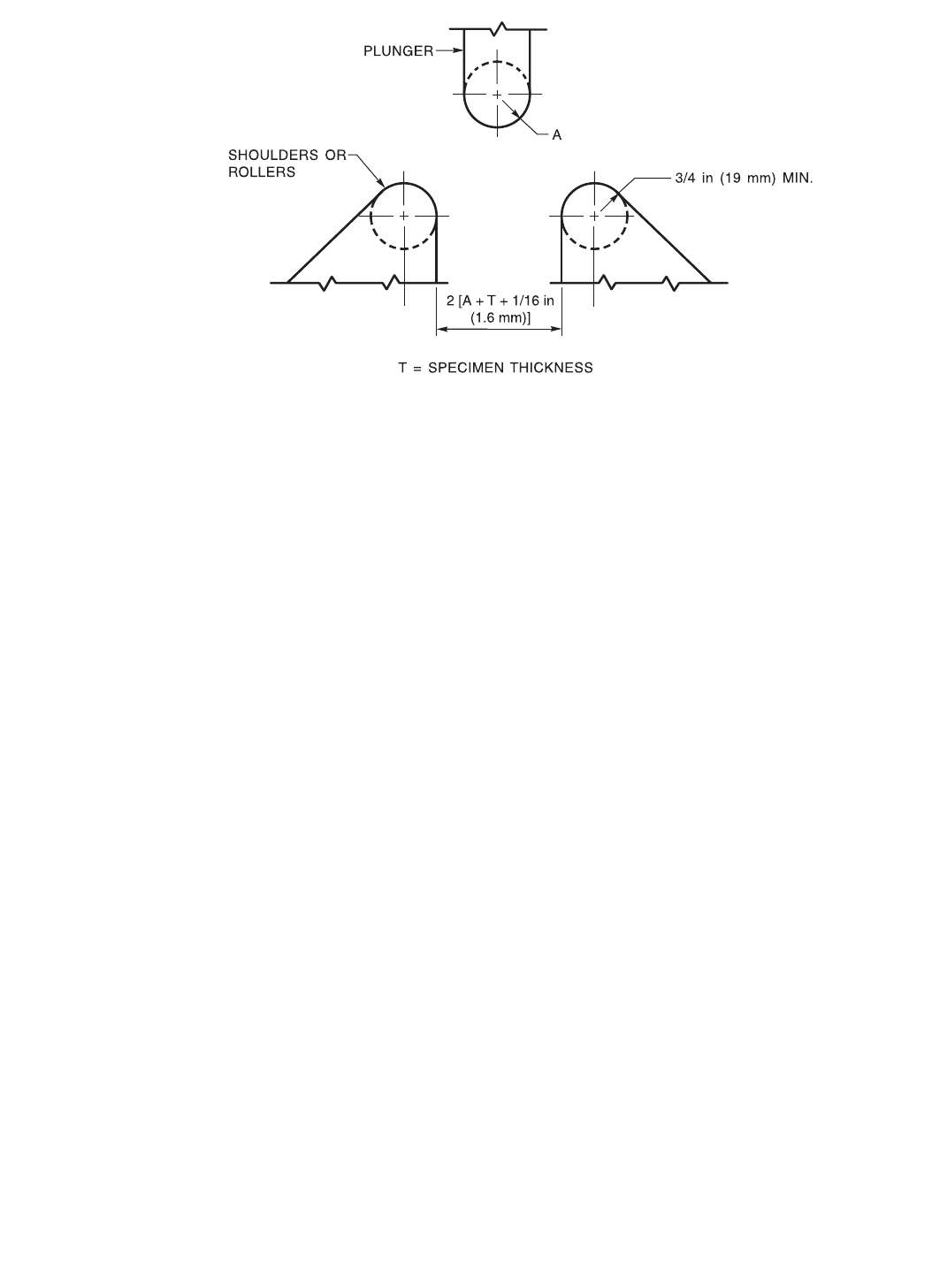
Notes:
1. Either hardened and greased shoulders or hardened rollers free to rotate shall be used.
2. The shoulder or rollers shall have a minimum bearing length of 2 in (50 mm) for placement of the specimen.
3. The shoulders or rollers shall be high enough above the bottom of the fixture so that the specimen will clear the shoulders or rollers
when the plunger is in the low position.
4. The plunger shall be fitted with an appropriate base and provision for attachment to the testing machine and shall be designed to
minimize deflection or misalignment.
5. The shoulder or roller supports may be made adjustable in the horizontal direction so that specimens of various thickness may be
tested in the same bend fixture.
6. The shoulder or roller supports shall be fitted to a base designed to maintain the shoulders or rollers centered and aligned with
respect to the plunger, and minimize deflection or misalignment.
7. The maximum plunger radius, A, shall be as specified or as determined from the formula in 6.6.4.
Figure 6.1—Typical Bottom Ejecting Guided Bend Test Fixture
Copyright American Welding Society
Provided by IHS under license with AWS
Not for Resale
No reproduction or networking permitted without license from IHS
--`,,```,,,,````-`-`,,`,,`,`,,`---
AWS B4.0:2007 CLAUSE 6. BEND TESTS
19
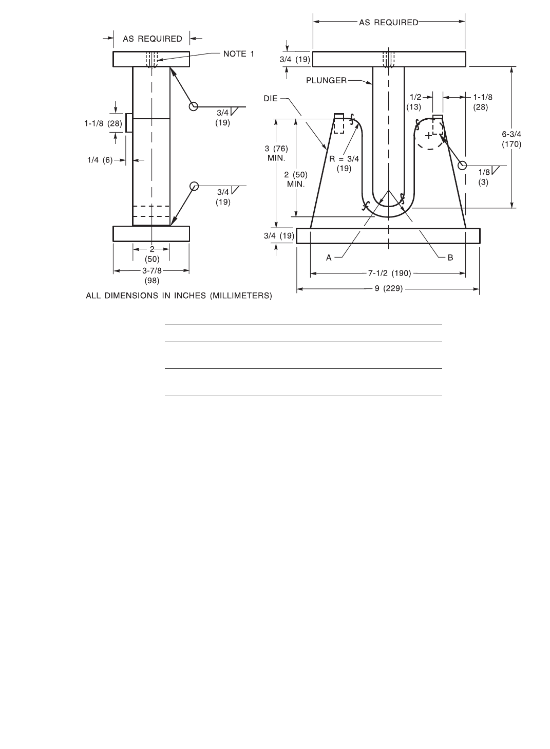
Notes:
1. Tapped hole of appropriate size, or other suitable means for attaching plunger to testing machine.
2. Either hardened and greased shoulders or hardened rollers free to rotate shall be used in die.
3. The plunger and its base shall be designed to minimize deflection and misalignment.
4. The plunger shall force the specimen into the die until the specimen becomes U-shaped. The weld and heat-affected zones shall be
centered and completely within the bent portion of the specimen after testing.
5. For a given specimen thickness, T, the maximum plunger radius, A, shall be as specified or as determined from the formula in 6.6.4.
For example, fixture dimensions for 20% elongation and a specimen thickness, T, of 3/8 in (10 mm) shall be plunger radius, A, equal
to 3/4 in (19 mm) and die radius, B, equal to 1-3/16 in (32 mm).
6. Weld sizes indicated are recommendations. The actual fillet weld size is the responsibility of the user to ensure rigidity and design
adequacy.
Figure 6.2—Typical Bottom Guided Bend Test Fixture
Fixture Dimensions for 20% Elongation of Weld
Specimen Thickness, T
in (mm)
Plunger Radius, A
in (mm)
Die Radius, B
in (mm)
3/8 (10) 3/4 (19) 1-3/16 (32)
T 2T A + T + 1/16 (1.6)
Copyright American Welding Society
Provided by IHS under license with AWS
Not for Resale
No reproduction or networking permitted without license from IHS
--`,,```,,,,````-`-`,,`,,`,`,,`---
CLAUSE 6. BEND TESTS AWS B4.0:2007
20
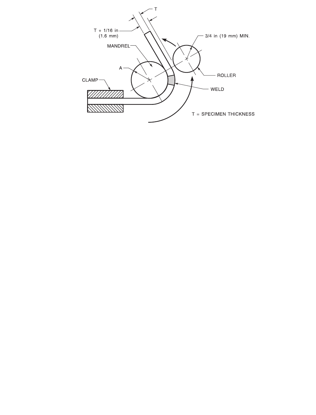
Notes:
1. Radius A shall be as specified, or as determined from the formula in 6.6.4. Dimensions not shown are the option of the designer,
except that the minimum width of the components shall be 2 in (50 mm).
2. It is essential to have adequate rigidity so that the bend fixture will not deflect during testing. The specimen shall be firmly clamped on
one end so that it does not slide during the bending operation.
3. Test specimens shall be removed from the bend fixture when the roller has traversed 180° from the starting point.
Figure 6.3—Typical Wraparound Guided Bend Test Fixture
Copyright American Welding Society
Provided by IHS under license with AWS
Not for Resale
No reproduction or networking permitted without license from IHS
--`,,```,,,,````-`-`,,`,,`,`,,`---
AWS B4.0:2007 CLAUSE 6. BEND TESTS
21
Notes:
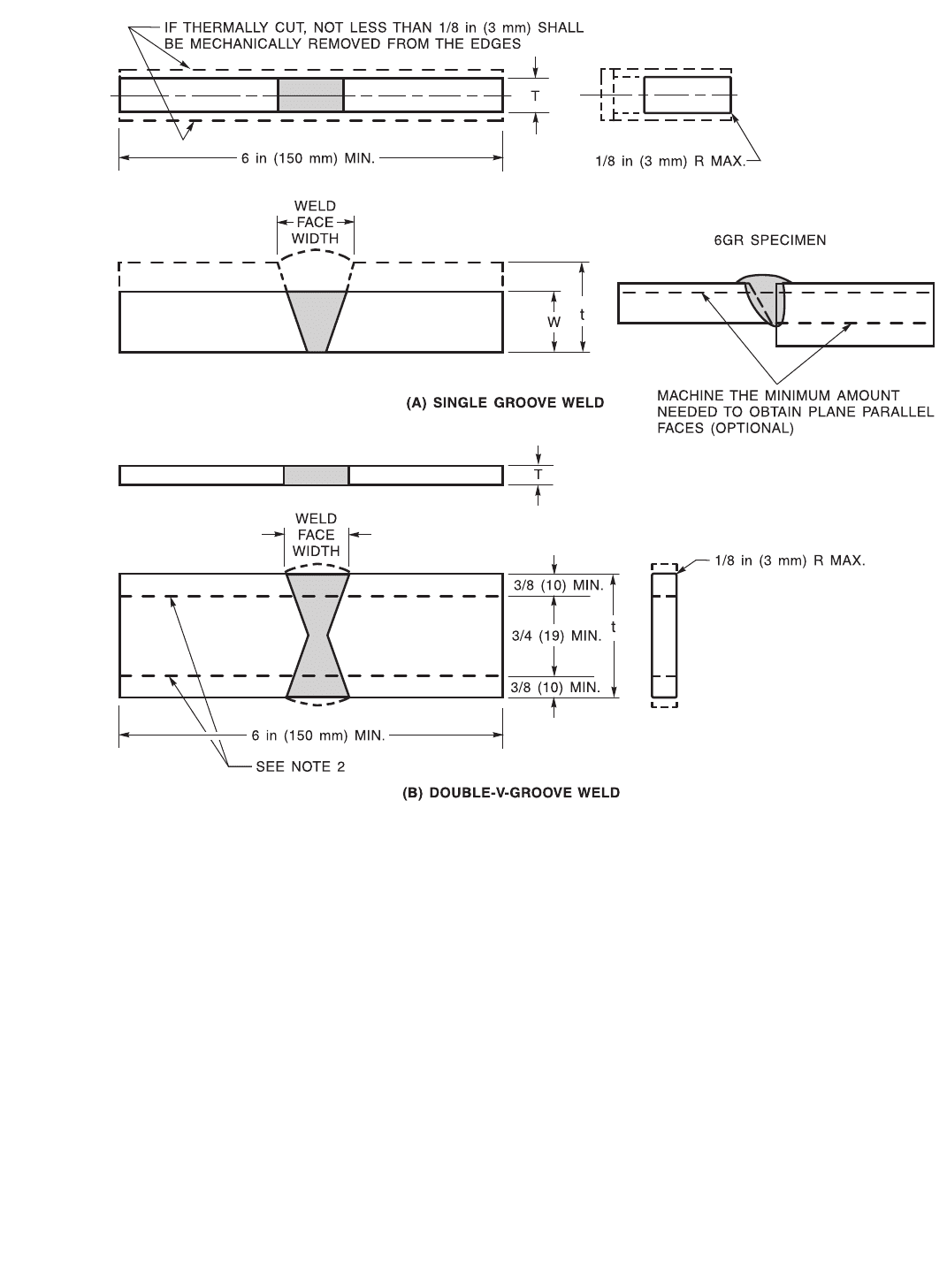
1. If the thickness, t, of a single-groove weld joint exceeds 1-1/2 in (38 mm), the specimen may be cut into approximately equal strips
between 3/4 in (19 mm) and 1-1/2 in (38 mm) wide. Each strip shall be tested by bending to the same radius as specified or as
determined by the formula in 6.6.4.
2. If the plate thickness, t, of a double-groove weld joint exceeds 1-1/2 in (38 mm), the specimen may be cut into multiple strips so that
the root of the weld is centered in one of the strips as shown. Whenever possible it is recommended that the specimen thickness, T,
be approximately 3/8 in (10 mm) with each specimen having a width exceeding its thickness. These strips shall be bent to the same
radius as specified or as determined by the formula in 6.6.4.
3. The weld reinforcement and backing, if any, shall be mechanically removed flush with the specimen surface. For performance
qualification, if sufficient material is available, acceptable undercut should be removed while maintaining specimen dimensions.
4. The diameter of the test plunger should be equal to or exceed the width of the remaining weld face width in order to test the weld HAZ and
base metal. If this requirement cannot be met, a greater thickness, T, may be chosen in accordance with the formula in 6.6.4.
5. All longitudinal surfaces shall be no rougher than 125 microinches (3 micrometers) R
a
. It is recommended that the lay of the surface
roughness be oriented parallel to the longitudinal axis of the specimen.
Figure 6.4—Transverse Side Bend Specimens (Plate)
Copyright American Welding Society
Provided by IHS under license with AWS
Not for Resale
No reproduction or networking permitted without license from IHS
--`,,```,,,,````-`-`,,`,,`,`,,`---
CLAUSE 6. BEND TESTS AWS B4.0:2007
22
Notes:
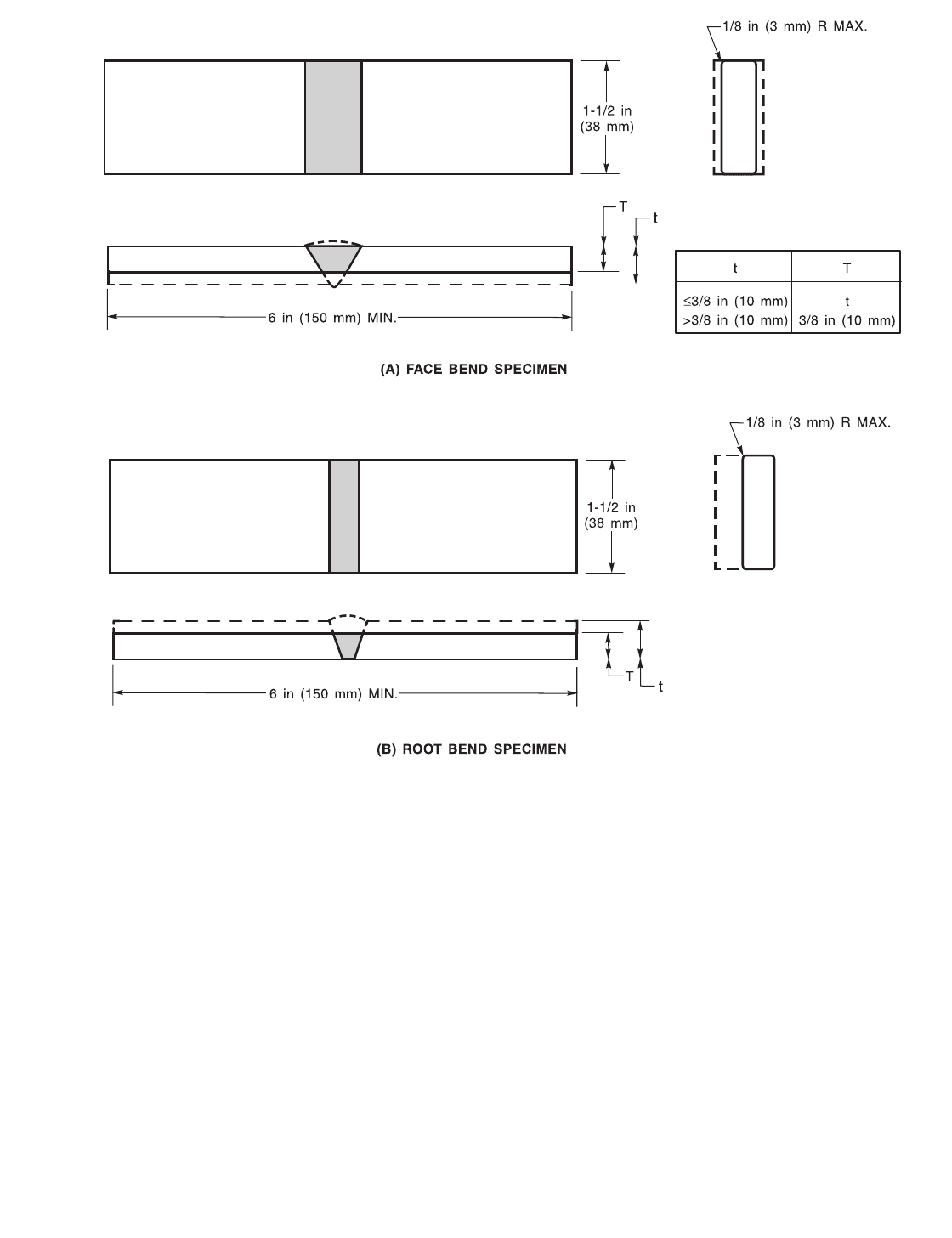
1. The specimen edges may be thermally cut but, in this case, at least 1/8 in (3 mm) of material shall be mechanically removed from the
thermally cut surface.
2. For clad metals having an elongation requirement of at least 25%, the specimen thickness, T, may be reduced when using a fixed
bend-radius testing bend fixture. The specimen thickness shall be determined by the formula in 6.6.4.
3. If the weld joins base metals of different thicknesses, the specimen should be reduced to a constant thickness based on the thinner
base metal.
4. Unless otherwise specified, the weld reinforcement and backing, if any, shall be mechanically removed flush with the specimen
surface. For performance qualification, if sufficient material is available, acceptable undercut should be removed while maintaining
specimen dimensions.
5. The diameter of the test plunger should be equal to or exceed the width of the remaining weld face. If this requirement cannot be met,
a greater thickness, T, may be chosen in accordance with the formula in 6.6.4.
6. All longitudinal surfaces shall be no rougher than 125 microinches (3 micrometers) R
a
. It is recommended that the lay of the surface
roughness be parallel to the longitudinal axis of the specimen.
Figure 6.5—Transverse Face Bend and Root Bend Specimen (Plate)
Copyright American Welding Society
Provided by IHS under license with AWS
Not for Resale
No reproduction or networking permitted without license from IHS
--`,,```,,,,````-`-`,,`,,`,`,,`---
AWS B4.0:2007 CLAUSE 6. BEND TESTS
23
Notes:
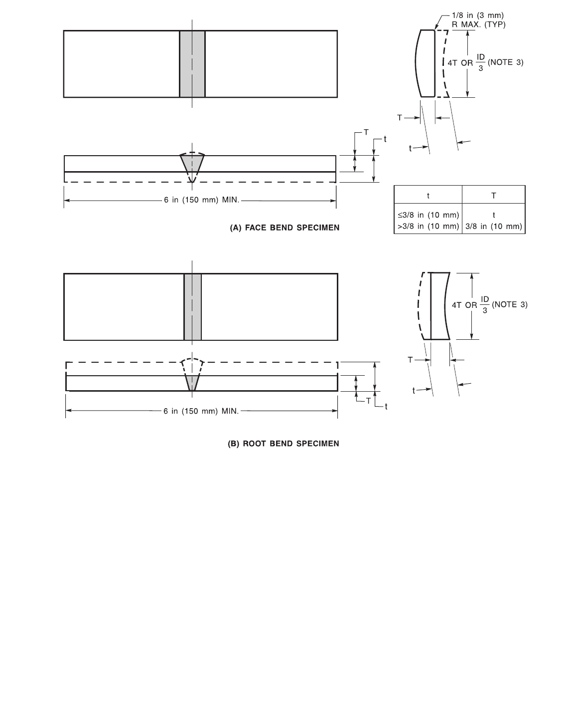
1. The specimen edges may be thermally cut but, in this case, at least 1/8 in (3 mm) of material shall be mechanically removed from the
thermally cut surfaces.
2. If the weld joins base metals of different thicknesses, the specimen should be reduced to a constant thickness based on the thinner
base metal.
3. The specimen width shall be 4T, except that it shall not exceed ID/3 where ID is the inside diameter of the pipe.
4. The weld reinforcement and backing, if any, shall be mechanically removed flush with the specimen surface. If the back of the joint
is recessed, this surface of the specimen may be removed to a depth not exceeding the recess. For performance qualification, if
sufficient material is available, acceptable undercut should be removed while maintaining specimen dimensions.
5. The diameter of the test plunger should be equal to or exceed the weld width. If this requirement cannot be met, a greater thickness,
T, may be chosen in accordance with the formula in 6.6.4.
6. All longitudinal surfaces shall be no rougher than 125 microinches (3 micrometers) R
a
. It is recommended that the lay of the surface
roughness be oriented parallel to the longitudinal axis of the specimen.
Figure 6.6—Transverse Face Bend and Root Bend Specimens (Pipe)
Copyright American Welding Society
Provided by IHS under license with AWS
Not for Resale
No reproduction or networking permitted without license from IHS
--`,,```,,,,````-`-`,,`,,`,`,,`---