Barzam A.B. Automation in Electrical Power Systems (Системная автоматика)
Подождите немного. Документ загружается.

_]
I
AUTOMATIC
FREQUENCY
CONTROL
I1t:
0)L77
(542\
_
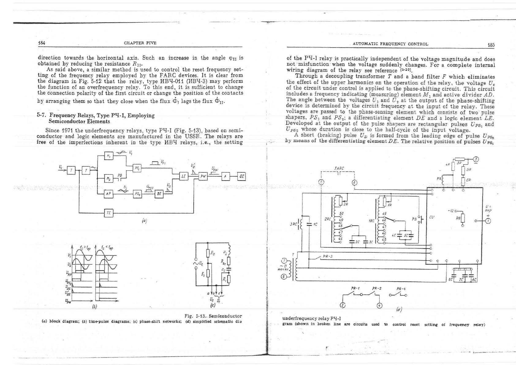
At
a frequenc],
equai
to
the preassigned
setting value
of operating
frequency
the reactance
is
'
r1r:
rcet: osetlll
6-43)
Using tbe variable
resistor.R2,,
set the resistance
of circuit
II so
that,
9ri: 9r
(5-44)
183
The inductive
reactance
of
circuit
I
is
qJaLr-+
(b4o)
^
(')LI
At
a
frequency
equal
to
the
preassigned
setting
value
(or
:
oleer)
the
iuduo-
tive
reactance fi1
has a
definite
value
rr:
Eset: 6)"etLr-
^ + F-4I)
'
@cell-
I
-Since.R1
is
constant,
the
angie
between
tha
current
11
and the
,to\Lage
[J-,
will
change with
a
change
in the
frequency.
Wheu the
frequency
decreases
as
eompared
n'ith
the
operating setting
frequency,
tbe
reactance 11
and
tbe
angle
91
decrease
and
vice
versa.
The
inductive reactance
of circuit Ii
is
fron
Yf
ol
busbar
a
system I
6
-
from
llT
'
ol
husbar
5
systenE
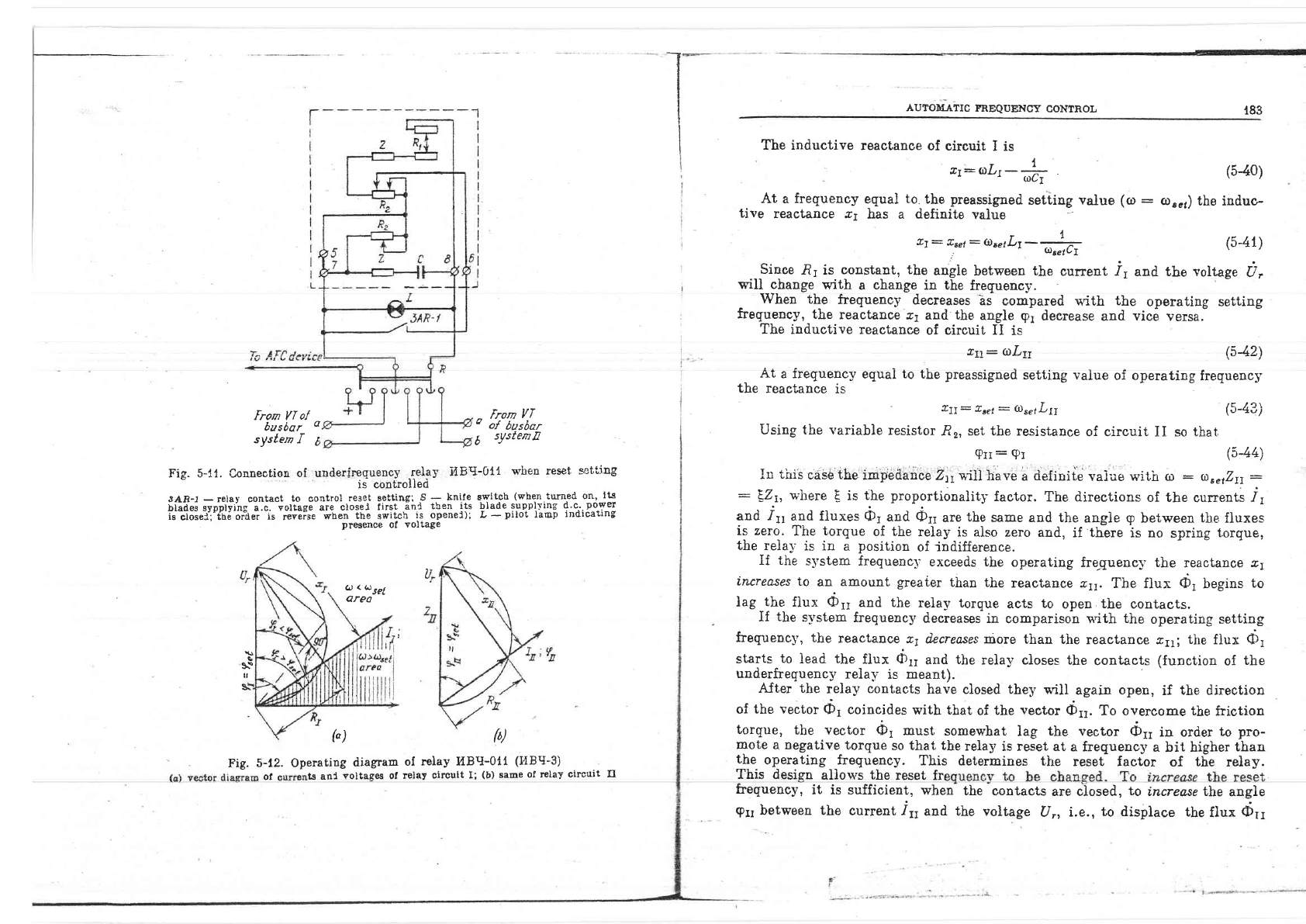
sAn-I
-
relsy contact
to
control
reset
setting;
,S
-
knife
blades sypplyrng
a.c. voltage
are
closel
first
ani
tben
its
is
ctoset:'tn6
orier
is
reveise
when
the
switch
is
openel);
presence
ol voltage
Fig. 5-L1.
Connestion
of underfrequencv
relav
14B9-0U'
when reset
seti'iag
rs conirolled
-
Iu
tiris
case'the
impedaaCe
ZlyviJ|have
a
defiuiie
vaiue
with
ro
:
o)aetZrr:
:
EZt,
where
E
is
the
proportionality
factor.
The directions
of the
currents
-f1
and
.f11
and
fiuxes
tb1
and 611
are
the
same
and the
angie
p
between
the
fluxes
is zero.
The
torque
of
the
relay
is aiso zero
and,
if
there
is no
spring
torque,
the reia-v
is
in
a
position
of indifference.
It the
-s1'stem
frequencl'
exceeds the
operating
frecuenc;' the
reactance c1
increases
to
an
amount greaier
than the
reactance c11.
The flux 01
begins
to
Iag-the
fiux o11
and the
reiay
torque
acts
to
open
tbe
contacts.
If
tlie
system
frequency
decreases
in
comparison n'ith
the
operating settirl.g
freguency, the
reactance
t7
dccreoses niore
than
the
reactance c1i;
the
flux
(D1
starts
to
lead
the
flux dr11
and
the
rela1, closes the
contacts
(function
of
the
underfrequency
rela_v
is
meant)
After the
relay
contacts
have closed they
will
again
opon,
if
the direotion
of
the vector
CD1
coincides
with that
of
the
veotor
Orr.
To overcome the
friction
torque,
the vector
6,
must
somewhat
lag
the
vector
iilr,
io order
to
pro-
mote
a negative torque
so that the
relay
is reset
at a
frequency
a
bit
higher
than
the
operating frequency.
This
determines the
reset
factor
of
the
relay.
This desisn
aliows
the
reset fr
frequency,
it is
sufficient, when
the
contacts
are closed,
to
increase the
angle
switcb
(when
turned
on,
lts
blade
supplf
ing d.c.
Power
L
-
pilot
lamp
indicating
$
\\
tl
6
< uset
Qrea
(") (b)
Operating
diagram
of
relay I'IBrI-011
(I'IBrI-3)
Fig.
5-12.
of
ts anl
voltages of
lelay
circuit I;
(b)
same
of relay
circuit fI
g11
between the
current 111
and the
voltage
U,,
i.e.,
to d.isplace
the
flux
O11
184
CIIAPTER FTVE
direction
towards
the
horizontal axis.
Such an increase
in
the angie
grr
is
obtained
b_v reducing
the
resistance
.Ri1.
As
said above,
a
similar
method
is used
to
controi
tbe
reset
frequeDc5,
se1-
ting
of
the
frequency
relay
employed
b-v
the FARC
devices.
It
is ciear from
the
diagram
in
Fig.5-12 that the
relay,
t1'pe
tr4Bg-0{t
(I4BII-3)
may
perform
the
function
of an overfrequenc]
relaS'.
To this end, it is sufficient
to ehange
the
eonnection
polarity
of
the first
circuit
or
cbange
the
position
of
the
contacts
by arranging
them
so
that they
close when
the
flux O, ]tgt
the flux
(b11.
5-7.
Frequeney
Relays,
Typ"
Pq-I,
Employing
Semieonductor
Elements
Since
197{
the
underfrequency
rela-vs,
t-vpe PTI-I
(Fig.
5-13),
based
on
semi-
conductor
and
logic elements
are manufactured
in the
USSR.
The
relays are
free
of
the
imperfections
inherent in
the
t-vpe
I{B-{ reiays, i.e.,
the
seti,ing
of the PrI-I
relay
is
practicaliS'
io6*nendent
of
the
voltage
magnitude
and
does
not'misfunction
Thgn
the
voltage
suddenl-v
changes.
For a
complete
internal
wiring
diagram
of
the
relay
see
reference
t5-r01.
Through
a decoupling transformer
f
aud a
band filter ^F
n'hich
eJiminates
uJ seqlo
ur
!.rft'
Lrrrlrirtil'rr/lcl
rJ.l.rlB
rirBrlrt,uLJJ.D.
IIIe
I'elaLIrgg poslLIOn
oI
pursgs
upgl
AU?OMATIC
FREQUENCT
CONTROL
Il,
Uprz
^.
' r-_
lP -J.Ps-L---
PR-I
PR.z
Fig.
5-13.- Semiconductor
(d)
simplified schenatlc
dia
urderfrequency
relay PtI-i
gfam (shown
ln
broken
line are
cireuits used to
controj reset
sctting oI
lrequency
relay)
(a)
bloch
dlagram;
(b)
tirnepulse diagrams;
(c)
phase-shift
networks;
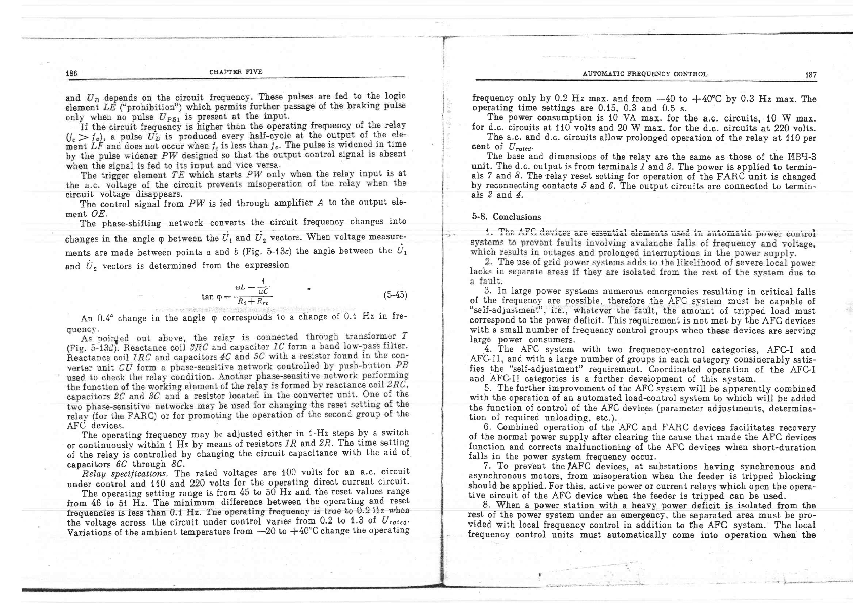
186
circuit
voltage
disappears.
The
contril sign;.f
from
PW
is fed
through
ampiifier
.4
to the output
ele-
ment
OE.
'Ihe
phase-shifting
network
converts
the circuit
frequency
changes
into
chasges
in the angle
g
betv,een
tbe IJ1and. i,
vectors.
When voltaEe
Ineasure-
ments
are made between
points a and
b
(Fig.
5-t3c)
the angie between
the
U1
and
U,
vectors
is
determined
from
the expression
I
r,ilL
-'a
(l)L
tan o:
-;-:---
'
ttli
f,rc
AUTOM,A.TIC
FREQUENCY
CONTROL
frequency
only
by 0.2
Hz max.
and from
-40
to
+40"c
by
0.3
Hz max.
The
operating time
settings
are 0.{5, 0.3
and
0.5 s.
-
The
power
consumption
is 10
VA max.
for the
a.c.
circuits,
10
W
max.
Ior
d.c.
circuits at
110
volts
and
20
W
max.
for the
d.c.
sircuits at 220
volts.
The a.c.
and
d.c, circuits
allow
prolonged
operatiou
of
the
relay
at 110
per
cent of
Uroted.
The base
and
dimensions
of
the
relay
are
the
same
as
those
of
the
I,IBri-3
unit.
The
d.c. output
is from
terminals
-Z
and 3.
The
power
is
applied to termin-
als 7 and
8.
Thetelay
reset
setting for
operation
of
1ne
f'AnC
unit
is changed
by reconnecting
contacts 5
and 6.
The output
circuits
are
cotrDected
to termin-
als
2
and 4.
t-t;
tfrtiT:":^-.,
^^^^-+i^, ^,^*^-+^..^^r :- ^..4^*^+: --a--,
3.
In large
power
systems
numerous
emergenoies
resulting
in
critical
falis
of
the
frequencl.'
are
possibie,
therefore
the
AFC
systein rnust
be
capable
of
"self-adjus'cmeit",
i.e:, whatever
'rhe'fault,
i,he
amount, of
tripped
load
must
correspond
to the
power
deficit. This
requirement
is
not
met
by
the
AFC
devices
with a
smali
number
of frequency
control
groups
when these devices
are
serving
Iarge
power
consumers.
4.
The
AFC
system with two
frequency-control
categories,
AFGI
and
AFC-II,
and
v'ith
a large number
of
group-"
in
each
categor5,'-considerably
satis-
fies
the
"self-adjustment"
requirement.
Coordinated
operation of
the
AFGI
aad AFGIi
categories
is
a
further development
of
this
system.
5. The
further
improvement
of
the
AFC system n'i1l
be
apparently
combined
v'ith the
operation
of an automated
load-controi system to
which
rn'ill
be
added
the
function
of control of the AFC
devices
(parameter
adjustments,
determina-
tion
of
required
unloadipg, etc.).
6.
Combined
operation
of the AFC and FARC
devices facilitates recovery
of the
normal
power
supply after
clearing
the
cause that made
the
AFC devices
function
and
corrects
malfunctioning
of
the AFC
devices
when
short-duration
falls
in
the
power
system frequency
occur.
CITAPTER
FIVE
187
(5-45)
An 0.4'change
in
the
angle
g
corresponds
to
a change
of 0.1
Hz
in
fre-
AFC
devices.
The
operating frequency
may be
adjlsted
either
in
l-Hz strPs
by
a
switch
or
continuously
witnii
I
Hz by
means
of
resistors
/fi
and
Zft.
The
time setting
of
the relay
is
controlled
by
ibanging
the
circuit
capacitance
with
the
aid
of
capacitors
6C
through
8C.
-
Relay
specifLcatio-ns. The
rated
voltages are
100
volts
for an
a.c. circuit
under
ointiol and
110
and 220
volts
for
the
operating
direct
current
circuit-
The
operating settiug
range
is
from
45
to
50 Hz
and
the reset
values
range
from
46
io
51,
Ii.z.
The-minihum
difference
between
the
operating
and
reset
ngquenclgs
Is lgss
f,nan u.'I
n-L,
Lil€
uPurauruB
II|,quEuuJ
rD
urus
u'
the'voltage aeross
the circuit under
control
varies
from
0-2
to
Variationi
of
the ambient
temperature
from
-20
to
+40'C
change
7. To
prev'ent
the
IAFC
devices,
at substations
having
synchrouous
and
asynchronous
motors,
from
misoperation
when
the feeder
is
tripped
blocking
should
be
applied.
For this,
active
power
or current
relays
which opeD
the
opera-
tive
circuit
of
the
AFC
device when
the
feeder
is
tripped
can be
used.
8. When
a
power
station
with
a heavy
power
deficit
is
isolated
from
the
rest
of
the
power
system
under an emergency, the
separated
area must
be
pro-
vided
rn'ith
lcca1 frequency
control
in
addition to the
AFC
system.
The
local
frequency
control
units
must
automatically
come
into
operation
when
the
1.3
of Uroted.
the
operating
188
CHAPTEfr
FIVE
Chapter
Eir
AUTOMATIC
CONTROL
OF
FREQUENCY.
REAL POWER
Af\rD
POWER
FTOWS
nV
POWER
SYSTEIIfS
5-9.
Review
Questions
1. What
is
the purpose
of automatic
freguency control?
\4Ih]'
are AFC
devices consider-
:9
":_ipfortalt
elements
in
power
automatic
control
s]'stems'to prevenr-i"riii
;if;;tfig
the
entrre
systeml
2. What
are the
advantages
and
disadvantages
of
the
AFC
system
*'ith
a
great
number
of
fregu_en-cv control
gror:ps?
-
3.
lVhat
afe the
nurno-.e and valrres of the f.imo sptfinoc rrcai hrr rho AFtl-T ond iFt.-TT
devices?
.
4.
Draw
a
diagram
of
an AFC
device n-ith
blocking
from an active-power
relar- respond-
ing
t_o tb_e.real
Pos'er
floq'in
tbe
Jeeder. 11'hat
shoutd
5e
the
operating
iettine
oi ihis ieiav?
5. What
are
the
purpose
and settings
of tbe
FARC
devices?
6. Desmibe
the
operat.ing principle.of
the.HBtl-3
(IIBTI-011)
induction
frequencv
relal'.
7.
Describe
the
operating pririciples
anci cbaracieristics
of tbe
pt-f
semico'nductir
IrequencS
relay.
8. How
are
the
operating
and reset
frequenc5'
settings
of the
tr{Brl-4 and
prl-I
rela1,s
adiusted?
--'-'i
-'
-
--'-''
9.
lVhat
is tbe
purpose
of tLre additional
{in
a
local area)
freguenct'
control
and tbe
automatic
sectionalizing
controls
responding
to
frequency?
10. What are
tbe. causes
of
.possi'ble
opiration
oi tbe'frequency
relays
of
AFC
devices
in
the
case
of
loss
of s1'nchroniim
in a p6u.,er
system?
11. Name the
causes
of
sbort-time-decreasis
in the
power
slstem
frequenc-r-
where
a
spinning
power
reserve
is
avaiiable.
6-1.
General
^^.Y*,.:.1"-"1,9:f:!r,h-1g,
the,current
frequency
in power
systems
musr
be
vvss^4qvu'>rvY
Du'sLaruEu
at
a value
oI
5U
-+-
[J.t
H'z.
Short-time
operation
at
^ c-^---
I
"r
'iro""at
ln this
case,
the
d"i"ff?rili.J#l
rous
electric
clock
time
should
not
be
r
specified
value,
tbe
dispatcher
of
the
lerating
power
system
must
bring
the
f the
load
frequency
continues
to'
tal]
rsted,
the
Cispatcher
aust
ensure
rees_
ions
b--v
}imiting
or
tripping
some
loads
regulating
instructioni
[er-,
6-2J.
rirements
for
the power
suppll'
quality
]auses
a
labour
productivit5,
reduction
wered
freguency
(belou,
4g.E
Hz
during
IU
Tin)
is
econonlica!.ly
so
unattractive
t
I6-3i.
rows
that
the
use
of automatic
ioad_
bhe
amplitude
of the
frequency
varia-
Lions,
however,
do
not
exeeed
the
iimits
in the
absence
of coutroi.
ns
having
generated
po\iler
reserves
the
frequency
kept
at
the specified
value)
e4v
gvou
evv,r,,Lrrruar
roau
arrocaf,ron
;;il";il
ilii.
inlilri{J'iir"i"Jiirti:
In the
conditions
of
integrated
nowcr
qwqf
oyno rlro ^^-*t^+^ -*J ^-^-^-:-^r
Tt-1Y*::1.:r_Jh,9
generated
power
at the
siations'ro*.ti*5r
it*ii"asible
due
to
insufficient
transmission
capaeity
betweeu
and
in
the
links
ffif"i;
Tt;
systems'
Under
such
conditioni
th;
;;in
p"tiorc
of
the
automatic conrrol
t
190
CIIAPTER
SIX
devices
is
to
ensure
the maximum
Iinks
as
c&n
be
permitted
bv
the
practicable
steady-state
power
transmission
over
those
stability
requirenents.
AU?OMATIC
CONTROL
OF FREQUENCY,
REAL POqIER,
POWER
IILO\F
191
k)
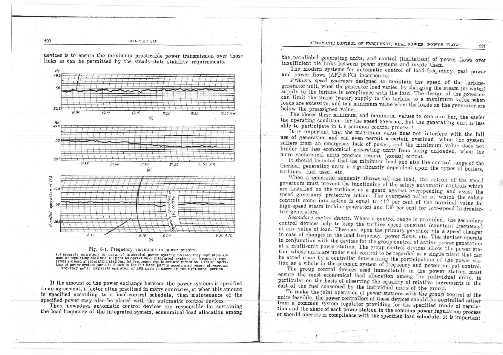
Fig. 6-1.
Freguenc-v varjations
in power
system
{o),separate,
operation. of
parts
of..integrsted
poller
s}-rtem;
no
freguenc}
regrulators
are
utedatre€rulatingstations;
(b)parallel
.operationof
integrated'gystemi
no ireqiencl.
regu-
lators
are
used
at regulating.stalions;
.(c)._frequencl'
regulbtors
are turn6d on.:pirallei ope*ra-
tion
of
powet
system
parts
is
shown
in
tlie
ieft-hand
bart
of acce)erated
recorti cf recoidine
frequencl
meter.
Separate operation of
IPS
parts
ii
shos'n
in the
rigbt-band
portion
-
If
the
amount of
the
power
exchange
between the power
systens is
specified
in
an agreement, a factor
often
practised
in
many
couniries,
or
when
this
amount
is specified
according to
a
load-control
schedule,
then
mainteuance
of
the
Thus,
nowadays
automatic
control
devices
are responsible for
sustaining
the
loael
frequency
of the
int.egrated
system,
economicai
load allocation
among
'
The
closer these
minimum
and
maximum
values
to
one
another,
the
easier
the
operating
condition,
for
the
speed
gov-ernor,
but the
gen;;tt"g
unit
is
less
able
to
participate
in
t.
e common
coniroi process.
,
,.^^Ilrtt_l:l^o:-!Tt that
the
maximum
vaiue
does
not
interlere
wirh
the
fuIl
l::.t-t
HtrucraLruu
aus
can
even permlt
a
certain
overload,
when
the
svstem
Hz
19.5
50
Hz
49.5
54.5
:{,
s
s
\
a,
s
e,
\
b
L
s
A.
2t.55
P.n
rrom
a
common
system.
regulator
providing
for
the
speeified
*oar
oil;g"];:
tion
and the
share
of
each
p-ower
staiion
in tf,e
common
pQwe-r
regulatiop
process
or should
operate
in
compliance
with
tne
specifi"a
io"a
i"n"aui"i
ii'i,
io,portant
AI.]TOIIATIC
CONTROL
OF FREQUENCY,
REAI, POT{rER,
PO]FEN
FLOTfl
193
CEAPTER
SD(
that the
schedule
be corrected
as
to the
frequenc-v
and real
power
flow over the
tie
lines.
In
the
so-cailed decentralized
control
systems
the
group
control
devices of
individual stations
used
an astronomical
time
clock
as
the
central
regulator.
Such
a referenee
clook had
to
be
instalied at each
power
station
to
provide
exact
time
indication
within
a 24-hour
period
to
*0.05
s.
System
control dnuices act upon
the station
generators through the
group
control
systems and control
the
ioad foeguency, real
power
and
power
flows
in the
power system
and
its
parts.
With
a
centralized
AFP
&
FC
system,
the
control
pulses
acting
upon
the
station
controllers are
produced
by
the
central
regulator.
The required input
information
and
mode
of regulation are
preset,
the controllers
of
the group
control
devices of
the
individuai
power
stations being
acted upon by remote
control.
In
practice,
this
type
of centralized
regulation
'was
used
in small
power
poo!.s
worki.g
in
isolation from
the
integrated
power system
or was
used
as
a
means
of
centralized
control of a
group
of
power
plants
from
the load dispat-
chiug
departm.ent of
the
power
s1'stem.
Witil
the
decentraiized AFP&FC
s-vstem,
the
controi
signals acting
upon
the
generating
units vrere
to
be
executed by
devices
installed
onl-r' 31
the
re-
gulating
power
stations
without using
remote
controi.
However,
the
necessit-v
to
correct
the
output of
certain
power
stations
v'ith
the
aid of
the
power
fiows
on
the transnission lines made it
impossihle
to
givu
up
remote
eontrol
and'in
fact
caused an increase in
the
nunaber of
the
remote
control
channeis.
Due
to
integration of
the
power
systems
the
decentraiized
regulation
method
turned
out
to
be unfeasible as
it
was
n.ecessary
to
limit'the
action
of
the
group
control
devices
with regard
to power
flows
in
the
tie
lines
and
to
take
into
account
the
losses in
the
transmission lines,
aII of
which
needs
a fairl-v
Iarge
amount
of remote
control
equipment.
Tire
group
control
devices
installed
in
some
of
the
power
stations
for decentralized
regulation
have
proved
useful
in
accomplishing
power
flow limitations
on
tie ]ias5
t6-al.
\ryith the mixed
AFP
&
FC system
used
in
the
integrated
power
systems
of
the USSR
economical load
allocation among
the
generating
units
is
obtained
b1'using
a
preplanned
schedule
prepared
in each
power
system
b-v
group
control
station
controllers.
Practice
shows
that
unplanned
departures
from
the
pro-
periy
designed load schedules
do not
exceed 2-3
per
cent.
The
variations cause
changes
in
the volume
of
planned pos'er
flows
over
the tie
Iines
and
in_the
power
s-vstem
frequency. Correction
of
the
above-mentioned
parameters is
placed
witb
tLe
central-regulator
acting
upotr a certain
number
of
the
power
stations
u'hich
deai
with unplanned ioads.
In-a
number of cases
the task of handling
unpianned
Ioads
is
assigned
to
one bydroelectric
power station
possessing the needed
geueration reserve.
Simultaneously
this station
perform the
load-frequency
regulation
function.
The central regulator
must consider
the
power
exchange
@
the tieiirrks trctwuen-aower
where
P
:
power
output
of
the regtlating
(pilot)
po\
;er
station
Po,:
planned
power
of
a
power
station
(optimum
when
there
is no
de-
parture
from
the
planned
value)
Lf
:
frequeney
departure' from
the
preassig:red
(rated) value
LPtt: pou,er
flow
departure
from
the
planned
value
X
and
'C
:
iegulation
fact'ors determining
the
share
of
the
regulating
statiou
in
ihe
control of unplanned
}oad changes.
The
factors
are
selected
so
tliat
optimum regulation
is achieved
When
several
power
stations handie
the
unplanned
load
variations
their
group
control
s-vstbms are activated
from a central
regulat'or
installed
at
the
load control
centre. The
participation
of
each
power
station
is
determined
by
patcher
cannot directll'
control
the
settings
of
the
corresponding
apparatus,
functions
simiiar
to the above must
be
performed
by
the station
operators
according
to the
directions
of
the
power
system
dispatcher
or
independently
making
the
necessary conections
against
instrument
readings.
power
system control a
iimited
number
of
pon'er stations.
-
When accomplishing
such
a
system
of mixed regulation
tire
central
regulator
of
the integrated
power
system may
act
upon
the regulating
power statioos
through
the
regulators
of
individual
parts
of
the
power
system
rather
than
directly.
6-2. Freguency
and Power Regulators
Thc
primary
regulator of
thc load-frequcruy
and real
power or,
in other
words,
4L^ ^--^ J -^--^-- ----4--^ --:+L^--+ -.L:^L +L^ +-.-]-i*^ -n-^rnf ar
i,ge speeo governor
is
a
proeess
apparaius
wif,ilout
'w$.Ic.ir
LIle
i,ururDe-geneiai,{rr
unit
cannot
work
undei
conditions of
varying
load.
If the
generating
unit
r3-2076
792
gapls5sisn
[6-5)
tl
P:P-,--l-K, I uat+K,Lf+C, I
aP*dt
,t.
..1
.J
00
+
ctLP
il
(6-1)
overloads.
The
principle
according
to
which a regulating
Ioad
frequency
and
po\per fiow
control
functions
power
station
performs
the
is
given
by
the following
-=.G.-*
,t
o(
t94
CEAPTER
SE
operates
at
a
preassigned
speed
(at
a
preassigned
frequency)
and
under a certain
electrical
load,
tbe
amount
of
steam
(or
water)
supplied
to
the
turbine
cor-
responds
to
this ]oad.
With
a change in
the
electrical
ioad
and no
change
in
the
anount
of
steam
(water)
fed
to the
turbine per
unit
tirng
i15 speed wiII
alter and
the
generating
unit
v'iii
decelerate
if the
electrical
]oad
increases
or
accelerate
if
the
electrical load
deereases.
To
automaticaliy
reestabiish
the
initial
speed, the
steam
(water)
florv
to
the
turbine
and
the
electrical ioad
must be
brought into
agreement. This is
AUTOMATIC
CONTROL
OF FREQUENCY,
REA],
PO
TER,
POIFER
FLOW
The
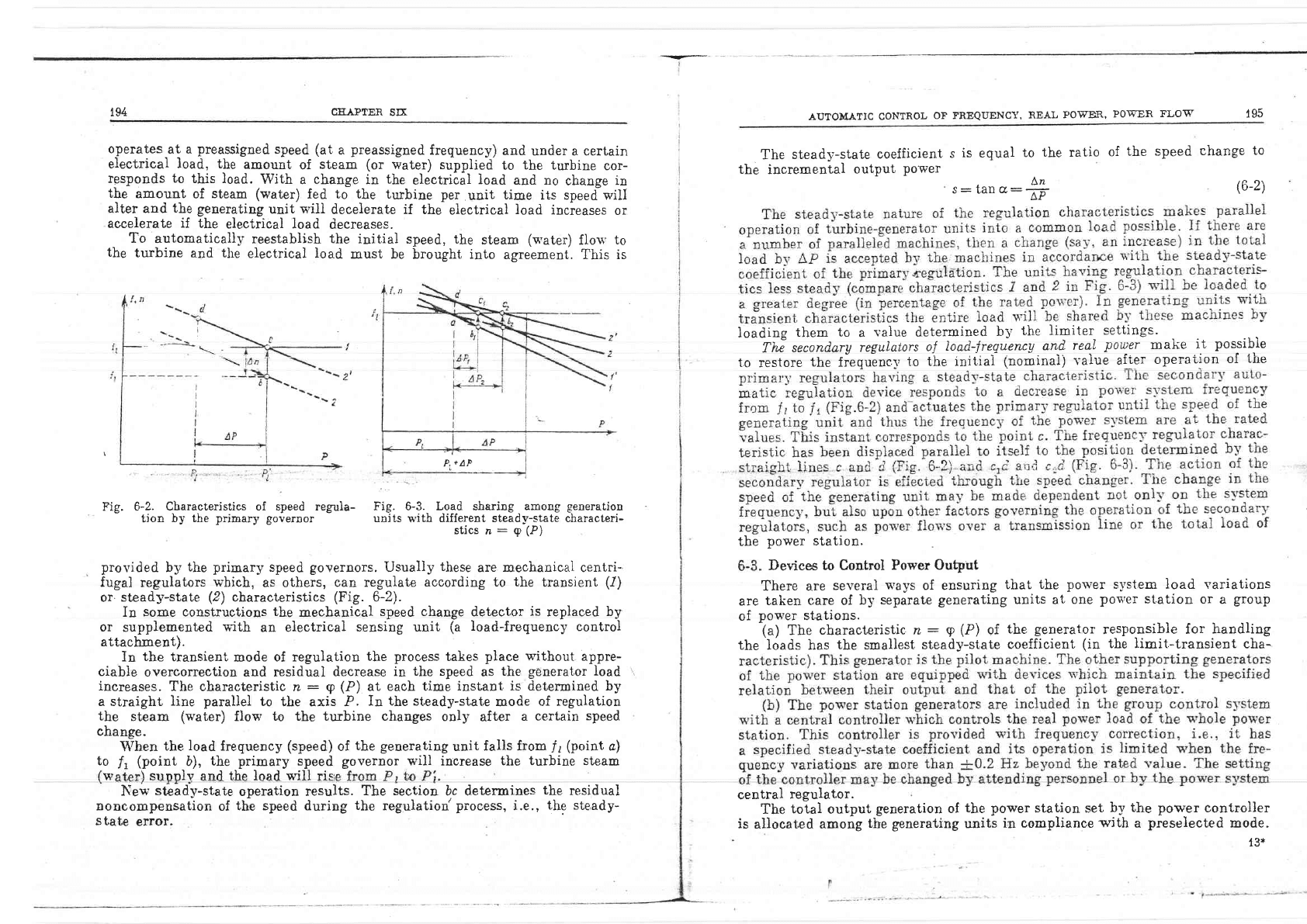
steady-state
coefficient
s
is
equal
to
the ratio
of
the speed
change
to
the
incremental
output
Power
An
s:
tan
o:TF
loading
them
to
a
value
determined
by
the
limiter
settings.
Tli
secondary
regulators
ol
load"-frtqirn
y
and
real
pow_er
make
it
possibie
to
restore
the
fiequencl,
to the rnitiai
(nominai)
vaiue arler
operai,ion
oi
tiie
the
power
station
(6-2)
-l
P,+AP
Fig. 6-2.
Characteristics of speed regtla-
Fig. 6-3. Load sharing among
generation
tion
by the
prinary governor
unjts
with
different steady-state characteri-
sticsn:q(P)
provided
by
the
primary
speed
governors.
Usualiy
these
are mechanica] centri-
fugal
regulators
which,
as others,
can regulate
according to
the
transient
(1)
or.
steady-state
(2)
characteristics
(Fig.
6-2).
In
some constructions
the
mechanical
speed change
detector
is
replaced
by
or
supplemented
with
an
electrical
sensing unit
(a load-frequency
control
attachment).
In
the
transient
mode
of regulation
the
process
takes
place without
appre-
ciable
overcorrection and residual
decrease
in
the speed
as
the
generator load
increases.
The characteristic
n
:
g
(P)
at each
time
instant. is determined by
a straight
line
paraliel
to
the axis P.
In the steady-state
mode
of regulation
the
steam
(water)
flovr
to the turbine changes
only
after
a
certain
speed
change.
Devices to Control
Power Output
There
are
se\zeral
ways
of ensuring
that
the por*'er s.vstem load variations
are
taken
care of
by
separate
generating units at
one
power
station
or
a
group
of
pou'er
stations.
(a)
The
characteristic z
:
p (P)
of
the
generator
responsible
for
handling
the loads has
the
smallest
stead3r-state
coefficient.
(in
the
limit-transient
cha-
to
When
the
l,
(point
load
frequency
(speed)
\F
sunnl
b),
the primary speed
v and the load will ris
of
the generating
unit
falls from
lr
(point
a)
governor will increase
the turbine steam
The
section,
bc determines
the
residual
the
reguiation'process, i.e.,
the steady-
Ner*'
steady-state
noncompensation
of
state
error.
operation results.
.L- ^--^l -l---:--
Lu€ sPecu
uufrug
central
regulator
The
toiai
output
generation
of
is
allocated among
the generating
the
power
station
set
by ihe power
controller
units
in compliance
with
a
preselected
mode.
13*
-.-I-_
19i
r96
GAPrER
SS
ALTTOMATIC
CONTNOL OF FREQUENCT,
RF-AI
POWffi.,
POFSR FLO]ii
case of
faults
in
the
remote-control
channels
or when
a
posrer
station
with
its
area is separated.
In
the
apparatus put
into service, provision
is
made
for
devices
s'hich
allov'the load
settings
to be
changed
manuali-v. Use
i*"
also
made
of
instruments
indicating
the
load
assignment sent to the
stations.
(c)
Distribution
of
the loads
among
the generating
units
of
a
power
station
and among the power stations
taking part
in the
freguency
and power
regula-
v'on
is
according
to the
increme-ntal
characteristics
u'ithout
communication bet-
tieen
the power
station
group
controller
and the
central
regulator
effected
With.generating
units of
the
same
t-vpe,
for
example, tbe
load
is
uniformly
sbared
hl'tU
the
nachines.
When the-machines
are
of
distinct tvDes. theloai
is
so
divided that
in
terms
of reference
fuel
the
relative
incremenial
iuel
con-
of the
integrated power
system
as a
!"
t'"tt*J
singie whole
in
rel.ition to
its partici-
;i\
-
pation
in the
common
regulation
sy-
r{47
l.-
:. -
!ir,eul .
To
stalion2
Tbe
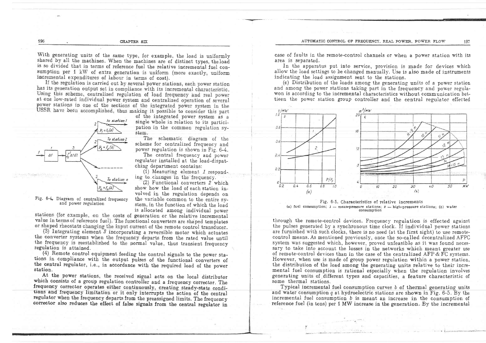
schematic
diagram
of
the
_]X-
scheme
for centralized
frequencl'
and
e=/r(0/
\
po\,l'er
regulation
is
shoq'n
in
fig.
6-4.
The
central
frequencl'
and.
power
regulator
instaLled
at
the load-dispat-
ching
department
contains:
(1)
h{easuring
element
-I
respond-
To
stqtion,
itg,!9
gnanggs
il the
frequenc-r.
<.-
(2)
Functional
converters
2 which
show
hou' the load
of each station
in-
volved
in the
regulation
depends
on
Fig.
6-4.
Diagram
of centralized
frequenc-v
the
variable
common
to the
entire sv-
and
power
regulation
stem,
in
the
function
of
u,hich
the load
0-2
0.4
0.6 0.
E t.0
a
ft)
ta
20
J0
+0
50
ntw
/t,.\
is
allocated
among individual
power
generation
or
the
relative
incremental
rctional
converters
are
shaped
templates
;unent
of
the
remote
control transducer.
ting
a
reversible
motor
q'hich
actuates
ncy
departs
from the
rated value
until
rormal
value,
thus
transient
frequency
reguiation
is
attained.
(o)
,ue,
""*,-o,ll,1
,T
ii$13-'Ji:'l::;1,1'1"1";"1-'r'i""f;:',1",,o*,
(b)
!,.ater
consumption
through
the
remote-control
devices.
Frequenc5-
regulation
is
effected
against
the pulses
generated
b5'
a
s1'nchtorrous
time clock.
If individual
pou'er
stations
are
furnished
u"ith
such
clocks, there
is
no
need
(at,
the
first
sight) to
use
remote-
control
means.
As mentioned
previously,
once
the
so-calied
decentralized
AFPC
system v'as
suggested
which,
hou'ever,
proved
unfeasible as
it
q'as
found
neces-
sarl'
1o take into
accouut the losses
in
the
networks
r+'hich
meant greater
use
of remote-contro]
devices than
in
the
case of
the
centralized AFP & FC
s1'stems.
Hou'ever,
when
use
is
made of
group power
regulation
within
a
power
station,
the
distribution
of
the load
among
the
generating
units
relative
to
their
incre-
mental
fuel
consumption
is rational
especially when the regulatio.n involves
generating
units
of
-different
t5rpes and
capacities,
a
feature characteristic of
some
thermal
stations.
,rfnw
(4)
Remote-control
equip.ment
feeding the
control signals
to
the
power
sta-
tions
in
c-ompliance
with
the
output
pulses
of
tbe
fu"nctional
converters
of
the.central
reguiator,
i.e.,
in
accoidanie
with
the
required load
of
the
p**t
station.
. .A-t
the
power
stations,
the
received
signal
acts
on the iocal
distributor
which
consists
of
a
group
regulation
controlier
and
a
frequency
corrector.
The
frequency
coffector
operates
either
contiuuouslv,
creatin-E
steadv-sta
f,rons
aDd
rreguency
ltmitation
or
it
only
interrupts
the
action
of the
central
regulator
wlen
the
freguenc5'departs
frcm the preaisigned
limits.
The frequeucy
and
s'ater
consumption
g
at hydroelectric stations
are shos'n
in
incremental
fuel
consumption
b
is
meant
an increase
in
the
reference
fuel
(in
tons)
per
1
MW
increase
in
the
generation.
By
Typical incremental
fuel consumption
curves
b of
thermal
eneratins units
ig.
6-5. Bl
t
consumption
of
the incremental
corrector
also
reduces
the
etteci
of false
signals
froi the
centrd
r;fiilt*
ii
j
,;:-"
-:
''
?6-
.--r*-_
198
CEAPIER
SD(
AUTOMATTC
CONTROL
OF
FREQLTENCy,
REAL
POWER, POWER FLO\V
199
wate.r
cotrsumption
g
is
understood
an increase
in the
water
supply
(in
cu.m)
per
1- s'
when
the
generation
is
raised
by
{
I\{W.
\Vith
the
hydroJl'eciric
genera-
tors
b
is
assumed
to
equai
i.g,
where
?,-is
a
conversion
factor
to
be
used in
re-
computation
of
the
characteristics.
It
is
seen
from the
characteristics
shown in
Fig.
6-5 that
an increase
in the
-steqm
.su.pply
to
the turbine,
or
u'ater
to
the hyd'roturbioe
carrses
an increase
in.
fuel (water)
consumption.
Tire incremental
consumption
transducer
takes
this
regularity
into
accouni,.
The
foilowing principle
"iartti*iilr
t."o.ducer
operation.
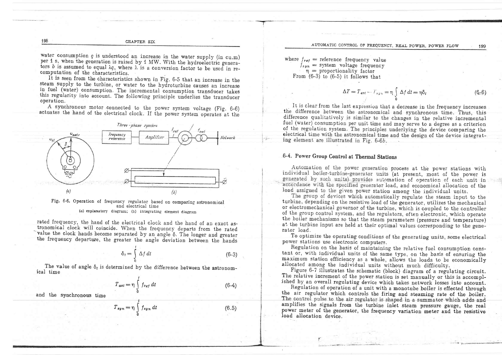
A synchronous
motor
connected.
to_ thl
power
system
voltage
(Fig.
6-6)
actuates
the
hand
of
the
electrical
clock.
If
ihe
power
svstem
operates
at
the
v
I
(,)
(6)
Fig.
6-6.
Operation
oI
frequency regulator
based
on comparing
astronomical
(a)
expranaro,r
ai"L"jo:tiil":fJ"J#ti,,
u,.-.,,,
diasram
rated
frequencl',
the
hand
of
the
electrical
clock
and
the
hand
of an
exact
as-
tronomical
clock
wiil
coineide.
\Vhen the
frequency
departs
from the
rated
--value
the
clock
hands become
separated
by
an- angle
"0.
fir.
Ionger
aoa
great"r
the
frequency
departlue,
the
greater
the
-angie
d'eviation
betw-een
the-hands
t
6,:
I
Mdt
6
The
value
of angle
61
is
determined
by the
difference
between
the
ical
time
?asr:
I
l,t
dt
It is
c,learfrom
the
last
expiession that
a decrease
in
the freguene5,
increases
the
difference
between
the
astronomical
and
synchronous
time.
Thrr.,
this
difference qualitativel-v
is
similar
to the
changes
in
tbe
relative incremental
fuel.(water)
consumption
per
unit time
and
maiserve
to
a
degree
as a criterion
of
the
regulation
lystem.
The principles
undeilying
the
device
comparing
the
electrical
time with
the
astronomicaliime
and
the
d-esisn of
the
devic! intu-srat-
ing
element
are iliustrated
in Fis,.
6-6ii
-
- o
6-4.
Poq'er
Group
Control
at
Thermal
Stations
In process
at the
power
siations
with
ts
(at
present,
most
of
the
power
is
or.ration
of
operation
of
each rinit
in
'Ioad,
and economical allocation
of
the
;:,fiT".:E"l*"'ifi'l*:*
H;:?
ro
the
turbine,
depending
on
the
resistive
load
of
the genirator,
utilizes
the
mechanical
or eiectromechanical
governor
of
'the
turbine,
i'hi"n
is
coupled
to the
controller
oj
t{te
group
control
system,
and
the
regulators,
ofien
e}ectronic.
which
operate
the
boiler
mechanisms
so
that
the
steam
parameters
(pressure
and
temperature)
a*,
the
turbine
input
are
held
at
their
optimai
values
iortesponding to ihe
gene-
rator load.
To
optirnize the
operating
conditions
of
the
generating
units,
some
electrical
polpr
stations
use electronic
computers.
Regulation
on
the
basis
of maintaining
the
relative
fuel
consumption
cons-
tant
or,
v'itii
individual
units
of
the
same
type,
on
the
basis of
ensuring
the
maximum
station
efficiency-as-a whole,
allows
the
loads
to
be
economiially
allocated
lm_o+g
the
individual
units without
much
difficulty.
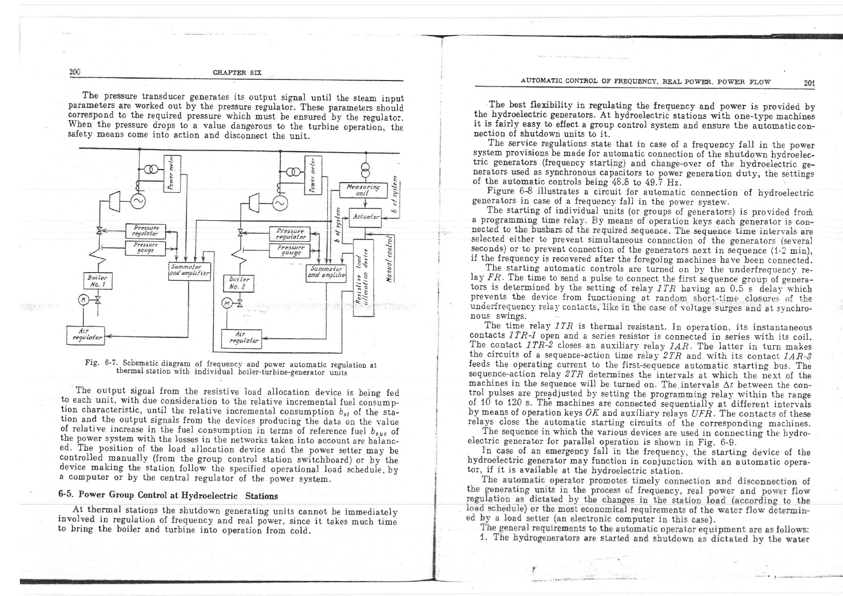
Figure
6-7
iilustrates
the
schematic
(biocki
diagram
of
a
regulating circuit.
The
relative
increment
oJ
the
power
station
is
set
ilanually
or"this is
?ccompl-
ishd
by
an overall
regulating-device
u'hich
takes
network
losses
into
account-
Regulation
of
operatjon
of a
gnit
with
a monotube
boiler
is
effected through
where
lret
:
referense
freguenc-v
value
l ry,
:
system
voltage
freguency
q
:
proportionality
factor
From
(6-3)
to
(6-5)
it
foliows
that
L,T
:
Tort
--
/
r!t,,
:tr
I
At d.t
:
q61
,.|
t0
(0
6)
r
J
0
(6-3)
astronom-
(64)
aottr
and the
synchronous
time
T,cn:n!
f,r^at
the
air
regula-tor
which
controls
the
firing
and
steaming
rate
of
the
boilJr.
rrr1.^
^__r_^l _
.l-
, rl
.
r
/6 5)
amplifies
the
signals
from
the
turbine
inilt
rt""*
pressure
Power -ngeter
of the generator,
the
frequency
variation
meter
load
allocation
device.
gauge,
the
real
and
the
resistive
CEAPTER
SB.
The
pressure
transducer_
generates
its
outpu!
signal
until the
steam
input
paraEeters
are
worked
out
by the pressure
regulatoi.
These
parameters
shouid
ge-rrespo_nd
to the
required
pressure
which
must
be eusured
-by
the
regulator.
When
the pressure
drops to
a value
dangerous
to
the turbine
operation,
the
safety
means
come
into
action
and
disconnect
the
unit.
AUTOM.A.TIC
CONTROL OT
FNEQUENCY,
REAI
POWER,
POWER FLOW
2Al
Fig'
6-7..
Schematic.diagrap
of
_freguencl'
and
pou'er
automatic
re6jriation
at
tlrermai
station
*-ith
individual
boiler-turbine-generator
unlts
The
output
signal
from the
resistive load
allocation
device
is
being
fed
to
each unit,
with
due
consideration
to the
relative
incremental
fuel .oor"u-p-
tion
characteristic,
until the
relative incremental
consumption
b*'
of
the
sta-
tion
and
the
output
signais
from
tire
devices
producing
the
data on the
lalue
of
reiative
increase
in
the
fuel
consumption
in
terms
6f reference
fuel br;
;i
the
pou'er
system
s'ith
the losses
in
the
netw'orks taken
into
account
are
balanc-
ed.
The
position
of
the load
allocation
device
ancl the poriler
setter
may
be
controlled
manuallv (from
!\q
groqp
control
station
srvitchboard)
or Uy tfre
device
making
.the
station
folldw
the
specified
operational load
sched;i.,;y
a
computer
or by the
central
regulator
of
the power
system.
6-5.
Power Group
Control
at
Hydroelectric
Stations
The best fle.xibility
in
regtlating
the
frequency
and
power
is
provided
by
the hydroelectric generators.
At bydroelectric
stations with
one-tfre
machinei
it
is
fairiY
Qasy
to
eflect a
group
control
system
and ensure
the
auiomatiocon-
nection of shutdos'n
units
to
it.
The
service
regulations
state
that in
case
of a
freguency faii
in
the
power
system
provisions
be
made
for
automatic connection
of
the shutdown
hydrbelec-
tric
generators
(frequency
starting)
and
change-over
of
the
hydroelettric
ge-
nerators
used
as
s5mchronous^
capaci_tors
to
power
generation
duty,
the
settiigs
of
the
automatic
controls
being
48.8 to 49.7
Hz.
Figure
6-8 illustrates
a circuit
for automatic
connection
of
hydroelectric
generators
in
case
of a
frequencv
fall
in
the power
systeri'.
The starting
of individual
units
(or
groupi
of
generators)
is
provided.
frorii
a
programmiqg
time
rela5'.
By
means
of
operation
keys
each
generator
is con-
nonf o.l fa 1|'n l"'ol'^-. ^f +l^^ -^--.i-^l ^^---^-^-
tTrL
- -- - -, - - L:,, ! r
svvwu sv
uus
!Bo!€1rr
\rr
ul.rv
rEuLuteu
DUquuuue.
rllg sgqugll{/g Lrmg
In.Ler\.ars
are
selected
ei'r,her
'r,o
preven'r,
simuitaneoui
connect,ion
of
the
generator-s (severai
99c9nd,s)
or to
prevent
connection
of
the generators
next
in slquence
(1-2
min),
if
the
frequency
is
recovered
after
the
foregoing
machines
have been connect.ed.
. ltr
starting
automatic controls
are
turnei
oo b5' the
underfreguencv
re-
Ia}'Fft.
The
time_to
send
a
pulse to
connect
the
first
seouence sroup'of
genera-
tois
is
determined
b-v
the
setting
of relal'
7?n
h;;t;;;;b.5=:."-f"i".:;[i;
prevents
the
device
from
functioning
at random
sholi.--tirne
closurei
,if tl:e
underfrequenc])
ieial'coni,acts,
like
in
the
case
of voltage
surges
anri
at,
s-vncirro-
DOUS SWrngS.
The time
relay
1?R is
thermal
resistant.
In
opeiation.
its instantaneous
contacts
lTR-I
open
and
a
series
resistor
is
conneited
in series rvith
its
coil.
The
contacl
ITR-? cioses
an
auxiiiarS'rela5,
IAR. The
latter
in turn
makes
the
circuits
of
a
sequence-action
i,ime
relay-2TR
and
q'ith
its contact
lAR-3
feed-. the
operating current to
the
first-seguence
aufomatic starting
bus.
The
sequence-action
relay ZTR
determines
the
intervals
at
which
the
next of
the
machines
in the
seguence
wili
be
turned
on.
The
intervals
At
bet*'een
the
con-
trol
pulse.s^ge
Pj_egdiusted
b-v setting
the programming
re1a5's'ithin
tbe
range
of
10 to
120
s. Thb
machines
are
connected
sEquentialiy
at d.ifferent int,ervais
by
means
of operation
keys
OK
and auxiliary
reir-vs
UFR.
The contacts
of
tirese
relays
close
the
automatic starting
circuiis
of
the
corresponding
maclr.ines.
_
The
sequence
in
u'hich
the
various
devices
are
used
in connectin!
the
h-,*dro-
electric
generator
for parailei
operation is shou,n
in
Fig. 6-9.
In
case of
an
emergency
fall in the
frequenc-v,
the
starting device
of
the
hydroelectric
generator
ma1' function
in conjunction
p-ith
an a[tomatic
opera-
tor,
if
it
is
available
at
the
hydroelectric
station.
F
\
*o
\
o
.s
\
\
\
s
:\
s*
ES
.$t
?t:
\i
At
thermal
stations
the
shutdo*'n
generating
units
cannot be
immediately
invalved
i;t
regu)ation
of
frequency
aid
real
po*er,
since
it talies
much time
to
bring
the
boiler
and turbine
into
operation
fron
cold.