Barzam A.B. Automation in Electrical Power Systems (Системная автоматика)
Подождите немного. Документ загружается.

=.....-F--
CEAPTEN
SEVEN
R.{PID
PARALLELING
OF
SYNCFR
ONOU.q
G
ENERATORS ool
rr or7 ^:_
2tl"ptpo6
U
6n:
/U
c
Sln
--T-
where
U":
value
of the
voitages
being synchronized
l,
p
:
permissible-specified
difference
of
the
frequencies
of
the voltages
being synchronized
t'iead:
tims 1.-ie_ad
the
optinum point
which
is equal
to ihe
own clos-ri.r-e
+;-^ ^f +L^ --,.:+^L
!I49
L,l
tllrt
Dh.lL,tJlt
The
frequency
at wbich
the
FCR relay
drops
out
its arnature
(control
of
the
ctrop-out
trequeuc-v)
is
controlied
by chauging
the
vaiues
of
resistors
J9
and 24
Lo
27.
tfe-
capacitance
of
eapacitor
L6
and
the val.ue
of
resistor
40
connected.
in
paraliel
with
the
coil
of reia1,
T arc seiected
so tbat the
decrease of
the
magDetic
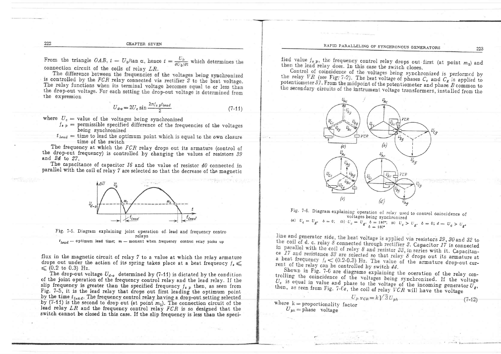
Fig.
?-5.
Diagram expiaining
joint
o_peration
of
lead
and frequency
contro
relays
tlead-
optimum
lead
time;
m
-
moment
s'hen
trequenc1. control
rela-r'
piclis
up
flux
in the
magnetic
circuit
of
relay
7 to a
tahle
at
which the
relay armature
dropj^out under-
the
action
of its spring takes
place
at a beat
frequency
l,
(
<
(0.2
to
0.3)
Hz.
'elay
drops-out..first
(at
point
mr)
and
ue
swrl,ch
closes-
ie-s
being
s1-nchronized
j-s
performcd
bv
oltage
of phases
C.
and
Cr'is
applied
tb
re
potent.iometer
and
pirase
.B
common
to
voltage
transformers,
instaljed
from the
(7-1
1
)
un,
/l
3r/
rLK
a\
(,
un,
9
,)
$,-)--
---'
"ry
I
\t/
\i-/
(')
fI
,A,
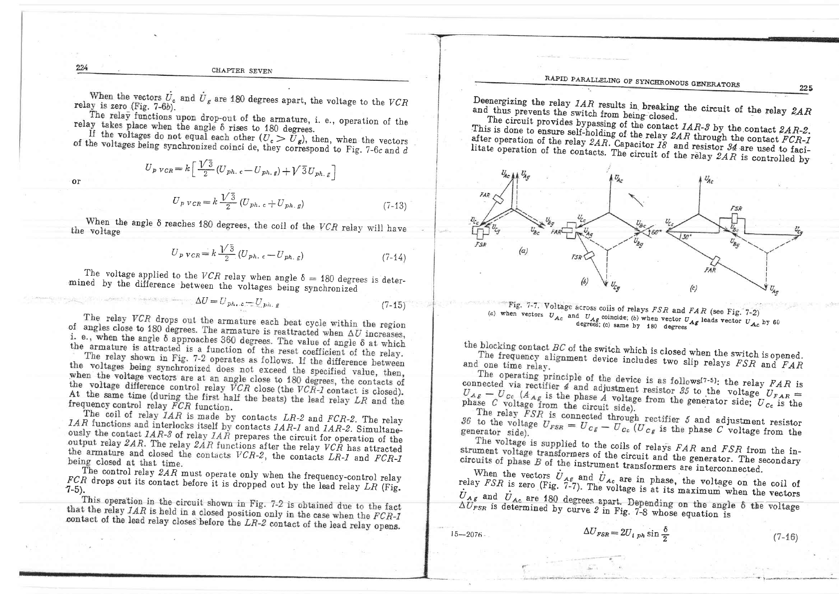
Fig.
7-6.
Diagram
e-rpiaining
operation
(o)
u":
us,
6:
o;
",::jtiT.r:i"j
ur-
aA"c
oI rclar-used
s1'ncb
ron
ized
18C"; (c)
U^
>
1 8C.
to
control
coincidence
of
L,g,
d:0;
C-
U")
Ugt
via
resistors
29,30
and
Jl
Lo
9.
Capacitor
l7
is
connected
in
series
rn'ith
it.
Capacitan-
8
drops
out
its
armiture
at
the
armature
drop-out
cur-
Fig.- 7-5,
it
is the Iead
relay
that
drops
out
first
leadinf tne
optimum
poinf
by the time
lr..r.
The frequencv
control
relav havins a drJn-out sitting selbcted
ec
r-\
urJUar
ln
\:alue
and phase
to
tbe
voltage
of
the,,incoming
generaLot[ig,
then,
as
seen
from
Fig.
i-d,1he
""ri'"i,.rrl,ticn
s,iil
iia'e
th? iortage
- Th"
drop-out
voltage
U6-o
determined
by
(7-11)
is
dictated
by the condition
oj
th,e
joint
operation
of
the
frequency
contlol relay
and the
leid relay. If the
lljn
fle_queney
is
greater
thau
the
specified
frequenc5'
l,
p
then,
as
seen from
!y
(Z-ff)
is_the
second to
drop
out
(at
point
rnr).
The connection
circuit
of
the
lea.d relay.L.R
and
the
fuequbncy
contlol
relay
FCR is
so
designed that t.]re
shou'r
in
Fie'
i-6
are-di;;ili;#"iri"e
itre
ooeration
of
the
relay
con-
trolling
the
coincicjence
of
tEa.'ollages
heing Srnehrnnirpd Tf rho i!^l{^,^
Lrurrrrrg
rne
corncldence
of
the
vol.t,ages
h.eing
s1'nchronized.
If
tt.
i;"iirg,
,t;'".tt
jj:.:]-tl:t*:
"n-d,phTe
to.tt
E-oo.rffi
oi'
rrr"
incoming generator
u".
oh.rg,
Ji
:
proportionaiitl.
factor
u
ptt:
phase
voltage
-switch
cannot
be
closed
iu this
case.
If the
slip irequency
is less
tlan
the
speci-
CHAPTER
SEVE}i
RAPID
PARALI,ELING
OF
ST,I{CERONOUS
GENERA"ORS
0
degrees
apart,
the
voltage
to
the
VCR
of
the
armature,
i.
e.,
operation
of
the
es to
180
degrees.
tfe.r
({.
}
U
g),
then,
when
the
vectors
:i
de,
they
coriespond
to
Fig.
7_6c
al.d-i
rr , f V3
U
p
vcl:
fr
L
ff
(U
nn.
,-
(J
ph.
,)
+{5U
ro.
,1
OI
225
U
n
rrr:
k
VTt
(U
on.
,
*U
pn.
s)
ar
Whg.o
the
angle
d
reaches
lg0
degrees,
the
coil
of the
LIre
volEage
U
p
vcn:
n
l/r3
(U
pn.
,
-U
pn.
s)
L,U
:
{,i
7,h,.c-,,Li_pn.
e
.
T!"
voltage
applied
to
the
VCR
relav
when
anele
6
:
Ig0 deor
nained
i,l'
tfiE-aifurr*.r-n;];;r;
the
vorrag".
rrlo?t;;tt;f;iles
is
deter-
*;lf:':Tl",.ll?"":lT 14{
resulrs
in
breaking
the
circuir
of
the
relay
ZAR
* urlo^T",
I::,l"lI _th,"
rT;i
t.h
i;;lffi
;":iH#:
Ilj
;"T,,"11
:l:nt
":.
Llf:tji3g :ilt].ii :qliift .r3 a-
r
b{
th
e
c
on
ra
ct
z
A R
_
z
.
Thi;l;;;ffi
rJ'uvrues
Dvpassms
of
t_he
conract
144-3
by
the
conract
2AR_2.
arrer
operarion
"i?H:j":T;.Ti*r""::lg.i4x
U4
t;e,idn
in,
""J,
b,ct
FCR_I
ffffi
'ffi
iiilil":Jg
j,:*'*#"q+1"i:i.i;it'"'S:ifr'#ffi
ffi i'['i:;{
ritate
operation
or ;d
"",it"'i..'fh:Til#ir'ir
lfri
trt'#t?:#
l;""H:l"li"iT;
p-sp
rs
determined
by
cu*ve
e
in
fig.
7-8
whose
equation
re
voltage
(7
-13)
VCR rol^r; u'ill I"^-'^
,!
rrr
uq
YE
(i
-14)
(i-15)
contacts
LR-Z
and
FC.R_p.
The
relav
contacts
IAR-I
and
IAR_Z.
Simultane-
prepares
the-circuit
for
operation
of the
tion-s
after
the
rela_v
IzCfi
has
attracted
I/CR-Z,
the
conraits
LR_t
and
FCR-_I
Tbe
control
relay
zAR
must
oqgr.ate-
only
whel
th"
freq-uency-contror
rera5,
{:rf
drops
out
its
iontacr
before
it
is
a"opi"a
out
by the
i;;;-;."i;y
rft
(Fig.
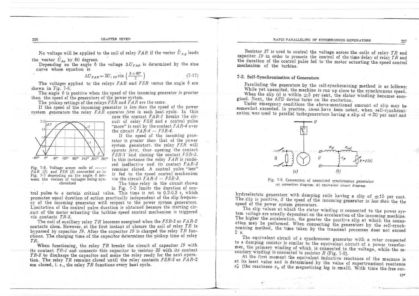
-"1F.-^,:1
V_o-ltige
1.._"-r.
coiis
of
reiays
p.'.R
and
f.A.R
(see
iie.
t_2,)
wnen
Yectors
u
a."
""t"ru#,i:l':*";
,i|1;i".-:H""*iL!,
"*r"r
rirr
by
60
:;," -"{r
i.s
zero
(Fig-
f:zi.Tn,"firi"gr'i,
#i?:'Jfi;"#ffh:l
,'ff;:iL::
U
nt
and
Ut"
At@
180 rlcorooc on6h+ r-\^-- ,.
i
the
svritch
which
is
closed-when
the
sq,itch
isopened..
enr
device
include-q
two
,Iit;i;i*"p'.?
;;;ifllft
,s's[7-5].
tbe
relay
FAR
is
to
.the
voltage-
flre,n:
lene.rator
side;
U".-
ii-
the
'
-and
adjustment
resistor
phase
C
voltage
from
the
i
to
the.coils
of
relays
lAR
and
.F,S,R
from
the
in_
rers
of
the
circuit
and
*r;;;;toi-iir"
secondary
instrument
transformers
are
interconnected.
.
WL.l
the
vectors
IJ
oo
and.
i
relayj
rsn"i.
#o
(Fio
z-zr
.n"^tj:,ll!
F-
pf".:",
the.voltage
on
the
coil
of
|
5-207t1
Afl
qr7
6
ert-zFs.R
-
LU
t
ph
Srn
t
226
CHAPTER
SEVEN
No
voltag.e
wiII
be
appiied to
the
coi] of
relay
FAR if
the
vector
L;3,
ieads
tbe
vector
IJ
o,
by
60 degrees.
Depending
on
the
angle
6 the
r,oltage AfJro^
is determined b5
the
sine
cunie
whose eguatian is
LUFA.R:
2(r,rn l"
(3=q
)
f
7-r7)
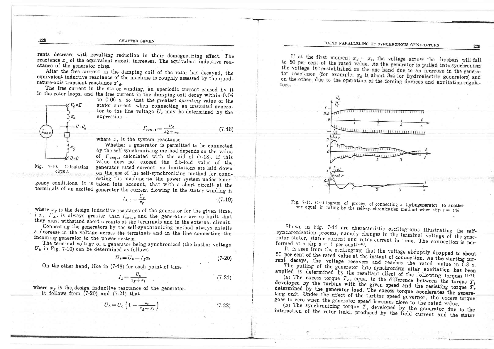
The
voltages
appiied t.o the
relays
FAR
and FSfi
\'ersus
the angle
6 are
shown
in
Fie. 7-8.
The
angle 0
is
positive
u,hen
the speed
of
the
incoming
generator is
greater
than the
speed
of
the
generators
of
the
power s-vstem.
The
pickup
settings
of
the reiays
FSfi
and FAR
are
the same.
If
the
speed
of
tlie incoming
generator is
iess tltan
the
speed ol
the
po$'er
s-vstem
generators
the
relal
FAR operates
/irsl
in
each beat
cycie.
In
this
ca-.e
the contact
FAR-L
breaks
tiie
cir-
cuit of relal'
^FS.R and
a
controi
pulse
"more"
is sent
bi'
the
contact
FAR-4
oter
the
circuit
FAR-4
-
FSR4.
If
the
speed
of
the
incoming
gene-
rator
is
greater
than.
that
of
tire
po\^'er
system
generators. the
relal'
.F-SR
ll'ill
operate
f-irsi.,
thus
opening
*.he
coni,aci
,FS.R-l'
'and
closing
the
corrtacL
FSR-3.
In
thi-"
instance
tire
relay
FAR
is
rende-
red
ineffectii'e
and
its contact
FAR-3
remains closed.
A
control
pulse
''less"
is fed
to the
speed control
mechani-"m
via the
circuit
FAR-3
-
FSR-3.
The
time relay
in
the
circuit
shorvn
in Fig.
7-2
iimits
the duration
of
con-
trol
pulse to
a certain
critical
value.
This
time is
set
to
0.2-0.3
-",
u'hich
promotes
equal duration
of
action
practically independent
of
tire slip frequen-
c1,
of
the
incoming
eenerator
rn'ith respect
to
the
power s-r'stem
generators.
Limitation
of
the
control
puise
duration
is
obtained
because
the
starting cir-
cuit
of
the
motor
actuating
tlie
turbine
speed control
mechanism
is
triggered
lia contacLs TR-?.
The coit
of
auxiliarl-rela5'
f.R
becomes energized
when
the
FSr?-2
or
FAR-Z
eontacts
close.
Ho$'ever,
at
the
first
instant
of
closure
the
coil
of rela-v
IR is
b1'passed b5 capaeil,or
19.
After
the
capacit.or
J9 is charged
the
reial'
?ft
fun-
ctions.
The
charging
time
of
the
capacitor
determines
the
pickup
time of relay
-600
00
60"
120"
tE?"
240"
3000
56Co
Fig.
?-8. Voltage across coils of
)
(
i,, \
:
FAR
(1\
and
F,SJ?
(2)
connected
as
jt,
Fig.
7-7 depentiing on
the angle
6
bet-
*'een
the
l'ector-c
of
voltages
being st,n-
,
chronized
RAPID
PARALLELING
OF
SYNCIIRONOUS
GEh,ERATORS
227
'
Resistor
37 is
used to
control
the voltag€
across
the
eoils
of rela1,
1"R and
cSpacitor
19
in
order
to
promo-te
the contr6l
of
the
tine
delaj
oireia5,
l -R
and
the
duration
of the
contrbl pulse
fed to
the
motor
rctu"ting
in"
.p"ea
cootrol
mechanism
of
the
turbine.
7-3.
Self-S1:nehronization
of Generators
Iaralieling
the
generators
by
the
self-synchronizing
method.
is
as
follows:
\4hile
yet
unexcited,
the
malhine
is
run
up
clo*"e
to"the
-*yo.h.ooous
speed.
.
Yh:f
the
slip
(Q_i.
within
:tB
per
cenr,
it,e
si"to"
":irai"J
Uecornes
ener_
gized.
Next,
the
AFD
device turns
on
the
excitation.
Under emergencl'
conditions
the
above-mentioned
amount
of
siip
may
be
somev'hat
exceeded'
In
_practice,
cases
have
been
noted,
when
self-s;nchiooi-
z-ation
s,'as
used
*n nrrollot rrr?l'^geiiei'ators
having
a siip
oi+20-per
eeni
anri
{'r-
il
fl I
IJJ
(')
ft.)
Fig.
z-9.
connection
of unexcited
svnchronous
aenerator
(a)
connectjon
diagram;
(b)
eguivalent
circuit
diagram
h-vdroelectric
generators
with
damling
coiis
ha'ing
a
slip
of
tl5
per
cent.
The
slip
is
positive,
if
the
speed
of thE
incomint
generator
is less
than
Lhe
Lhe
speej-
of
the
po\^'er
system
generators.
The
slip values
at
u'hich the
stator
winding
is
connected
to
the
power
svs-
tem
voltage
are
usuali-v
dependent
on
the
r..ei&"tion
of the
incoming
machine.
Tbe
higher
tbe
acceleiation,
tlie
greater
tiru-positile
slip
at-wnrcii
the
conne-
ctio.n.
may
be
p-erformed-
When
ionnecting
tl. generatbrs
b_v the
self-synch-
ronizing
method,
tbe
time
taken
b]'the
iransi.;i
p;;."*""=-'Ao.r
not
exceed
2s.
n=f(s)
TR.
When
functioning,
the
relay fft
breaks
the
eircuit
of capacitor
/9
with
TR-z
to
discharge
the
capacitor
and
make
the
relay ready
for
the
next
o
pera-
FAR-2
tion.
The
relay
IR
remains closed until
the
reiav contacts
^F,S.R-Z
or
are
closed, i.
e.,
the
relay
I.R
functions
every beat
c-vcle.
.228
CEAPTER
SEVEIi
RAPID
PARALI/ELII{C
OT'
SYNCERONOUS
GENERATON,S
rents
decrease
with
resul.tios
reduction
in
their
demagnetizing
effect.
The
reactance
c.n
of the
equivalent
circuit
increases.
The
equivalent
inductive
rea-
ctance
of
the generator
risqs.
AJter the
free
current
in the
damping
coil
of
the
rotor
has decayed.,
the
equivaient
inductive
reactance
of
the
macLine
is
roughiy
assesssd
by t[e
du"a-
rature-axis
transient
reaotance
r' o
The
free
current
in the
statoi
winding,
an aperiodic
current
caused
by
it
ia
the
rotor loops,
and
the
free_
current
in the
dainping
coil
ciecay
within
0.04
uc=E
U
=Ut,
Fig.
7
-10.
Calculating
ci
rcui
t
gency
conditions.
It
is
terminals
of
an
excited
to
0.06
s, so
that
the
geateit
operating
vaiue
of
the
stator
current,
when
connecting
aD
unezcf,ted.
genera-
tor
to the
iine
voltage
U"
may
be determined
by
the
expression
7'
a"
I
con.
s:
:-?
&d-T
&E
u;ho.o - ic fha
qrrcfam
rnoafo^^^
v'4vtv
&5
tr
vuv
ueruvglg
lgqvuquuE.
Whether
a generator
is
permitted
to
be
connecled
by the
self-synchronizing
method
depends
on the
value
of
f'"on.,
calculated with
the
aid
of
(7-i8).
If this
value
does
not
exceed
the
3.S-fold
value
of the
generator
rated
current,
no limitations
are
laid down
on
the
use
of
the
self-synchronizing
method
for
conn-
ecting the
machine
f,o:the
po**r
iystem
uncier
emer-
taken
into
account,
that with
a
chort
circuit
at
the
generator
the
current
flowing
in
the
stator
winding
is
(7.18)
i:".,
1',..
is alwayi
greater
than 1i^,." aud the
-gene.aio"s
"."
*'loitt in"i
I
r-oey
must
withstaod
short
circuits
at the
iermiDals
aDd itr tbe
extertral
circuit. I
- ,coaneotiog
the
gsrerators
bv
tbe
self-svnchron.lziog
pethod
"t*"j', "riiiti
i --.-91-T?_-T.-Iic.
7-!1
8re
claracreristic
oscillogrs.s
illustrarilg
the
seu-
a
d€ctease
itr the voltage
across
tbe terminals aad
in the
line couuecting
the
I
syl]chrouizstioD
process,
ramely
cbarc-es_iu_rhe
teiltiral-i:Ji"ga'ii
tir"
g"o*
:]"tTi%"T-"fj'ii'll,l\''""}ii.,xlil?Liagsyncbronized1,h"bu.b""uoI'"g"liiJ!1,.i'"1T',iJ;'JL"i1?.#.o.,11ror''curlentintine'Thecoi-e
1,.,:
*
(7.1g)
'e
\"Lvt
I
Fic'
rt
1,:-,of-tlL"-qt:T,-ot.,ptoce!s
ot cohecti'g
r turbogebe'rot
to
atro1ber
where-t,
is the d.esign
inductive
reactatrce oI
the
gelerator
lor tbe
givetr
tim€,
I
one
equal
i! rrtiog
!v t'b'e
t"tt-n,"hio-iiiil]6
;;ffi';;'#:1;p:j1"fi
U5
in Fig.
?-10)
can bi aea.iioea
",
touoi"
"
i un ll"t:.,:f'"rtfl:*:^;::t1,."^q:-r.!tt
rhe.
voltage
abiuptly
dropped
to
about
Ri*8
verDor,
the
excess
torsu
uu:L)"-
tex,
(7-zo')
I
,tgfiff'*,"t
lor:.""1i1,:*":"::l"h"f"'fj"i9iiiil.1;;5:'i."ff:ti:JidTJ:
os t'he
other
hand, like
in
(?-18)
for saoh
point
of time
i
,"#: ttt::il..:,1h^",.
si1"i{1;;'!ig
"l'"coromsm
arter
excitarion
tras
been
r,:.-o--e,-
u.z,)
i
:'":ilihi:.F:i:'i"liiidl.,"",**,1";i*rflJ:i"tliru*rl',1"
*_l?;
developed
bv
the
turbine
-"rth
-tt"
eio;-d;il'ffi"
d:'H:*r,tf;
ff;ff:
fl:
l,:,:'Tii,.orpi:i-o:,.q.i:I^3r;o3a- .ri-:.;;;il."rsue
acceterates
rbe
senera_
d"-ry
rr-i,
th€.desisu
i.nductive
!-eacrance or
th€
sensrator.
,
a*"''ililr,***li:iliii#'i".,!1"ftr'it"J.T'*,i'*
1""";
,ll'"d
.#
It follows lF n
(7-2OI
epd
(?-tl)
rhai
-
i
ting nnft-
Ulder
tb;
eft€et
of
tb;
l;rurle
speed
o it
CIIAPTER
SEVEN
ield.
its
value
is given
by
?r:
&s&
.1o
5
where
E
d
,t:generator
emf
at
, ,r""al,l
rotor
current
t1 ,2\
\
t
-LO)
--^
Id- io
I'7"os:
Uf'-;-:- sin
26
(7-24)
where.ra
and
eq
are the
generator
direcl-axis
and
quadrature-axis
s),-nchro-
nou-c
inductive
reactances.
'
RAPID
PARA],I/ELING
OF
SYIICERONOUS
GENERATORS
231
Tire
reactionary
torque
is proportional
to
the
square
of
the
stator
terminal
voliage
and
'aries
in
time
wi[u
i
coubiec
slip
frequency
A
generator
is puited
in
svnchronisr
at
a
speed
beiow
the
synchrbnous
one
the
stator
u'inding
has
been
connected
to
the generator
speed
and
thus
makes
me-c
comparativel;-
small,
the
excitatior
cnronous
torque
arises
which
pulls
the
srving-s.
In
this
case
the
influence
of
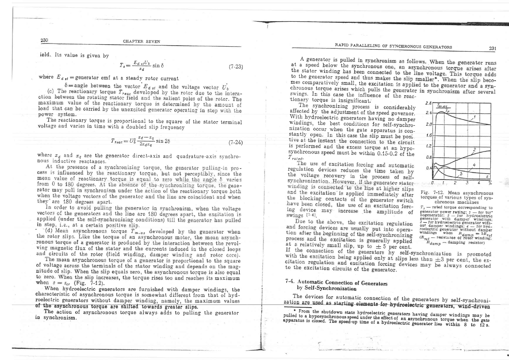
tionurl'
torque
is.
insignificant,
z.
^-
The_
synchronili"f
process
is
considerabil,
*.Ttqa
by
the
adiustment
of
rhe.p""d;;;;;;;;.
2
\Yit!
h1'droelectriC
generators
having
"3
a^-p.,
t*'indings,
the
best
conditions
for
ieif-svodro-
2
nization
occur
*'hen
the
gate
apparatus
is
con_
stantly
.gpe.n.
in
this
casjthe
slip
must
b,
pori
t,
rrrle
ar
lne
instant
t.be
connection
to
the
circuit
is
performed
and-
the
excess
torque
at
an
-h;;_
t.
s5'nchronous
speed
musr
be within
O.f;
O.Z ;f
;h-
.I
rot
ed.
u
s maxrmulll : -,
:
7-4.
+ulo{-ragc
ConnectioD
of
Generaton
Whea
bydroelectric
gensrators
are furoished
wiih dampef wiodi!.gs,
the
i
ly
Se[-Slachronization
characierrstrc
oI asvrchmaous
iorque is
sonewhat
differeot irom tl::;|"\It
i - -l.-g^"vics:
Ior
auromirtic
conneciion
oi.
the
generators
by
serr-synchroni-
0.
i.
?
.l 4
%
The
actioo
of
asvnch.r'ooous
torque always
ad'ds to
putiine
the
seneralor
t
..
r.
FmDo
th6
tbutdown.trt€
by.lro_electric.
g€Dersron
brving
dabper
wiDdilgr
roay
be
io synchroaisn.
!
-
pu'6d
to
e
bvpolrvbcbno'ous
sDesd
urd-€r_tb_s
qtJ;t
"r
"i-i"i"-iiffoiii'riigo"
*o"o
,o"
"rr"
i
-
aplalrtus
is
clo*d.
The
rpeed_up
ume ol
a Dydrool€ctrjc
i€lsmtor
lj€3
qdthib
g
to
12 s,
CEAPTER
SEVEI{
RAPID
PARAUJqLING
OF
SYNCERONOUS
GENE.RATORS
?33
with
a
short
circuit
on
the
busbars
the generators
and the
lines
are
discon-
neoted.
The
ARc
device
connects
the
busiarr-i**
t[..y;;-ria..
If the
generators,
and
engine-powered
generE
starting
devices
from
the
cold
state
are
rating
unit
into
operation
needs
consj
However,
the
deviies
for
automatic
cr
chronization
may
be applied
at
therm
of
a
wa:sned
up
"machiirl
or toeether
v
after
a short-circuit
fault
on th-e
busba
ces are
operative.
A
freguencv-difference
ielav
or
a
speed
relay
i-q
used.
as
the
slip
indicator.
The
circuit
of tue
aetic;
i;;"l"matic
connection
of
penerarors
h' corr-o,,--
given,
the
relay ,S.R
closes
and
hold-s
ting
pulse
'nay
be sliort-time.
The
coijs
are
clo-"ed
by
the
contacts
Sfi-2
and
4
turns
on
the
turbine
starting
devic,e
it.
;ynchronou-"
speed
and the
slip
becomes
ference
reiav
(l
to
i.S
F,.z)
it ;,il]
make
ma-v
be accomplished
in
a pulse_like
a
pulse
pickup
rela1,
pJ?
which
irolds
cont,act
PR-?
breaks the
circuit
of
one
1eiay,
the
coil
being connected
to
the
The
contact
p:R-S
Eloses the
switch.
s
coil
is
deenergized.
iocLing
contaets
BC-Z
and
BC_4
close,
n.
The
contact
BC-I
opens
the
cireuii
reset.
device.
The
contact
BC-4
prepares
the
self-synchronization
device.
The
genera_
!rf,
tors
are
reconnected
one
after
inother
after
the
speed
has
decreased
to
, oulu"
suitable
f
or
self-str'nchronization.
it
shoujd
be
nored that
the tripped
generators
may
be
reconnected
also-by
the
precise
s-vncltronization
method
by
using i,he
ACT4
auiosynchronizer.
con_
L
sidered
in_
the
foregoing
section.
Given
belos'
is
a
typica]
circuit
of
a
-
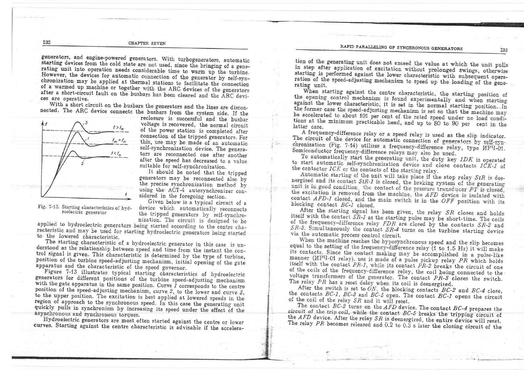
The
starting
characteristic
of a
hydroelectric
generator
in this
case
is
un-
derstood
as
thJrelatijnship
beiween
speed
and time
from
the
instant
the
con-
trol
.signal
is
given.
This
iharacteristii
is
dererminld-;;
rt;
ffi;
of
turbine,
Figure
7-13
jLlustrates
t5rpical
-.tarii"g
-"Eu.u.tiirtim
of hydroelecrric
generators
for
different,
positions
of
the
tirbio"
rp..a-ili"rtid
mechanism
witll
the gate
apparatus
in
the
same.position.
Curv.
j
"or"eriooaiio
the
centre
reclosure
is
successful
and
the
busbar
r \.
voltage
is
recovered,
the
normal
circuit
t
/
tn
nf +ho hnst^, a*a*i^-
.l^
^--- r -r - -r .r
"n
_
of the
power
station
is
completed
after
connection
of
the
tripped
generators.
For
f
={
11
.
- ---rr--
vvru'
^
vl
tm-/n
?hrc llco frqv l-^ *^l^ ^f ^- ^--&--- -a!
s___1
__-v, gev
AqJ
uE
uarrl'
ur alll
duLu[IaLlc
generators
are
aost
often
started
against
the
centre
against
the
centre
characteristic
is
advisabie
if the
or lou,'er
accelera-
Hytiroelectric
curves.
Starting
position
of
the
turbipe
speed-adjusting
mechanis*,
loiii
PL'DrLrur'r
ur
LrIe
rurorne
spee0-adJustrng
mechanism,
initial
opening
of the
gate
apparatus
and
the
eharatteristic
of
t[e
speed
governor.
l^"?*::jj^lh: :l-r.:d-adjusting.r,,echanisp,
*1"" z,-tr"iir,
ffi;; ,od
,ur.,,
.?,
uu
VUIIC,
!1
,
::_:* :pqr_lt""itio.n. .Tire
r*Eit"tioo
is
blsi
"ppri"a
"t
io""r.i'=prra,
in
rhe
*vl'er
PUuururr'
ruu
c^cluaLlolr
rS
DeSl applled
at
IOWefgd
SpeedS
in
the
::fl:l:.:f_:,ql'::'l 19,1h'
-s-vnchronous
speed.
f"
tiri,
";*
;i;;ei'erating
unit
guicklv
pulis
in,synchronism
by increaiinf
itr
rp-"a
""i;;ili"";;frrilir
iir"
tr*i."Ea#i;:i,*;;.*ru8"ruff
#fft::.ff
;*-:,:-"i
The
reiay
p.R
becomes
! 1 - v
'*
iir"
Joriog
circuir
of
the
CH.A.ITER
SEVEN
RAPID
PARALLELING
OF
SYNCERONOUS
GENERATORS
switch
will
open,and
the
ci-osing
circuit
of
coil 1
of
rela;'
FDR
will
oe
prepared.
loading.requirements
and
set
b3, the
p
is
at f
ault,
the
stop
reiay
,St,R
functioui
rator
is tripped
manualiy
with
the
air
contact
2C
K-3)^o1
yher
lhe
output
prr
The]
reiay
Slft
holds
irself
with
thr
rg_c.ircuit.
The
contact
SIR_S
prepares
This
circuit
is
controiied
li
iUe'con_
t
the
opening
pulse
is given
after
the
-apparatu-s
occup_v
the
no-load
pcsition-
riernor
sGtrr
.
rhe
conra
cL
stR-i
*"k.."tf;X?fi:r3trll;"fr:Tir":r*:,tf;S"f;;
starts
to
close
the
gate
.apparat,us
until
op.t"tion
of
the
limit
su,itch
of
tbe
spee4-adjusting
geai
SAG-2.
rFL^
o tn i
ii",:
T
f .ffi
id"i#
?f E'il"Tr,T
:T.
the
sg'itch
is
opened
manua}ll,
bj,
cio
or
g'hen
opened-
bl,
the
proteciion
cont
generator
srvitch
closes
immediatelv
u,i
to
move
to
the
no-]cad
position.
Ajter
the
sn'itch
is
opened,
the
blocking
contact
B!^i
opens
the
.,opening,,
:i::lil.
"t
the
gate
gonirpJ
iriotor
and
th"e
conract
ic-r;i;;;"
rhe
''cl.osing',
tripped
(rhe
AFD-I
contact
bas
been
The
contacts
of the
speed
r-ela1,
,SpR
are placed
into the
circuit
iJ
the
star-
the
frequency-diff
erence
1",'/f;i:;{
devzces
stR
Pout
-2
stn-2
Speed
gyoyernor
molor
JOfr
5P-1
stP-4
sPR
t
!
rrr-,
sAE'z
8C_6
GCfr-/
r-.-.<
Bc
-)
GCn-Z
From
slarting
rclays
tro-tl
rcx-t
I'
s!
|
t
5P- |
sA7'I
l''ore
cc
-B
pT
BC-l
tDN-t
2cx-l
l^
_t
|
|
8c-3
Slorltnc
pulse
PtCttUP
atd.Totu
"r-f
t
r?gyencv-
dt'tfer"icp
Closinq
brea*fr
rl
ir
15K-2
2t
ll
toil II
of
ntazi
FDR
Coil
f
of rfui,
oPtn
rt
Rt
\\
c'\
q'F
\\
a\f
nzsm
o,[
t.tmi ter
BC
-6
ArD.2
-s:!,-!:!!:',=,
-..v
1.
vavq
s.9
o./
stop
relal'
'##+
--
::':-
Aii_J_..-)
ryrnzry
on
etcita.tion
L -
--
---
--
---r>
l''f{f
,'!;1
aDd
regutqt
t
on
from
busbar
yollace
trtnstlorme,7
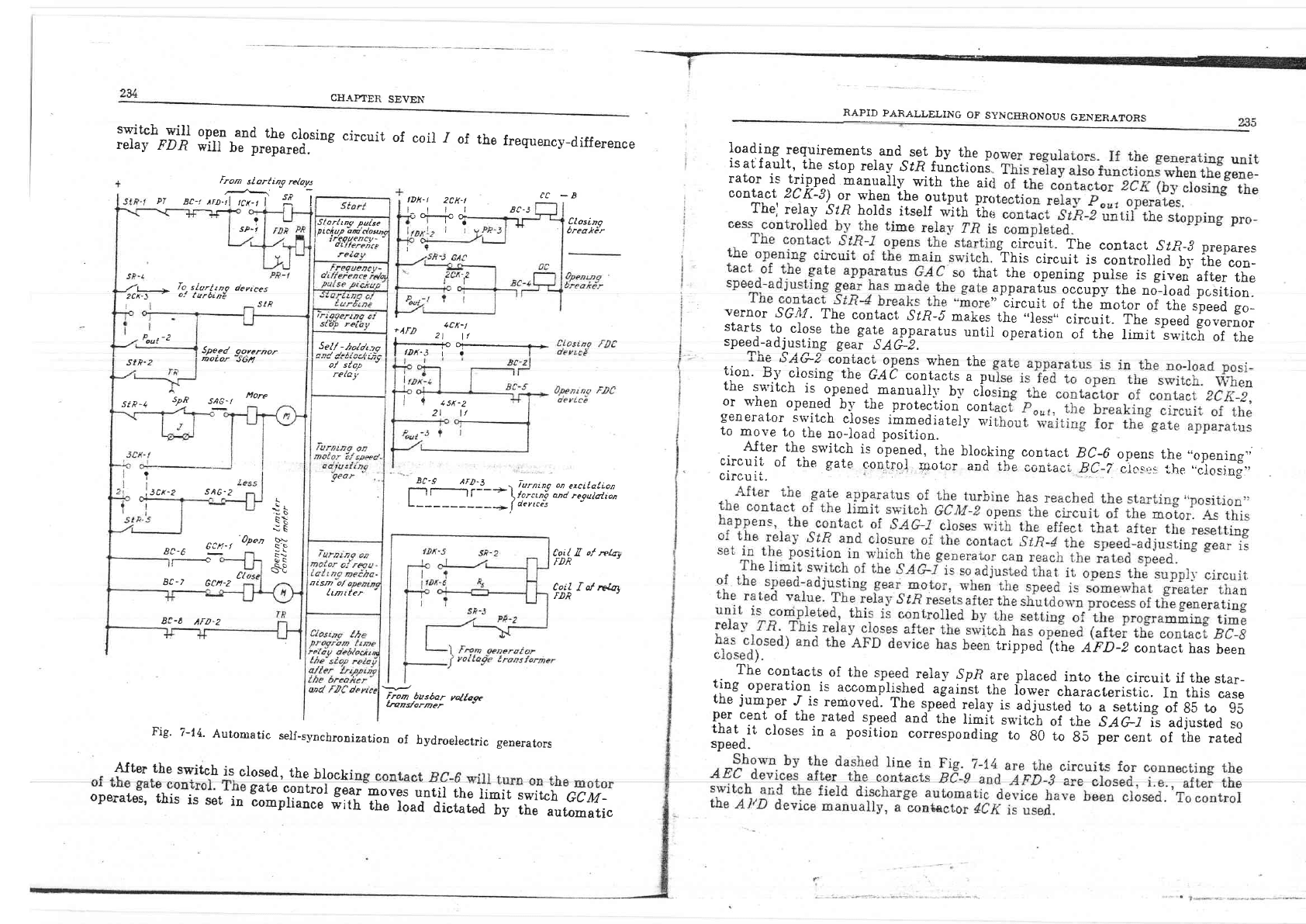
Fig.
7-14.
Automatic
self_synchronizatjon
of
hydroelectric
generators
$Iter
the
switch
is
closed,
the
blocki
ting
rv
s
eug
ouql-
ting.
operation
is
accom-plished
against
the
iower
characleristic.
In
this
case
thg
iUmner./ i.c rornnwod Tha c^o^.t -^1^-.:^ ^r:---r,r r
l:ip:i l:.::::ved.
fhe
.,pgid
Tgr^I
i*
uai"rt.J'
to
* seffiing
of
85
ro
e5
lu'l_"?_ot^*]l:_'1r"9 :tg*d
and
the
iimit
,il;;;;i;h;
s;a;
i'r""aff"d
;;
;;
8;
;;;';'"i"JfJ"ll',7
cha^rl
speed.
gate
controi
gear
compliance
iith
moves
until
the
limit
the
load
dictared
bv
switch
GCM-
the
automatic
operates,
this
is
set
in
CHAPTER
SE\|EN
7-5.
Speed
Control
Methods
With
the
circuits
for
automatic
,
rtian fhp rliffoo.-^o !,a+_.^^- _r-^ao:l:"tion
of
g-enerators
by seU_synchro_
li:i:,"T
"
*l:
^ TIr:l:: l. . I :ll _,.."
ii
.-
r,
;;;
qry
p
l'
fi
*ri'J'ffi
"
#;
#fi:l
:ff"T
fl"Xtit'%'ligt*i
jjo:-i'^:."1"i3":::ilidd;v*;;:.;;"1'ii5niJ""il-Tr"t"-
RAPID
PARALLELING
OF
SYNCERONOUS
GENERATORS
T*lrror""**"ry, *m_l^r":":^rl:li:d
byr.eans
of
eeutrif_ugal
relays
or
retrays
:lglll*""t',o*,"-*..^:.^T"lo;q139,"t*."1nuJ;"ir*Ti;;:.Lilf
!""#Jn"H
:l*::H:1H.f ul'.i'l^il::*sT.td,.t;;-iiipi,h*"ril1itu=["r"T',1i,lJ
respo_nd.ing-
to
the
a.c.
oonponeniof
the
rotor
,*i&rt.
y"tr"1,:l:"llj-'"^1.11^:f.
tlr^:oeea
to
ine;y;d;;;;
vatue,
the
rippie
cycie
::j,t- {j:::::::* _'H.:T1
in
tne
r.ot;;
;i,;;ir-i,"";;;;.
r#;rliJ,'#:f
,l"rli.l
;iljT_::T-:llrmer"is:*:j_'1$:fi.ra-,"ir-e.**illttit1T;"ilal"r'Xl,'i_
iil'J.'ili'f
ji,,Tf
jioe"'i::*,"":'.-1"j:::*:l*i:i{i$l':i'lf
iiff
'#ffj-
:,',:,**r.::#]';"':*i:
j::p+;;F;;;;;;i"
jil#;#..tlltl'f'*#i:
sured
via
voltage
regulato.J,
-rV
be
used.
;-;;
ffi
fJ
;"itri
iT'T"Jjil-
taincd hrr ahqnci-o +t ^ ^i+:*- ^- r
"1"r.ffi?:.:1."ri:,t,_rrti:"*-i1$'_:qur;rq"i
rera1,
ma,v_
be
connected
ro
the
vol_
tained
by
changing-the
seiting
""a
"l.ri'tidr.
tage
rrom
the
side
or
the
"":T:lr-l
E.?1;."C;^i.
,,r#].rli'r"i"l'i""'illTrlfj:
llf: H:1.t:iT."*:,:1h.,,"r ::lt,e.
i.-sJ,to;;;;inT""""f;',':;?Jiri:i
;:i:
Another
oossiu.i]1tv-
o,f
usiie
.{
$p.;tlJiJ*ployr}g
-a
variabre
componenr
of
the
curteit
in
the
rotor
cirEuit
is
shown
in
Fig.
7-16.
RectiJied
current
is
!il:
of
^tbe
tg]ll:
and
-rhe
fr.qu.i"l,1airi.ir""",
Excitatton
vindino
circuct
!
,
l?IlJ: ,:Ilr,
ge_u.
o{-
irr"ti"#"ii"il;1;i;il:
Excitation
circuit
of
the lino ic nnrninol
-p
sv&_rluqlr
I \ \ | E'nt fho ni-^,,.t+ -t rL - r'n?Y ^.
I
#
rig.
7-rb.'"ciii"i"tr"'."ill.r"TT;lld;'T;::
. ^lrJ) :|1 I 1a-l;_5;6'
to
_the;iotiage
tran-do.ry*-}
tn.
sene_
.rffiu
.31o,t
jl-
operaring
Jurrent
o1 tfr.
*it,
i.
SS=t
| -eJ -A
I I
-+15
mA
and
the
resista_nce
oi
tri,
"i1,
is
0.f
5
zsl
-iu
a-*1",
thT.
The.urt*f-io
the
circuit
of
coiisr
is
-
controiied
bv
a
rlieostat hnvin- +1,^ _^*^^ ^. .,
i
e,C
Ohr
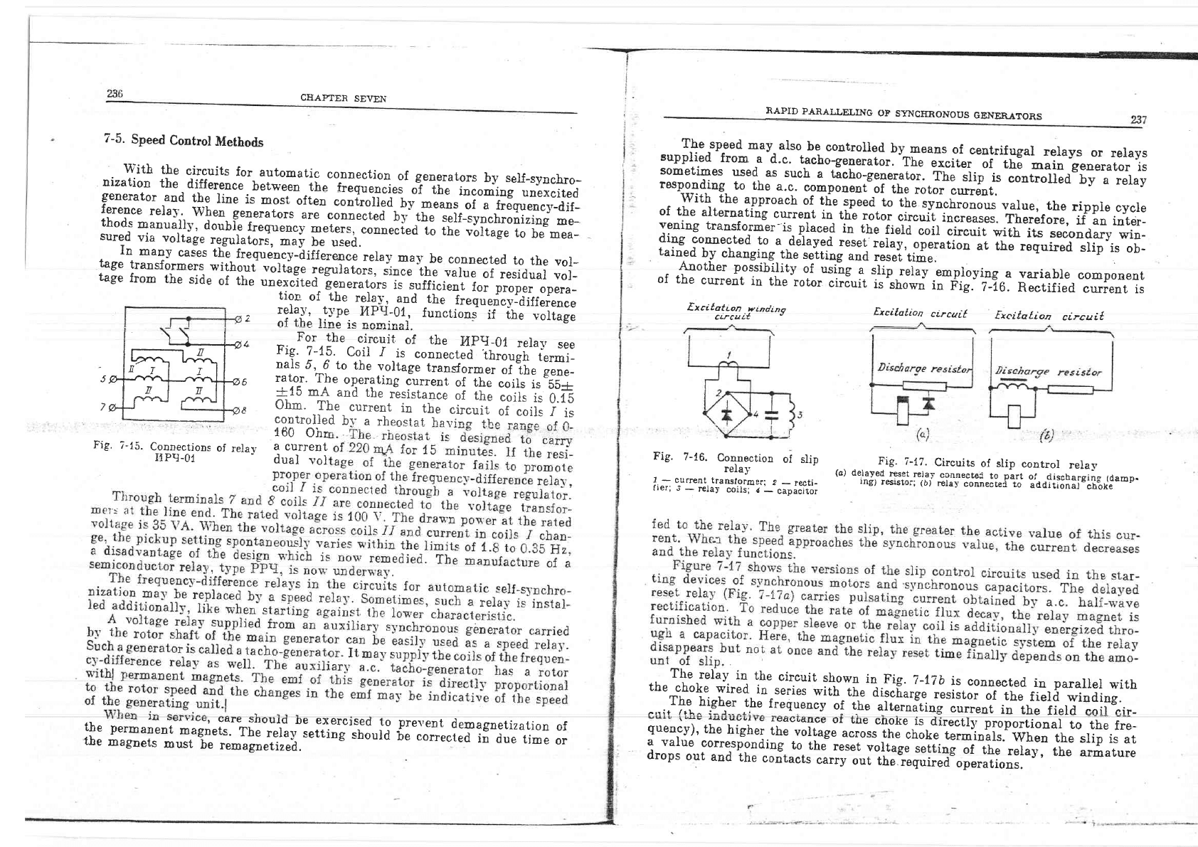
Fig.
7-i5.
Connectjons
of
relav
a
current
ilpg_of
-
dual
vol
Fig.
7-16.
Connection
ol
slio
relay
I
-
c,urrent
translormer;
2
_
re*ti-
fr€ri o'
-
r€Ia]
coiis;
I
_
capiCitor
Fig.
T-fZ.
Circuits
of slip
coatrol
relay
(a)
delaTed^rtse-t_re].a.r
-c^?l-lryEl
tg
part
ol-
.iiischarging
(damp.
lng)
reslstoi;
(b)
r€Iay
connectei
to
additional_ch*ot<e
The
relav
in
the
circuit
shown
il-Fig.
7_t|b
is
connected.
in parallel
rr_ith
the
choke
wired
in
series-il;h'iil-e
discfi..g,
,rrirtor
of
tue
zutd wind.iug.
.Tle
hish.er
the
frequtoty
of
l[r;il;;;iii"gLrrenr
in
the
fierd coil cir-
s.ed
19
prevent
demagnetization
of
should
be
eorrected
ii
au,
ii-,
o"
txcitotion
circuit
ti,e
perm
";;"r
;;;r[
"ri;",:#r'!-ffr
iT
the
magnets
must
-1,
,"-"l"rtir"a.
y,_::lli,^,0_.1*i,,
the
vortag;
"il;,"ffif:##l:"":i{"!il:iiTllToi"",l}-,i.f;
a
value
corresponding
ro
thJ
reset
yql;.g;,;ffid;
"f
-tnr'".irfl
iu"
armarure
drops
out
and
the
contacts
carry
out
the
required
operations.
CEAPTER
SEVEN
RAPID
PARAILELING
OF
SlAICERONOUS
GENERA"ORS
239
7-6.
Asyn_chronous
Connection
of
Generators
and
Parts
of
power
System
If
an
excited
gelerator,
whose
emf
is
E,
(see
Fig.
?4),
is
connected
to
the
power
svstem
busbars
under
a-"vnchrorou3
conditi;";
;;
;d;iil'ioe
current
arises
at
the
instant
of
connectio"n
rLE
cs:
--;--
xdgi
z"
an
unes.cite
t
generatorJ.
LE -
ZE'i
sin'.|
-
2U
"sin
$
The
calculation
of
t.he
maximum
value
of
the
tor
cument
in
as!'nchronous
connpction
(/;".;
;;"
tion
that
Et
=
Er:
(i.0b
_
t.tf
i;r.:as.m,
Le
lcomp-are
with
(Z-iS)
for
When
Ee:
Ea:
U"
permissible
torgue
multinlicitv
are
carried
out through
thl
mui
gf^^thg
asynchronous
connection
rdu
degrees
relative
to
the
Do_
periodic
cornponent
of
sta_
performed
frpm
the
assump-
(7-25)
(7-26)
(i-27)
three-phase
short
circujt
at
the
(7-28)
In
;?Y:::l':-(';?jl
"'d
(T-26)
eu
-
vsvuL'r
uure'rerlce
Detween
tbe
emf
of
an
asynchronou-"1\,
connpoterl
generator,
afier
the
direcr-axis
(inrushl
,"p.rtril;;i
;;ffi;;i;:
reactanc.e^.':J.t-"g:
.Ef;,
and the
circuit
voltage
tJ;
'ir
:
direct-axis
supertra".ieni
(i;r;.h)
l;dirctive
reactance
rs
:
inductive
reaetance
oi
ihe'p;";'ri;;;
The
as-vnchronous
connection
current
is at
its
msaipum
when
the
gene_
rator
is
connect:9,.1+
opposition
to
the
emf
of
an
equivalent
generator
of the
power
s-v-stem.
\\l;11
asynchronous
coanection
to
an
infinite_pon,er
sS,stem
(s, :
0) iraving
angie
6
5i&"jrnr.*
r
,,r.
o
-
2(L'05-
t'1)
{!
Ph'
n
o-"-EF--
(7-29)
u'here
t
:
::ilicient
which
account-s
for
the
emf
vectors
being
igO
deerees
,ra
I
or,
,:
+!
*dg
The short-circuit
cunent
in
tbe
case
of a
generator
terminals
Dn
f
"ti
rs.c:--
,dE
Short-Circuit
poner
yersus
Sl,stem
Voltaqe
System
.
voltage
Un,
kV
b.bort-ctrcuit
power,Ssc.
I\.IYA
b1'stem.
voJtage
Ur,
kV
Upto6
J000
220
,Ct35
Js00
110
5000
nol,
exc
il:.'-iJ:i.:'*T,:?,i;;*:'J',,_'-i"H.i:;iJ,'?;:
l1ffi,,lm'j,.
,Xl
*i,,*..*";
fntTlAftna+ia f^--',i.:^ rL- J-
.
.
The
circular
rl-ej
draws
attention
to
the
fact
that
connection
of
the
lines,
derermined
ty
;r;Gi*g
"iiv
15,000
re
thaB
330
96 nrtn
sometim
es
asynchronous
the
above-teuched
upon
ro
m
a
g
n
e t
i
c
tor q
u
0
-i
s th
e
d
ec
i s
i
v
J
i
r.
tli"
o r
"i
;#"f##r"
"Hff
uXT'
t*".t'r:J:
CE.APTER
SEVEN
US
GENERATORS
synchronous
operation
rx,hich
should
be
rs
specilied
in
soecial
instructions.The
tronous
connection
current
multipiicity
s.ions prove_
to
be
gredter
than
the pei-
;ion-q
nust
be
made
to
take
into
account
rynchronous
connections
are
calculated
.
From
(i'2J)
it
is cleariy
seen
that
asyqchro-nous
connection
of
a
single
gene-
rator
to
infinite-power
busbars
cannoi
be aliowed.
when iz:
ti-F;;
;;;;,
for example,
the
ratio
of-
asynchronous
connection
current
relative
to
the
no-
minal value
is
greater
thau
17.
Asynchrooor.-"oonection
of
generators
per-
forming^
a
joint
operatiou
through
a
transformer
and
a
tran-smission
line,
into_^a'fiaite-power
system,
someii-es
may
be
permitted.
If
there
is
a
group-
ol-paralleied
geoer"torc,
ihro-
oGo
simultaneous
svn-
chronous
eonugr.tinn
of a]-I-tUe
ppnhil^.
nf +L^'-----,^-
--!-:+
:- ---;--;;i--'--
\r./p" strqtortr rirotr lrn n^-al+{^J h"iT":-:t-r"-l
tst*ur
Pra''u
or
part
or
rne
po-
*er
rJrvujj.
ildi
iru
ljoi.iiiiLrea.
'ine
as:\Aehronous
Conneot,ion
current
deter_
mined
by
(7-29)
should
be
apportioned
"*oog
the
parallei.a
g.r.t*tors.
When
making
caiculations
the
minimum
possible"
num|er
of muJniaei
should
be
considered-
(i.t-,
the
most
severe
caie
from
the
point
of vien,
of
the
current
value
used
in
asynchronous
connection).
I
---
s-vstem.
For
the
resynchronization
ca
ous
connection
is
permissible
measures
wanted
operation
of
various
protec,tion
(see
Sections
4-7 and
8-3).
ynchronous
connection
mav
sometimes
ds
located
near
the
electric
centre and
power
piants
out
of
synchronism.
The-
s'hich
asynchronous
connection
may
be
with
a
preliminary
analysi-s
to
see whe-
nizarion
or
the
parts
or
the power
,rfr$"t*:ffi::|iXf,
Ti$t:TJ.?r,:Tu:i1T;
protective
relaying.
241
synchronous
itself,
after
.
The
next
rn
operation
f^oto.,.:
is
restored.
The
tl:
:."iid;
;;##;"itt
asvnchronous
laod
should
resrarr
by
i::ttlf^,giscusses.
the-
problems
of
a
n
d
th,
i"
-;;;;;#;,:;?,iiTr.,,?t
rf;
ff
,ls
l{j ilj" :
"
us
m
o tors
7-7.
Connection
of
SSrnchron!)us
Motors,
Prevenrinn
T"r.,
D;"pfffi
oi..st"p
and
Respchronizatio;
-
-"
"^
theS'
ari
p"tirJ
our
of
step.
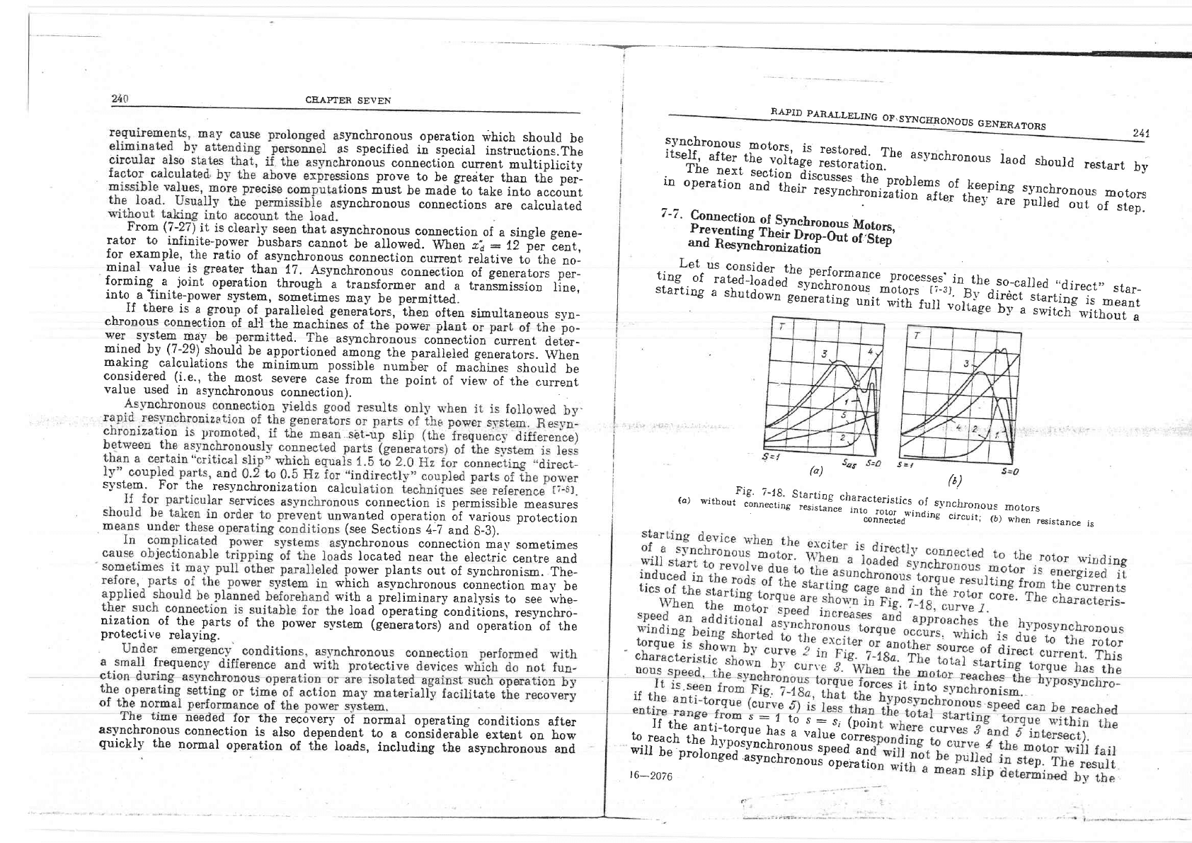
:*i-"iT'Er"-"fri:tjr*t'i;f,x1..-:ilis.i?:,,,"r,uii*":_l,l:"r-_,1:":,,,
srar-
starting
a
shutdown
.roh^F^+:_-
s
t
a
r r
i
ng
a
s
hu
t
d
o
wo
e.o
*uJil*
.lj',
r-,lfr'i#'1",?j;
ru
H:
i
:t*l;
jj
r:ifi
(")
Yc
(a)*,r0"",t'.*.;'"-.',1;.r:il:i:f
".",,,1T"r,.;,"1,T,,:i
jJ,
jrlronous
.onrll8l.o"'tttdins
circuit;
(b)
rnotors
when
resistance
is
asynchron"",;;l:h,l,"J*':,Jff
l:;:t;dtr"l;Tt"#,:lX',:T,,'"-i*lf
T"tlll
guickly
the
normal
operation
of
tfe
loads,
including
inr-*l'*hronous
and
"
iiJf
"*
TiT::i#.
T
;fi
J'.[ff;i
*i
i
J I^
p
"l
i"
ilil|i'j
Jr:lT*","".,
:r"T
jJii:
t6-2076