Bayer R.G. Mechanical Wear Fundamentals and Testing, Revised and Expanded
Подождите немного. Документ загружается.

accuracy to provide material ranking in a reasonable length of time. In ad dition, they were
also chosen to avoid complicating elements, such as excessive heating of the rubber
or degradation of the abrasive. In the standard test, different practices are defi ned for
different classes of materials to achieve these goals. Milder conditions are specified for less
abrasive resistant materials and coatings.
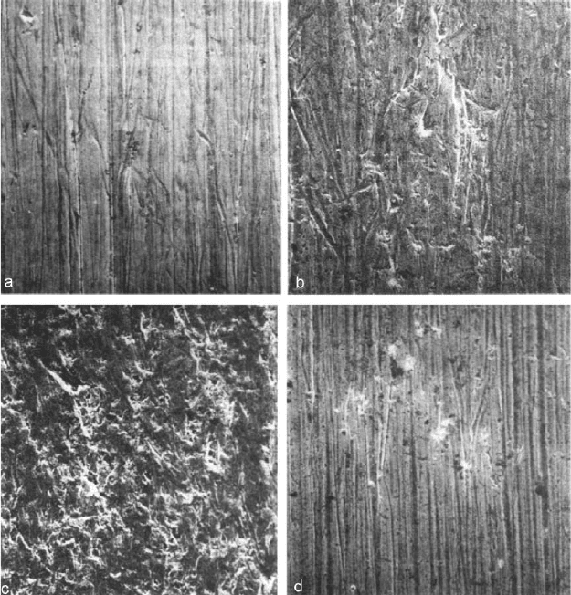
The ASTM test procedure also advises the visual examination of the wear scar to
insure that there is good alignment and no problem wi th the flow of abrasives. In addition,
the test method also uses tests with reference mate rials to insure consistency. The ASTM
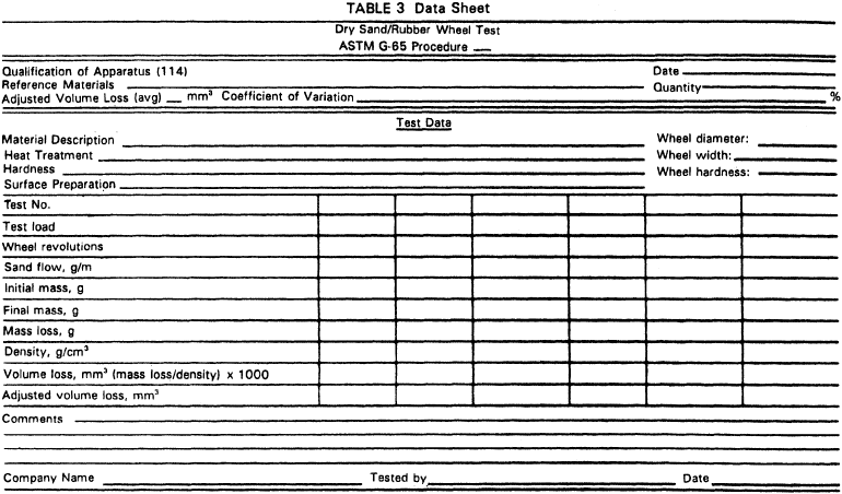
procedure also calls for the reporting and measuring of a number of parameters associated
withthetest.TherecommendeddatasheetisshowninFig.9.3
. This test configuration can
be used for other purposes other than ranking materials, such as evaluating the abrasivity
of different materials. When used in this fashion, the standard test procedure can be used
as a guide in establishing proper control, etc.
One point should be made regarding the weight loss method for wear determina-
tion used in the procedure. To provide valid comparisons, the volume of wear should be
used; this requires knowledge of the specimen’s density. If this is not done, ranking
might be in error because of density differences. This is of particular concern when
Figure 9.2 Examples of wear scar morphology from the dry sand–rubber wheel test. (From
Ref. 113.)
Copyright 2004 by Marcel Dekker, Inc. All Rights Reserved.
coatings are evaluated, since the densities of the coatings may be unknown. Therefore
othertechniques,suchascomputationofthewearvolumefromwearscar
dimensions,
might yield better resul ts.
An important element to recognize in this test is that while it simulates a wear
mode and correlates to field performance, it does not directly provide a wear constant
or parameter that can be applied to different situations. To determine absolute perfor-
mance in an application, a reference material for which there is field and test data must
be used and a scaling factor established for that application. This is because the test does
not address the question of relative severity in the test and in application, either on an
empirical or a theoretical basis. This is also the case in several of the other tests that will
be discussed. This implies that there is an unknown amount of acceleration provided by
the test and that the acceleration could be different for different applications. The
amount of acceleration that exists can be significantly dependent on differences in
the amounts and type of abrasives in the test and in application.
9.2.2. Wet Sand-Rubber Wheel Abrasion Test
This test also simulates low stress scratching abrasion and is very similar to the dry
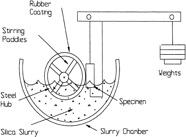
sand-rubberwheeltest.AdiagramofthewetsandtestisshowninFig.9.4
. It can be
seen that the basic test concept is very similar to the dry sand test, namely using a
rubber wheel to drag abrasives across the face of a wear specimen. In the wet sand test,
however, the abrasive is in the form of a water slurry. The wear in both tests is deter-
mined by weight loss and converted to volume for material rankings. Both tests have
been used extensively to investigate scratching abrasi on and both have been found to
correlate well with many practical applications (1–3). While there is the potential for
differences, similar material behavior is generally found with both tests. The wet sand
Figure 9.3 Data sheet for the dry sand–rubber wheel test. (From Ref. 114, reprinted with
permission from ASTM.)
Copyright 2004 by Marcel Dekker, Inc. All Rights Reserved.
test or test configuration offers an advantage in that the normal procedure can be
modified to utilize a slurry more representative of an application. In this way, chemical
effects associated with an application can be addressed.
As with the dry sand test, a standard version for material comparisons has been
developed by the ASTM (ASTM G105). Similar repeatability is found with both the
wet and dry sand tests when the procedures are followed. A coefficient of variation of
5% is characteristic of the wet sand test. To achieve this, the test procedure controls many
of the same factors that are controlled in the dry sand test. These include design and
construction of apparatus, measuring techniques, specimen tolerances and preparation,
and rubber wheel and abrasive specifications. A procedure and interval for dressing the
rubber wheel are also given. However, some of the approaches used are different.
As with the dry sand test, the feeding and control of the abrasive is a significant
factor in the test. Composition of the slurry is defined in terms of abrasive size, type
and source, and the type and amount of water. A uniform supply to the interface is
achieved by having the contact below the surface of the slurry. To maintain uniformity
of the slurry during the test, paddles on the side of the wheel provide agitation
(Fig. 9.4). The test procedure also requ ires that the wear specimens be demagnetized prior
to the test. This is to avoid problems with magnetic wear debris adhering to the wear
surface or clustering in the slurry.
In the wet sand test, three rubber wheels of different duromet er (A50, A60, and
A70 durometer) are used to minimize the effect of wheel variation. This is done by using
the wear obtained with these different durometer wheels to define a best-fit linear
relationship between durometer and log of the wear. The value of wear reported for
the test is that obtained for A60 durometer from that curve. Graphically, this is
illustratedinFig.9.5
.
Another difference between the two tests is that the wet sand procedure requires a
break-in cycle with the A50 durometer wheel. This is to minimize the effects of surface
Figure 9.4 Sketch of the wet sand–rubber wheel test.
Copyright 2004 by Marcel Dekker, Inc. All Rights Reserved.

defects and variations. After each of these tests, including the break-in, it is specified that
the slurry chamber be cleaned and new slurry used. The technique also requires reposition-
ing of the specimen, which is controlled by the fixturing and associated tolerance. Visual
inspections and statistical criteria are associated with the procedure as well. For example,
tolerance on the correlation coefficient for the linear fit is specified. Also, if the coeffi-
cient of variation is beyond 7%, the test is considered out-of-control and the test procedures
and apparatus should be examined to determine the reason for this condition.
Like the dry sand test, the wet sand provides a ranking of materials but does not
provide absolute values. Different test conditions are specified for different classes of
materials to provide suitable resolution and separation in wear resistance.
9.2.3. Slurry Abrasivity
This test is also associated with low stress scratching abrasion. However, it was primarily
developed to address slurry abrasion problems in pipelines, which handle slurries. It has
been used extensively for these applications with good correlation (4,5). The initial focus
for this test was to rank the abrasivity of the slurries encountered, but the test method was
expanded to provide a ranking capability for wear resistance against a particular slurry.
For the former, the test results in what is termed a Miller Number; for the latter, a
SAR Number. SAR stands for slurry abrasion response. Both are based on a weight loss
technique for measurement of wear, although a wear rate is used for ranking. This test
is also an ASTM test procedure (ASTM G75).
The basic configuration of the test is a flat rectangular wear specimen sliding back
and forth across a rubber lap, flooded by a slurry; both the wear specimen and the lap
aresubmergedintheslurry(Fig.9.6
). The flat wear specimen is mounted on an arm, which
moves it back and forth at a controlled speed. The arm lifts the specimen at the end of each
Figure 9.5 Illustration of the method of analyzing wear data in the wet sand–rubber wheel test.
(From Ref. 3.)
Copyright 2004 by Marcel Dekker, Inc. All Rights Reserved.
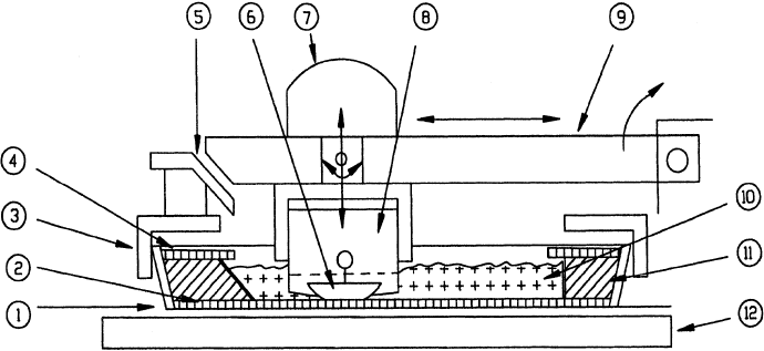
stroke to allow the slurry to come between the specimen and the lap. The tray that holds
the slurry has tapered sides so that with the motion of the wear specimen, mixing and cir-
culation of the slurry occurs. The wear specimen is removed periodically and weight loss
determined. By varying the slurry and keeping the wear specimen constant, the abra-
sivity of slurries can be ranked. This is essentially the Miller Number. By keeping the
slurry constant and varying the wear specimen, wear resistance of different mate rials
to that slurry can be ranked. This is used to generate the SAR Number.
The reproducibility of the test is good, as the coefficient of variation is approximately
6% for the Miller Number and 12% for the SAR Number. The larger value for the SAR
Number reflects the decrease in control that this version of the test has. A carefully
controlled reference wear specimen is used in the Miller Number test, whereas in the
SAR version the wear specimen is simply a material of interest. One element contri-
buting to this increased variation would be lack of precision in the value for specific gravity
of this specimen; other factors are variation and nonuniformity in other material
properties, such as composition and grain structure.
The test procedure associated with each of these tests involves a well-designed and
specified test apparatus, cleaning and specimen preparation steps, specifications and
controls on the materials involved, and carefully outlined steps for conducting the test.
The test method calls for replacement of the rubber lap with each test to avoid problems
associated with degradation and co ntamination of the lap. In particular, extensive details
are provided to insure proper alignment of the wear specimen to the lap, including a
method of checking alignment prior to the start of the test. Procedures for preparing
the slurry are also given.
The analysis method involves the developing of a wear curve and using a wear rate to
rank either the abrasivity of the slurry or the abrasion resistance of a material to a given
slurry. Measurements are made after 4, 8, 12, and 16 hr. Using a least square method, the
wear data obtained are fitted to the following equation:
mass loss (mg) ¼ A t
B
ð9:1Þ
Figure 9.6 Sketch of the slurry abrasivity test apparatus. 1, Molded plastic tray; 2, neoprene lap; 3,
tray clamp; 4, splash guard; 5, block lifting cam; 6, standard wear block—27% Cr-iron; 7, dead
weight; 8, adjustable plastic wear block holder; 9, pivoted reciprocating arm; 10, sand slurry; 11,
molded plastic filler ‘‘V’’ channel; 12, tray plate.
Copyright 2004 by Marcel Dekker, Inc. All Rights Reserved.
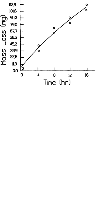
where t is time. Using the value of A and B obtained in this manner, the wear rate (mg =hr)
atthe2hrpointisdetermined.ThismethodisillustratedinFig.9.7
. The wear rate is then
multiplied by a scaling factor of 18.18 hr=mg to provide the dimensionless Miller Number.
The higher this number, the more abrasive the slurry is. The scaling factor was determined
so that the Miller Number of a reference slurry of sulfur is 1 and of a reference slurry of
corundum is 1000.
The method of analys is is the same for the SAR Number. However, the wear rate at
the 2 hr point is multiplied by the scaling factor and the ratio of the specific gravity of the
reference material to that of the test specimen
SAR Number ¼ (wear rate at 2 hr) 18:18 ðh=mgÞ
7:58
p
ð9:2Þ
where p is the specific gravity of the test specimen. To reduce scatter, the method of
analysis uses the average value of two runs for the fit. The test apparatus is usually built
with two separate trays so that two tests can be performed at the same time. In addition,
the test procedure calls for the samples to be rotated 180
between each measurement to
reduce effects of misalignment and orientation. Since separat ion of the slurry can occur
while these measurements are made, the procedure requires stirring of the slurry prior
to continuing the test.
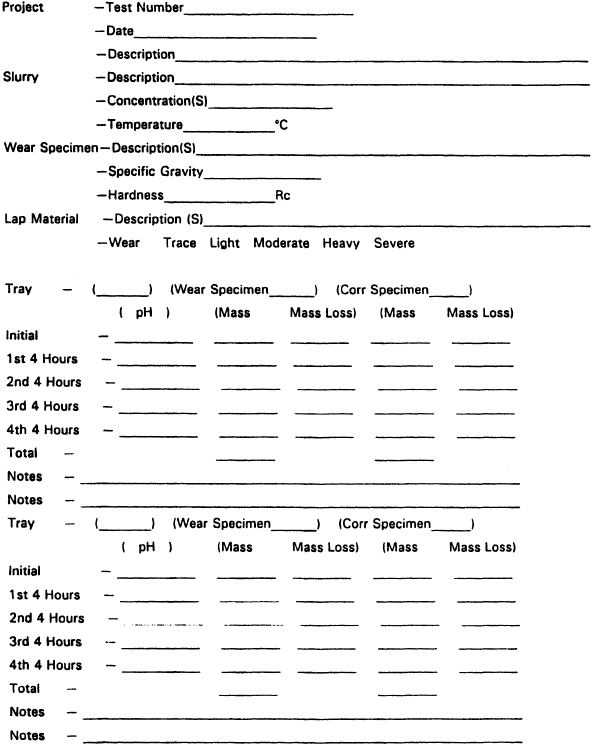
TheformatforreportingtheresultsofthetestisshowninFig.9.8
, which shows that
more data and observations regarding the test are recorded than simply the mass loss of
the wear specimen(s). Included in this are the temperature and pH of the slurry, observa-
tions regarding the degree of wear seen on the lap, and a detailed identification of the
slurry used in the test, including the preparation technique of the slurry. The recom-
mended slurry for the test is a 50% mixture of the solid extracts from the slurry in question
and water. However, the procedure allows the use of other types of slurries, such as the
slurry in question or the mixing of the dry extra cts with other media.
The test parameters and procedures were selected and developed with the use of
additional studies, aimed at insuring simulation with the intended application, minimum
scatter, and a convenient test (4–6). One focus of the studies was the influence of
Figure 9.7 Example of the method of analysis used in the slurry abrasivity test. The curve repre-
sents the least squares fit of the data, using Eq. (9.1). Best fit values of A and B are, respectively,
13.4262 and 0.749182, which result in a wear rate of 8.47 mg=hr at 2 hr and a Miller Number of
154. (From Ref. 6.)
Copyright 2004 by Marcel Dekker, Inc. All Rights Reserved.
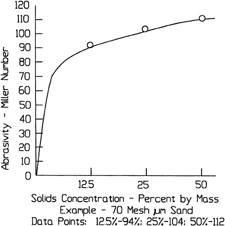
concentrationandslurrymedia;anonlineareffectwasfound(Fig.9.9). The Miller
Number becomes less sensitive to concentration as the concentration increases. This
means that performing the test at higher concentration can minimize variation. The use
of higher concentration also enhances simulation in that many of the applications involve
high concentration (e.g., in the 50% range).
These same studies also showed effects associated with the liquid phase of the
slurry. For example, oil-based slurries tend to result in lower wear than water-based slur-
ries. Some of this behavior can be associated with the different fluids providing different
lubrication and dispersion. In addition, this type of behavior can also be the result of
differences in chemical or corrosion effects that occur with different fluids. Several things
were done to control this element in the test. One was to use a design, which employed
the use of nonconducting materials to eliminate electrochemical effects; another was to
use a chromium iron, which is used in some applications and is somewhat corrosion
Figure 9.8 Format for reporting wear data in the slurry abrasivity test. (From Ref. 6, reprinted
with permission from ASTM.)
Copyright 2004 by Marcel Dekker, Inc. All Rights Reserved.
resistant, as the standard material for the Miller Number . These effects also influenced
the selection of a water=dry solids mixture as the preferred slurry for the test. However,
because of the varied and uncontrolled ionic nature of the dried solids from various
applications, these do not necessarily eliminate corrosi on effects from tests. To help
separate and assess the significance of corrosion on the test results, it is suggested that
a second test be done with a slurry specifically buffered to eliminate corrosion. This
concern is reflected in the pH data requested in the data sheet. It also underscores the
desirability to test with the actual slurry from an application to enhance simulation
and the use of the SAR Number test. Since the material of interest is tested in the
SAR Number test, the specific corrosion effects on that material are included in a test
with the actual slurry. It can also be seen that both the SAR and Miller Numbers must
be referenced to a parti cular slurry.
The use of several different test conditions suggested with the slurry abrasion test
procedure illustrates the need in some cases to modify standard wear tests to improve
correlation with an application.
The primary intention of both the dry and wet sand test and the slurry test is to rank
materials in terms of their abrasion resistance. Neither the wet nor the dry sand test is as
sensitive to the corrosion element as the slurry test. In the dry sand test, it is eliminated
since a fluid is not used. In the wet sand test, corrosion effects are limited by the use of
a nonionic abrasive in water. From a test for pure abrasion resistance standpoint, the
dry and wet sand tests have some advantage in that the wear situation is less complex.
However, from an application standpoint, they may be poorer since the actual situation
may involve corrosion. Consequently, in performing evaluations for an application, which
involves fluids, the slurry test provides the better simulation in that the confounding effects
of corrosion can be assessed. This may or may not be significant, depending on the relative
degree of pure abrasion and corrosion, in any given situation.
Figure 9.9 The effect of slurry concentration on the Miller Number. (From Ref. 6.)
Copyright 2004 by Marcel Dekker, Inc. All Rights Reserved.
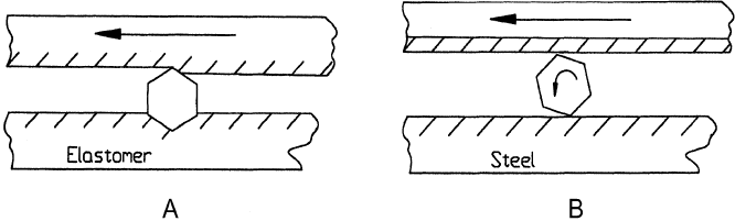
These three tests, dry and wet sand, and slurry abrasivity, have a common feature in
that they use a rubber lap as a counterface. In simulating low stress scratching abrasion,
the use of rubber as a counterface has an advantage in the way that it helps to reduce the
stress on the abrasive pa rticle and thereby to reduce fracture. Also, since they tend to
provide large contact area with the particles, they tend to preferentially hold the particles
anddragthemacrossthewearspecimen.Figure9.10
illustrates this for both a rubber and
rigid (e.g., steel), counterface. This action plus the use of a much larger surface area for the
rubber counterface results in preferential wear of the wear specimen. These two effects
account for the apparent superior abrasion resistance of the rubber laps in comparison
with the much harder materials evaluated in these tests. However, in a situation wher e
the abrasive would be dragged across the rubber surface, the rubber materials would show
a large reduction in wear resistance and inferior behavior to many of the mate rials
evaluated in the test.
The slurry abrasion test allows for different procedures for different material
categories. It does not provide absolute values of wear performance but rather a material
ranking.
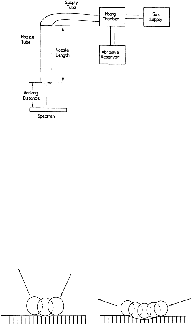
9.2.4. Erosion by Solid Particle Impingement Using Gas Jets
Gas jets have been used to investigate solid particle erosion and to rank materials in
termsofresistancetothismodeofwear(Fig.9.11
). It has been found to correlate well
with erosion situations characterized by near normal particle impacts, such as erosion of
valves in coal gasification and similar equipment (7,8), but not with situations which
involve grazing impacts. Examples of these latter situations would be erosion by
wind-blown dust and erosion of airfoil surfaces. Differences in the impingement condi-
tionsforthesecasesareillustratedinFig.9.12
. The effect of incident angle on wear scar
morphologyisshowninFig.9.13
.
Using the conditions and procedures for this type of test outlined in ASTM G76,
coefficients of variation in the range 5–20% are achievable. The standar d conditions for
thetestareshowninTable9.1
,which lists the significant parameters to be controlled
in the test and tolerances are specified for each. The test procedure also requires the
routine use of a reference material and the monitoring of the nozzle for signs of wear
(erosion). If the diameter of the nozzle increases by 10% or more, the nozzle is to be
replaced. Procedures for specimen preparation, cleaning, and repeatability are also
addressed in the standard.
Weight loss is the method used for determining the amount of wear that occurs.
However, the resi stance to erosion is measured in terms of the wear volume per gram
Figure 9.10 Behavior of abrasive particles trapped between two surfaces, which are sliding relative
to one another. ‘‘A’’, when one surface is an elastomer; ‘‘B’’, when both surfaces are metals.
Copyright 2004 by Marcel Dekker, Inc. All Rights Reserved.
of abrasive. This is obtained through the use of a wear curve that is generated by
measuring the mass loss at different time intervals . The slope of this curve is then used
to determine an average wear rate. Examples of wear curves obtained in this test are
showninFig.9.14
. The mass loss rate is converted to a volume loss rate by dividing
by the density of the specimen. This volume wear rate is then normalized to the abrasive
flow rate to provide the erosion value, which is defined as wear volume per gram of
abrasive. The smaller the erosion value, the more wear resistant the material. Guidelines
for the test duration are provided with the intention that the measurements be made in a
period of stable wear behavior. Since 2 min or less is typically required for stabilization,
it is specified that the first measurement be taken after 2 min. The test should be carried
out for at least a total of 10 min but should not go beyond the point where the scar
depth exceeds 1 mm. The reason for this limit is that beyond that depth the shape
ofthescarbecomessignificantindeterminingimpactangle.Figure9.15
shows a typical
scar and the effect of wear geometry on angle of impac t.
The data and information that are to be recorded and reported in conjunction with
theerosionvalueareindicatedinFig.9.16
. When nonstandard test conditions are used,
Figure 9.11 Schematic of the solid particle erosion test.
Figure 9.12 Comparison of near-normal and grazing-normal particle impact.
Copyright 2004 by Marcel Dekker, Inc. All Rights Reserved.