Bayer R.G. Mechanical Wear Fundamentals and Testing, Revised and Expanded
Подождите немного. Документ загружается.

the accuracy required, provide proper alignment, and rotational control. Since galling is
an adh esive phenomena, proper cleaning of the specimens is a critical factor in this test
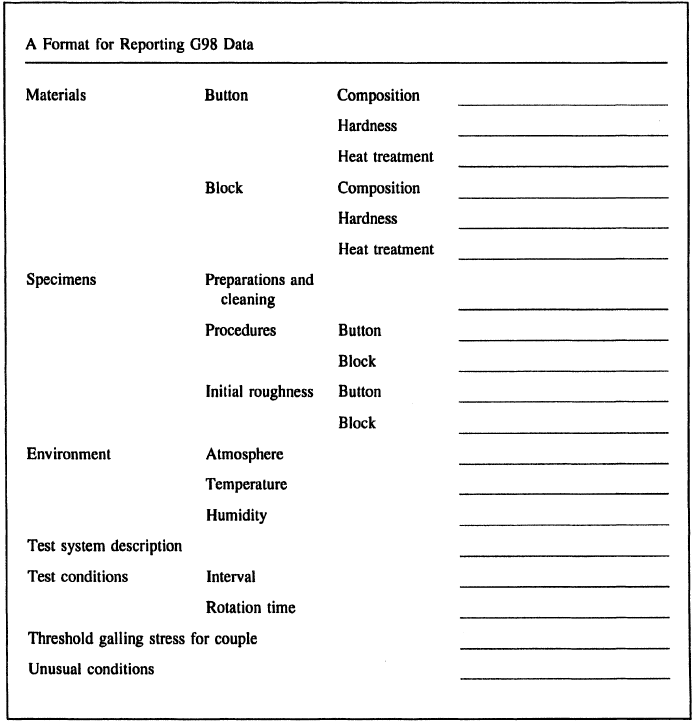
and this is emphasized in the test procedure. The information that should be reported with
resultsisshowninFig.9.32
. The method also provides guidance as to how to examine the
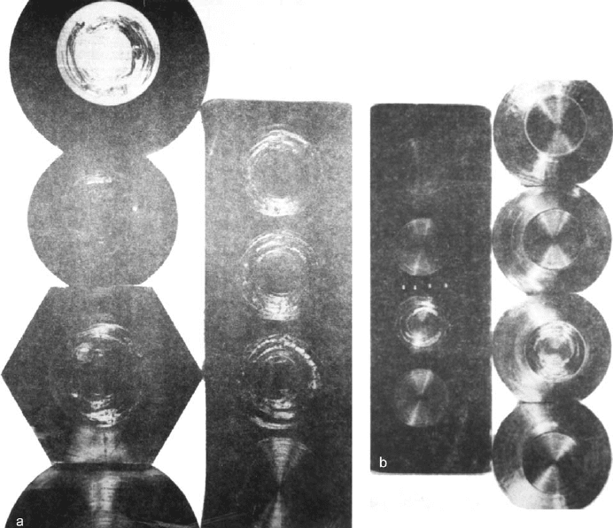
surfacesforevidenceofgalling.ExamplesfromthistestareshowninFig.9.33
.
This test is an example of one in which the appearance of the worn surface is used to
evaluate the wear resistance of materials. When such an approach is used, it is necessary to
define the type of technique to be used in evaluating the appearance. One aspect of this is
magnification. Different techniques could enhance or degrade the identification of certain
features and variations in precision would result. In additi on, different techniques might
be sensitive to different aspect s of the phenomena and in effect would result in varying
criteria. To address these co ncerns, the test method specifies unaided visual inspection for
determining whether or not galling has occurred. While qualitative approaches, like the
one used in this test, are more subjective than quantitative approaches and as a result tend
to be less precise, they can be effective and consistent. Good inter and intralaboratory
Figure 9.32 Data to be reported in the ASTM test for galling.
Copyright 2004 by Marcel Dekker, Inc. All Rights Reserved.
reproducibility has been found in interlaboratory testing done for the development of
the ASTM standard. Experience has shown that a 5–10 kpsi difference in the galling thre-
shold stress is needed before a difference in field perfor mance is observed. Interlaboratory
testing programs, utilizing this standard method, generally have shown repeatability
within that range.
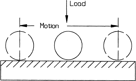
9.2.10. Rolling Wear Test
A configuration that has been successfully used to address rolling wear is illustrated in
Fig.9.34
. Basically, it consists of a pair of driven rollers pressed against one another.
The typical procedure is to visually monitor the condition of the roller surfaces and deter-
mine the number of cycles for a selected level of surface damage to occur. This could be the
appearanceofcracks,surfacetexturechange,orspalls.Figure9.35
illustrates examples of
this type of damage and wear. These tests are usually quite long, extending for days or
weeks and inspections are done on a periodic or scheduled basis. This is another example
of the use of appearance criteria in a wear test. The longer the number of cycles, the more
resistance the pair is to rolling wear.
Critical elements of this test are control of the surface velocities of the two rollers,
alignment of the rollers, and geometrical tolerance of the rollers. With respect to the last,
Figure 9.33 Examples of wear scars produced in the test for galling. ‘‘A’’ shows examples of sur-
faces exhibiting galling in the test. ‘‘B’’ shows the results of a test sequence used to determine the
galling threshold. (From ASTM G98, reprinted with permission from ASTM.)
Copyright 2004 by Marcel Dekker, Inc. All Rights Reserved.
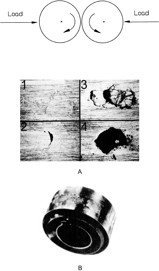
Figure 9.35 Examples of wear produced in a rolling test. ‘‘A’’ shows various stages in the forma-
tion of a single spall. ‘‘B’’ shows the appearance of the surface of a roller with extensive spalling.
(‘‘A’’ from Ref. 18, reprinted with permission from NLGI; ‘‘B’’ from Ref. 27, reprinted with
permission from Penton Publishing Co.)
Figure 9.34 Basic configuration used in rolling wear tests.
Copyright 2004 by Marcel Dekker, Inc. All Rights Reserved.
particular attention has to be paid to the edge conditions of the rollers so that a significant
stress concen tration condition does not occur. This means that the edges of rollers should
be well rounded. Use of rollers of the same length can help to minimize this exposure, as
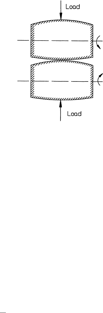
well. Another approach that has been used is to use slightly curved or crowned rollers,
asisshowninFig.9.36
. This type of test has been used to address conditions of pure
rolling, in which case the surface velocities of the two rollers must be identical. In addi-
tion, the test has also been used to address conditions of mixed rolling and sliding. In this
case, the relative velocities must be control led so that the proper ratio of sliding to rolling
is achieved and maintained. There are two elements to controlling the velocity; one
element is the rotational speeds of the two rollers. The other is the radius of the rollers.
In addition, control of the preparation and cleaning of the rollers are important, as well
as the consistency and uniformity of the materials and lubrication, if used.
This test has been used for the evaluation of material pairs for rolling applications
such as gears, cams, roller bearings, and ball bearings. In these types of applications,
additional forms of wear might also be present. For example, different regions of gear
teeth are exposed to different modes of wear. Rolling predominates along the pitch line,
while sliding predominates at other locations along the tooth profile. Nonetheless,
generally good correlation has be en found between this test and actual performance
for those regions where rolling is the major characteristic. One way in which this type
of test has been used is to develop data in conjunction with a model for rolling wear
(27,28). The basic concept of that model is that there is a power law relationship between
the number of cycles to failure and the stress level under which rolling takes place, as per
the following equation:
N ¼ N
o
S
S
o
n
ð9:5Þ
N is the number of cycles to failure at stress level S and N
o
is the number of cycles to
failure at stress level S
o
. The parameters of the model that need to be determined experi-
mentally are N
o
and n. This can done by performing a series of tests at different stress
Figure 9.36 Configuration of a rolling wear test in which curved rollers are used.
Copyright 2004 by Marcel Dekker, Inc. All Rights Reserved.
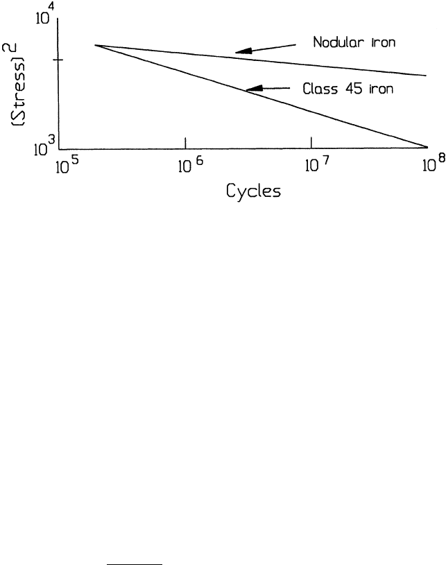
levels and determining the number of cycles to failure for each of the stress level. By fitting
these data to Eq. (9.5), the values can be determined or a curve defined that represents that
type of equation. Examples of several curves characterizing pairs of material s are shown in
Fig.9.37
. This is a log–log plot and Eq. 9.5 is a straight line on such a plot. Consequently,
a mini mum of two tests at different stress levels is required to define the parameters.
It is generally desirable to do repeated tests and ones at additional stress levels. The
differences in stress levels and number of repetitions should be large enough that a good
estimate of n can be obtained. Changing geometry, size, or load can vary stress level.
However, it is usually more convenient and preferred to perform tests at different loads,
since specimens can then be made to a single size and shape. Changing size and shape
may introduce or change other factors, particularly the amount of slip and alignment,
which can result in increased variability or scatter.
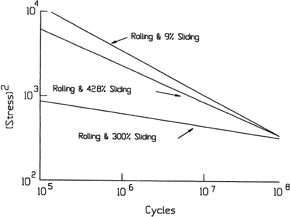
The same basic test and procedure is used with different amounts of sliding intro-
duced.ExamplesofcurvesobtainedforthesemixedconditionsareshowninFig.9.38
.
Again, the data are fitted to Eq. (9.5). In general, different values of N
o
and n are obtained
for different percentages of sliding. The percentage of sliding is defined as
% Sliding ¼ 2
jV
1
V
2
j
jV
1
þ V
2
j
100% ð9:6Þ
where V
1
and V
2
are the surface velocities of bodies 1 and 2, respectively. At some
percentage of sliding, the morphology of the wear changes to one more characteristic of
sliding wear (e.g., scratches, scuff ed appearance, adhesion, etc.). This would represent a
limiting value for the rolling wear model. This transition point can be established by
performing tests at different percentages of sliding and looking for this type of change
in morphology. Since the value of this transition point can vary significantly with materials
pairs (e.g., 9–300%), it is often of engineering significance.
Testing in this fashion (i.e., to determine values of parameters of a model) provides
the test with the element of being able to determine absolute performance, as well as accel-
eration. Eq. (9.5) can be used to predict or project actual performance if the stress level in
the application is known. Acceleration is provided by being able to define N
o
and n in
shorter periods of time by performing tests at stress levels above those in the application.
For the simulation of application, it is important to insure that the stress levels in the
Figure 9.37 Examples of the relationships between stress and number of revolutions obtained in
rolling wear tests with different materials. (From Ref. 27.)
Copyright 2004 by Marcel Dekker, Inc. All Rights Reserved.
test remain in the same range as that of the application. Generally, this means that the
loads used in the test should result in stresses in the elastic range. If the test loading is
such that plastic deformation occurs, the test method is not valid. This can be a practical
problem for some materials, like thermoplastics. For these materials, stress levels required
to avoid creep or deformation might result in very long test times and it may not be a
practical way to evaluate these materials.
9.2.11. Reciprocating Pin-on-Flat Test (Oscillating Ball-Plane Test)
Generically this test is very similar to the pin-on-disk test and used for the same purposes.
It differs only in the type of motion. The generic features of a reciprocating pin-on-flat or
ball–planetestareshowninFig.9.39
. One difference between the flat and disk tests is the
shape of the flat member of the contact. In the pin-on-disk, it is a disk to accommodate
rotation, while with the flat and plan test configurations, it is normally a rectangular block
or flat specimen. However, the fundamental difference is with the type of motion that each
provides. The motion is generally unidirectional at a constant speed in the pin-on-disk
test. In the pin-on-flat test and ball-on-plane test, there is a reversing of the direction of
sliding and the speed may vary throughout the cycle. One of the consequences of the
change in directions is that each cycle contains acceleration and deceleration portions,
an element that is not present in the pin-on-disk test. The velocity profile tends to vary
with different apparatuses and depends on the nature of the drive mechanism used. For
example, the profile is sinusoidal if a rotating eccentric is used. If a linear stepper motor
is used, it would have a square wave profile. These differences in the motion can influence
wear behavior for a variety of reasons including the influence of debris, build-up of trans-
fer and third-body films, lubrication, and fatigue wear mechanisms (which ca n be influ-
enced by stress reversals). Consequently, the motion in one type of test could provide
Figure 9.38 Examples of the relationships between stress and number of revolutions obtained in
rolling tests involving slip. (From Ref. 27.)
Copyright 2004 by Marcel Dekker, Inc. All Rights Reserved.
better simulation for an application than the motion in the other type. While this potential
exists and must be recognized, it generally does not appear to be a major factor. Both tests
have been used effectively to address wear concerns in both unidirectional and oscillatory
applications.
It is also desirable to measure friction in conjunction with a pin-on-flat or ball-on-
plane wear test, as it is with the block-on-ring and pin-on-disk tests. Therefor e it is a good
practice to incorporate this capability into these types of apparatuses. Many of the ones
described in the literature (29) have this capability. One advantage or use of these
oscillating tests is that its oscillatory nature makes it suitable for the simulation of fretting
or fretting corrosion situations. This is done by reducing the amplitude of the motion
to the range of associated with fretting (30,31).
Like with the pin-on-disk test, these reciprocating test s can be used to rank material
pairs in terms of wear resistance. ASTM G133 describes a standard test method for such a
purpose, which utilizes a sphere or spherical-ended pin. Like the ASTM test method for
pin-on-disk, ASTM G99, wear volume after a fixed amount of exposure (number of cycle)
is used. The coefficients of variation from interlaboratory test programs are between 20%
and 30% within a laboratory and about 50% between laboratories. This test method and
ASTM G99 (pin- on-disk test) are useful guides for conducting these types of tests. The
ball–plane test has also been used in a different manner to address engineering wear situa-
tions (30–35). With these uses the same methods for providing control apply but with
some modifications that are associated with the taking and analysis of the data. However,
the measurements made and the analysis techniques tend to be different for these two uses.
If the standard method is used, the volume of wear generated after a specified amount of
sliding is used to rank the material pairs (with the caution that the wear curves in these
tests are frequently nonlinear). In the engineering use, a linear wear dimension (e.g., such
as scar width or depth) is often used and a wear curve developed, rather than a single
measurement.
The following is a description of a method that can be used for engineering evalua-
tions with a ball–plane test and extended to the pin-on-disk test as well. In addition,
some elements of this approach can also be applied to the block-on-ring test. In many
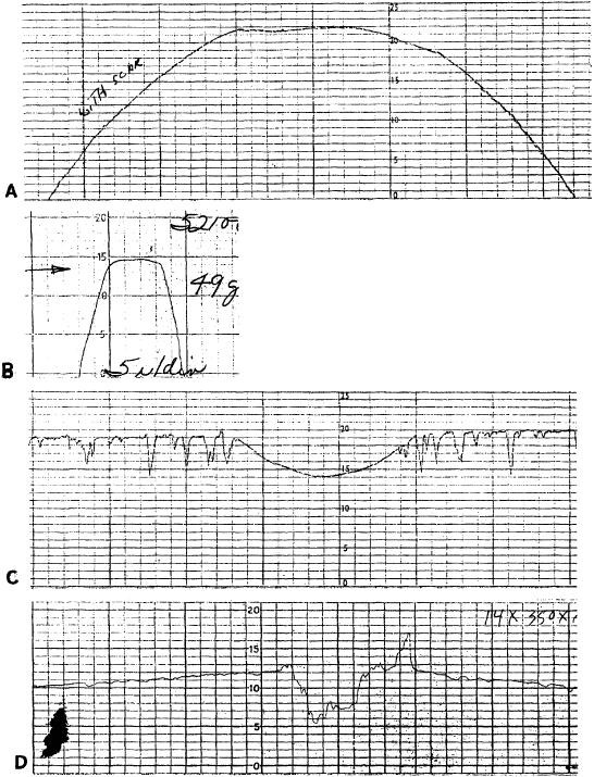
of the engineering applications of this test, the primary wear measure is the depth of the
wear scar. This is usually determined by means of a profilometer measurement. Fig. 9.40
shows typical traces for the ball and the plane. With the plane, the trace automatically
Figure 9.39 Configuration of reciprocating pin-on-flat test, using a spherical specimen as the
‘‘pin’’. The shapes used for the pin are the same as with the pin-on-disk test. (See Fig. 9.25.)
Copyright 2004 by Marcel Dekker, Inc. All Rights Reserved.
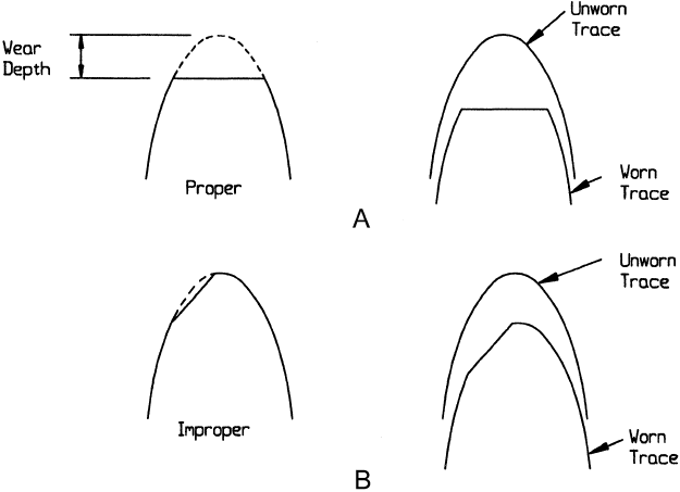
provides a reference level to determine wear depth. For the ball, some technique com-
paring the unworn profile with the worn profile is often used. A graphical over-lay tech-
niqueisshowninFig.9.41
for a flat wear spot on the ball and for a more general
condition in Figs. 9.28 and 9.30. Analytical techniques, which are based on the measure-
ment of the width of the spot, can also be used (36). To improve accuracy with an over-
lay technique, it is desirable to use unworn profiles of the actual specimen rather than a
theoretical or nominal shape.
The method involves the use and analysis of a wear curve, generally plotted on a
log–log scale. Conducting tests of different duration generates the wear curve. The inter-
vals and overall duration of the test vary with the situation or application being
addressed. The concept is to generate a well-defined wear curve which is representative
of the wear in the application. As a rule, this means adjusting the total measurement
interval to extend from the smallest amount of sliding required to produce a measurable
Figure 9.40 Profilometer traces across wear scars occurring in ball–plane wear tests. ‘‘A’’ and ‘‘B’’
are for the ball specimen; ‘‘C’’ and ‘‘D’’, for the plane surface. The radii of the spheres used and the
magnifications of the traces are different.
Copyright 2004 by Marcel Dekker, Inc. All Rights Reserved.
wear depth to that required to produce a significant increase in the wear depth (e.g., for
example an order of magnitude increase or more). It is generally appropriate to select
logarithmic or half-logarithmic intervals since the wear depth typical increases in a less
than linear fashion. To characterize the wear behavior the data are then fitted to a
power relationship
h ¼ C S
n
ð9:7Þ
where h is the depth of wear and S is the amount of sliding, number of cycles, or time. This
is usually best done by plotting data on log–log paper and fitting the log-form of Eq. (9.7)
to the data. Best-fit values for C and n are used to characterize the wear behavior of the
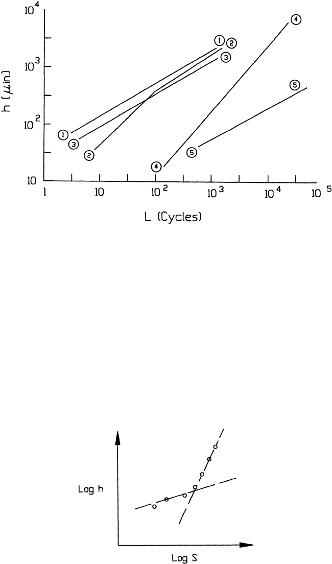
system.TypicalwearcurvesobtainedinsuchafashionareshowninFig.9.42
. In effect,
the standard test method only uses C for this characterization, which presumes that n
is a constant.
There can be poor correlation between the wear data and Eq. (9.7) in some instances,
as in one of the cases shown in Fig. 9.40, curve 2. In such cases, the wear data are fitted in a
piece-wise fashion. Usually, it is sufficient to separate the data into tw o regions, such as
initial and long-term behavior. The data in each region are fitted by an expression of
theformofEq.(9.7)(Fig.9.43
). In such cases, there is a significant difference in n for
the two regions. Generally, this piece-wise fit is necessary as a result of transitions
in wear behavior, which can be associated with observed changes in friction and wear
scar appearances . In some cases, additional regions may need to be considered in the
same manner (34).
Once the wear curve is defined in terms of one or more pairs of C and n values, the
results can be interpreted in terms of various models or theories. These models can then be
Figure 9.41 Illustration of the overlay technique used to determine wear depth on a curved surface.
‘‘A’’ shows the proper technique; ‘‘B’’, an improper technique. In using the technique, the wear scar
should be at the apex of the trace.
Copyright 2004 by Marcel Dekker, Inc. All Rights Reserved.
extended to the a pplication. The following example for the case of a flat spot being
worn on a ball illustrates this type of consideration. Because of the geometries involved,
a linear relationship between S and wear volume results in a value of n close to 0.5. If
the value obtained for n is close to this, it would imply stable wear behavior, as well as
the wear being consistent with models for abrasive and adhesive wear. However, if a value
of n significantly greater than 0.5 were obtained, this would impl y that there is some
transition in wear occurring, as is illustrated in Figs. 9.43 and 4.46. Likewise if a value
of n lower than 0.5 is obtained, this suggests a wear mode, referred to as a variable energy
wear mode, which is associated with fatigue wear and stress-dependent, is dominant (24).
Figure 9.43 Example of the piece-wise fit of wear data to relationships of the form, Wear ¼ K
Usage
n
.
Figure 9.42 Example of wear curves obtained in ball–plane tests. Curves 1, 2, and 3 are for the
depth of wear on a steel sphere sliding against ceramic flats of different roughnesses and with
different lubrication conditions. Curves 4 and 5 are for the depth of wear on two different steel flats
being worn by ceramic spheres of different radii and with different loads. (From Ref. 136.)
Copyright 2004 by Marcel Dekker, Inc. All Rights Reserved.