Becker W. Advanced Time-Correlated Single Photon Counting Techniques
Подождите немного. Документ загружается.

234 6 Detectors for Photon Counting
6.2.9 Prepulses
In some detectors a bump in the TCSPC instrument response function appears a few
ns before the main peak. The size of the bump depends on the discriminator thresh-
old. Normally the bump can be suppressed or reduced in size by increasing the dis-
criminator threshold. The effect is probably caused by photoelectron emission from
the first dynode. The corresponding pulses reach the anode prior to the photons
from the cathode, and have a lower amplitude. Figure 6.20 shows an example for an
H5773P
01 photosensor module.
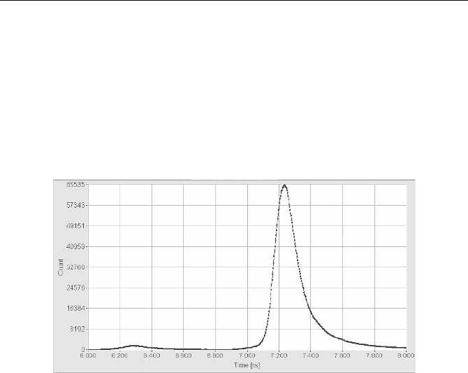
Fig. 6.20 Prepulses in a H5773P01 photosensor module can cause a bump about 1 ns
before the main peak of the IRF. The prepulses have a lower amplitude than the regular
pulses and can be suppressed by increasing the CFD threshold. Time scale 200 ps/div
Similar effects can arise from an inappropriate zero cross level in a CFD. If the
zero cross level is too close to the signal baseline, the zero cross comparator may
oscillate and produce a double structure in the IRF. Therefore the CFD parameters
should be checked before a PMT is suspected of producing prepulses.
In general prepulses do not cause major problems in TCSPC measurements.
Even if the corresponding peak in the instrument response function (IRF) cannot
be suppressed, e.g. because maximum counting efficiency is required, the decon-
volution with the actual IRF delivers correct results.
6.3 Measurement of PMT Parameters
6.3.1 Single Electron Response
The single-electron response (SER) of a PMT can be measured under weak con-
tinuous illumination by a fast oscilloscope. The input impedance of the oscillo-
scope must be switched to 50
:. A very fast oscilloscope must be used to obtain a
reasonable result, and precautions should be taken to avoid damaging the PMT or
the oscilloscope input circuitry (see Sect. 7.6, page 315).
6.3 Measurement of PMT Parameters 235
The width of the SER of conventional PMTs is of the order of a few ns. It can
be shorter than 0.5 ns for MCP PMTs. The leading edge has a rise time of 1 or
2 ns and 200 ps, respectively. Therefore the bandwidth of the oscilloscope must be
500 MHz to show the pulses at all and more than 1 GHz to display the leading
edge correctly. Moreover, an oscilloscope has no constant fraction discriminator
and shows pulses of different amplitude slightly shifted in time. The „Average“
function of a digital oscilloscope should therefore not be used, since the trigger
uncertainty caused by the amplitude fluctuation distorts the pulse shape.
The pulse amplitude is usually high enough to be recorded directly by the oscil-
loscope. Nevertheless, the use of a preamplifier is recommended to protect the
oscilloscope input against possible high-amplitude pulses. Such pulses can be
caused by cable discharge, scintillation effects or tiny electrical discharges in the
vicinity of the photocathode (Fig. 6.19, page 233). Moreover, a preamplifier with
current sensing gives a warning when the PMT output current becomes too high
(see Sect. 7.2.15, page 300).
The trigger uncertainty caused by amplitude jitter can be avoided by using short
laser pulses for testing. The oscilloscope is triggered by the laser and a large num-
ber of pulses is averaged. This requires that a photon must be detected in almost
every laser period. To avoid overloading the PMT, the pulse repetition rate must
be in the kHz range. The result of this measurement is the complete impulse re-
sponse of the PMT, i.e. the convolution of the SER and the TTS. Note that the low
repetition rate increases the risk of damaging the preamplifier or the oscilloscope;
if the laser intensity is too high, PMTs can deliver enormous pulse currents. The
peak amplitude for linear focused PMTs, such as the XP2020, can be up to 1 A.
Even miniature PMTs, such as the R5600 or R7400, deliver up to 200 mA.
The SER of a PMT can also be recorded by splitting the signal and triggering
the oscilloscope externally via a CFD. It is then possible to use a sampling oscillo-
scope or a fast boxcar device to record the pulse shape. There is, however, no
reason why a normal TCSPC user should take such effort to record an SER pulse
shape.
Some typical SER pulse shapes measured by a 500 MHz oscilloscope under
continuous illumination are shown in Fig. 6.21.
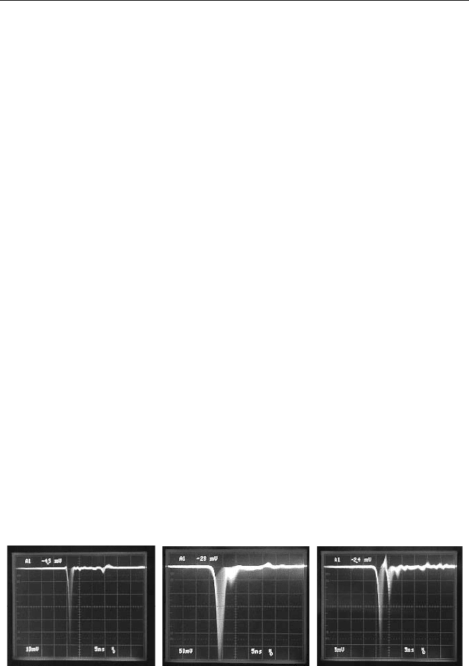
Fig. 6.21 SER pulses recorded by a 500 MHz oscilloscope. Left R5600 at 980 V, centre
XP2020UR at 2,500 V, right R931 at 980 V
The Hamamatsu R5600 miniature PMT (shown left) has a remarkably short and
clean SER. The average amplitude is about 20 mV, so that a preamplifier is re-
quired for TCSPC application.

236 6 Detectors for Photon Counting
The XP2020UR (shown in the middle) has a wider SER and a slower leading
edge. Although the operating voltage is far below the permissible maximum, the
average pulse amplitude is more than 100 mV. At first glance the high pulse am-
plitude may be considered a benefit. In practice, the high amplitude in conjunction
with the broad SER is rather a drawback, because it leads to a high average output
current at a given count rate. The high output current distorts the dynode voltage
distribution at high count rates, which in turn causes the TCSPC instrument re-
sponse to be count-rate-dependent; see Fig. 7.33, page 296.
The SER of an R931 side-window PMT is shown in Fig. 6.21, right. Side-
window PMTs were not originally designed for fast detection, and a large amount
of ringing is present in the SER. However, the somewhat ugly SER pulse shape
has no negative effect on TCSPC applications. Although the ringing may trigger
the CFD several times, this happens within the dead time of the TCSPC module
and is therefore not recorded. The situation is different for fast multichannel
scalers with a dead time of the order of 1 ns. If the time-channel width is of the
order of 1 ns, the ringing shows up in the IRF. Even if the time-channels are wider
than 1 ns, multiple counting of the larger pulses makes it impossible to obtain a
clear counting plateau by adjusting the discriminator threshold.
6.3.2 Transit Time Spread
The transit time spread is measured by illuminating the PMT cathode with short
light pulses and recording the pulse density versus time in a normal TCSPC setup.
The setup is the same as for recording of the instrument response function (IRF) of
a TCSPC system, and the same precautions should be taken to avoid broadening
of the measured response (see Sect. 5.1.6, page 75). Sufficiently short pulses have
to be used, and any optical elements that can cause pulse dispersion must be re-
moved. Monochromators, optical fibres, diffusers or scattering solutions must be
strictly avoided. The light of the test laser should be sent directly to the cathode of
the PMT through a set of neutral density filters. The stop pulse for the TCSPC
module should be delayed so that the same laser pulse that caused a photon also
stops the TAC. The count rate must be kept low enough to avoid pile-up. The
CFD threshold should be set to detect at least 20% of the detector pulses to avoid
distortion by multiphoton events (see Fig. 7.62, page 320).
A frequent source of failure in TTS measurements is improper shielding of the
detector. RF noise pickup from the environment or line frequency pickup via
ground loops can severely impair the timing accuracy of the TCSPC electronics. It
is obvious that the correct TTS cannot be measured under such conditions.
The TTS of conventional PMTs and miniature PMTs with metal channel dyn-
odes can be measured with satisfactory accuracy using picosecond diode lasers.
These lasers deliver pulses as short as 30 to 50 ps FWHM. However, the pulses
may have a tail or a shoulder, especially at higher power. The diode driving condi-
tions for clean pulse shape with minimum tail are usually not the same as for
shortest FWHM. The TTS of MCP PMTs can be reasonably measured only by a
Ti:Sapphire laser or a similar femtosecond or picosecond laser system.

6.3 Measurement of PMT Parameters 237
The transit-time distribution of most PMTs depends on the illuminated area and
on the voltage at the focusing electrodes. TTS shapes for a number of PMTs are
shown in chapter Sect. 6.4, page 242.
The measured TTS functions also depend on the CFD threshold and CFD zero
cross level used. One reason may be the normal degradation of the CFD timing
performance at low pulse amplitudes. Another reason is noise, which impairs
principally the timing of small-amplitude pulses. Irregular pulses may also be
caused by photoelectron emission from the first dynode or by elastically scattered
electrons at the first dynode.
The influence of the CFD parameters on the measured TTS is much more pro-
nounced for linear focused PMTs than for miniature metal channel PMTs and
MCPs. It is not clear whether this strong dependence is caused by imperfect zero-
cross timing in the CFD or slightly different SER pulse shapes for different elec-
tron trajectories in the PMT. It is therefore recommended to run a sequence of
recordings for different CFD threshold and zero cross level. In advanced TCSPC
devices, the sequential recording modes can be used to record such sequences
automatically. Examples for an XP2020UR are shown in Fig. 7.61, page 319, and
Fig. 7.63, page 321.
6.3.3 Pulse Amplitude Distribution
The usual way to measure the distribution of the SER pulse amplitude is by illu-
minating the PMT with weak light and recording a histogram of the pulse ampli-
tudes using a multichannel analyser (MCA). However, a normal multichannel
analyser is usually not able to record the small and short single-electron pulses of
a PMT directly. Therefore an amplifier with selectable gain and bandwidth must
be used in front of the MCA. In this setup, low-pass filtering in the amplifier is
used to broaden the single-photon pulses to a width that can be recorded by the
MCA, normally a few hundred ns to one microsecond. The low-pass filtering
causes a considerable loss in amplitude which must be compensated for by the
amplifier gain. The gain is adjusted that the amplitude of the amplified and broad-
ened pulses matches the input voltage range of the MCA. A total gain of the order
of 1,000 can be required.
The amplifier gain can be reduced by using a PMT load resistance or amplifier
input impedance of more than 50
:. The increased load resistor in conjunction
with the cable capacitance results in a pulse broadening without loss in amplitude.
Load resistors of the order of 1 k
: can be used. To avoid baseline drift in the
amplifier, AC coupling is used. The coupling constant is selected as to minimise
the baseline walk at higher pulse rates. Nevertheless, pile-up in the amplifier limits
the useful pulse rate to typically a few 10 kHz . The general measurement setup is
shown in Fig. 6.22.
238 6 Detectors for Photon Counting
Lamp
Filter
PMT
Low Pass
High Pass
MCA
Filter Filter
Fig. 6.22 Measurement of the SER pulse height distribution of a PMT by a multichannel
analyser
Due to the high gain in the measurement setup, good detector shielding is man-
datory. Although high-frequency noise and line-frequency pickup are suppressed
by the filters, the slightest pickup of radio frequency in the range from 100 kHz to
10 MHz can make the results useless.
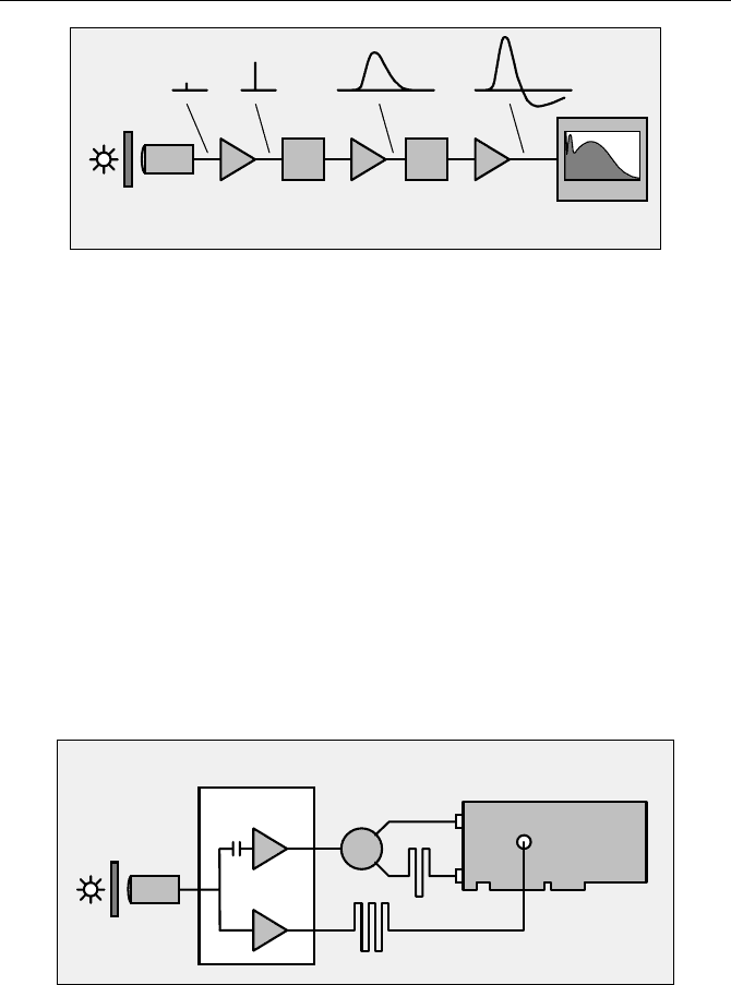
Single-board TCSPC modules usually do not give the user direct access to the
input of their internal MCA. If an input to the MCA is provided or can be made
available, the pulse height distribution can be recorded as shown in Fig. 6.23.
In the preamplifier, the PMT signal is split into a high-frequency and a low-
frequency component. (Such preamplifiers exist for microscopy applications.) The
high-frequency component is used to trigger both the start and stop input of the
TCSPC card. The stop input is delayed by a few ns to achieve normal start-stop
operation. The slow signal component is sent through a delay cable and fed into
the input of the biased amplifier of the TCSPC card. The cable length is adjusted
so that the pulse maximum is reached when the ADC of the TCSPC module sam-
ples the signal from the biased amplifier.
Lamp
Filter
PMT
Preamplifier for TCSPC
Power
Splitter
start
stop
Delay, 5ns
1 MHz
to 1 GHz
0 to 1 MHz
Delay, 50ns
Input of
biased
amplifier
scanning microscope
TCSPC card
Fig. 6.23 Recording of a pulse height distribution by a TCSPC module
Because of the high speed of the biased amplifier and the ADC in a TCSPC
board, the photon pulses delivered to the ADC need not be broader than 50 to
100 ns. Therefore an extremely high preamplifier gain is not required, and AC
coupling can be avoided. The setup can therefore be used up to a count rate of
several 10
5
pulses per second. Examples for pulse height distributions recorded
this way are shown in Fig. 6.13, page 227.
6.3 Measurement of PMT Parameters 239
Of course, the setup shown in Fig. 6.23 works only with a TCSPC module that
uses the TAC/ADC principle. Modules with direct time-to digital conversion do
not have an internal MCA and are therefore unable to record a pulse height distri-
bution in the way shown above.
Another possibility to record a pulse height distribution in a TCSPC system is
to run a CFD threshold scan. Starting from the lowest possible value, the CFD
threshold is gradually increased and the number of photons recorded in a given
time interval is recorded versus the CFD threshold. An example for an H5773
20
photosensor module is shown in Fig. 6.24.
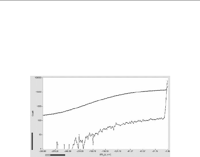
Fig. 6.24 CFD threshold scan for an H577320 photosensor module. Gain control voltage
0.9 V, preamplifier 20 dB. Upper curve recorded at 100,000 counts per second, lower curve
recorded with dark counts
Of course, threshold scanning records the integral of the pulse height distribution.
Differentiating the recorded curve results in a considerable increase of noise.
Moreover, the acquisition time is longer than for the MCA technique, and this can
be inconvenient, especially if the distribution of the dark pulses is to be recorded.
Nevertheless, threshold scanning has its benefits. If the PMT is illuminated with
laser pulses of high repetition rate, individual pulse height distributions for differ-
ent parts of the TTS can be obtained.
6.3.4 Afterpulsing Probability
Afterpulses of PMTs are difficult to detect in a standard TCSPC setup. The after-
pulses appear within a few microseconds after the detection of a photon. However,
TCSPC records only one detector pulse per signal period. An afterpulse is
recorded only if it appears in a new signal period and after the dead time caused
by the previously detected photon. Afterpulsing then shows up as a signal-
dependent background (see Fig. 7.31, page 294).
The afterpulsing probability can be measured by illuminating the detector by a
source of continuous classic light, such as an incandescent lamp or an LED, and
recording the detector pulses in the FIFO (time-tag) mode of a TCSPC module.
240 6 Detectors for Photon Counting
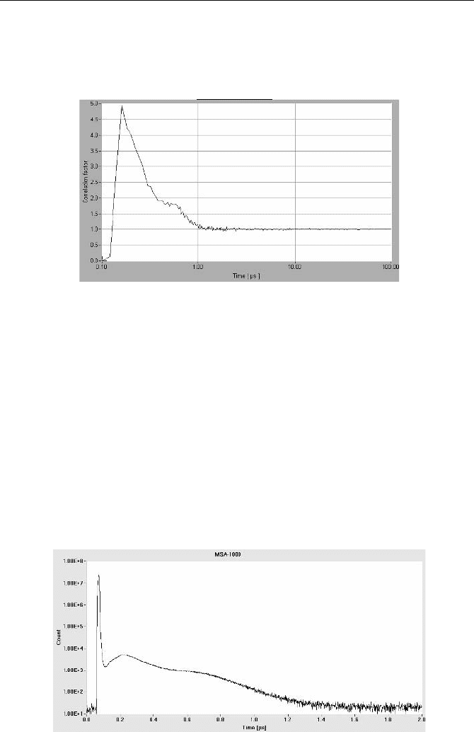
Afterpulsing reveals itself in the autocorrelation function of the photon density
over time. For continuous classic light, the autocorrelation function is a horizontal
line. Afterpulsing shows up as a peak at times shorter than a few microseconds.
An example is shown in Fig. 6.25.
Fig. 6.25 Afterpulsing of an R5600P1 PMT. Autocorrelation of the photon density re-
corded for a continuous light. Count rate 10,000 /s
The height of the afterpulsing peak depends on the count rate. The reason is
that the probability of detecting the afterpulse of a previously detected photon is
constant, whereas the probability of detecting another photon increases with the
count rate. To make the results directly comparable different detectors must be
tested at the same count rate.
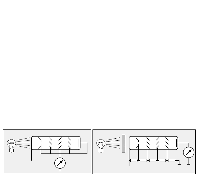
The density of the afterpulses, as a function of time after a light pulse, can be
recorded directly with a multichannel scaler. The PMT is illuminated with light
pulses at a pulse period in the µs range, and the PMT pulses are recorded over a
time interval of a few microseconds. An example for the same R5600
1 PMT is
shown in Fig. 6.26. An MSA
1000 multiscaler card (Becker & Hickl, Berlin) with
1 ns channel width was used. The afterpulsing is clearly seen as a long shoulder in
the recording of the light pulse.
Fig. 6.26 Afterpulsing of an R5600P1 PMT. Response to a 20 ns laser diode pulse, re-
corded by a 1 GHz multiscaler card, 200 ns/div
6.3 Measurement of PMT Parameters 241
6.3.5 Luminous Sensitivity and Quantum Efficiency
The radiant sensitivity of a detector – or its quantum efficiency – is one of the
most important parameters for TCSPC application. Unfortunately absolute meas-
urements of the radiant sensitivity or the quantum efficiency are extremely diffi-
cult. The problem is not only that a calibrated light source or a calibrated reference
detector are required but also that extremely low light intensities have to be used.
However, accurate attenuation of light by many orders of magnitude is difficult.
The „Cathode Luminous Sensitivity“ of a PMT is measured by using a tungsten
lamp operated at a temperature of 2,856 K. The PMT is used as a photocell; i.e. all
focusing electrodes, dynodes, and the anode are connected in parallel and used as
an anode (Fig. 6.27, left). A voltage of 100 to 200 V is applied between the cath-
ode and the other electrodes, and the photocurrent is measured. To avoid errors
due to the resistance of the photocathode, the current is kept in the µA or even nA
range. The advantage of the method is that the light intensity can be relatively
high. Calibrated lamps are available, and the intensity can be varied by changing
the distance of the lamp from the PMT.
-HV
Current
Lamp Filter
PMT
-100V Current
Lamp
PMT
Fig. 6.27 Measurement of the Cathode Luminous Sensitivity (left) and the Anode Lumi-
nous Sensitivity (right)
The „Anode Luminous Sensitivity“ is measured in a similar setup as the Cath-
ode Luminous Sensitivity. However, the PMT is operated in the normal way, i.e.
by applying the specified voltage distribution to the dynode chain (Fig. 6.27,
right). Of course, a calibrated filter has to be inserted in the light path to attenuate
the light of the lamp to a level that does not overload the PMT. As mentioned
before, the anode luminous sensitivity is not very useful in characterising a PMT
for TCSPC.
The „Cathode Radiant Sensitivity“ is the current of the photocathode divided
by the power of the incident light at a given wavelength. Measuring the Cathode
Radiant Sensitivity requires a lamp, a monochromator and a reference detector,
e.g. a calibrated photodiode. The setup is difficult to calibrate due to the various
error sources.
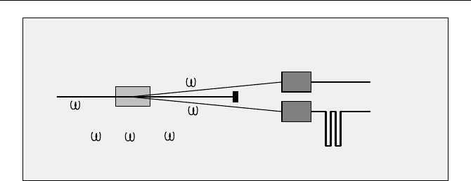
A technique for measuring the quantum efficiency of a photon counting detec-
tor without a calibrated reference detector is described in [301, 356, 357, 358, 423,
536]. The technique is based on the generation of photon pairs – or „entangled
photons“ - by parametric down-conversion. The principle is shown in Fig. 6.28.
242 6 Detectors for Photon Counting
Start
Stop
TCSPC
KDP Crystal
Pump Beam
Detector
Reference
under Test
Detector
Beam
Dump
p
1
2
p
2
1
=
+
Fig. 6.28 Absolute measurement of the detector quantum efficiency by parametric down-
conversion
A NUV laser pumps a KDP (potassium dihydrogen phosphate) crystal. Down-
conversion in the crystal generates photon pairs with a total energy equal to the
energy of the pump photons. The photons of a pair are emitted in slightly different
directions and can therefore be separated spatially. One photon is sent to the detec-
tor being tested, the other photon to a timing reference detector. A photon pulse
from the reference detector indicates that a photon pair has been produced. The
quantum efficiency of the detector being tested is the probability that it detects the
other photon of the pair. The result does not depend on the efficiency of the refer-
ence detector.
The scattered pump light is blocked by interference filters in front of the detec-
tors. These filters are the only parts of the system that need calibration. Because
the transmission is in the 10 to 90% range, a highly accurate calibration is possi-
ble. Errors due to detector background and possible filter leakage are avoided by
using the pulses of the detectors as the start and stop of a TCSPC device. The
result is a coincidence curve that can be clearly separated from uncorrelated back-
ground signals.
A TCSPC user normally has to be content with comparisons between different
detectors. If detectors are compared in terms of efficiency, it must be taken into
account that the detectors may require different gain and discriminator thresholds
for optimal efficiency and timing performance. Moreover, different sizes of the
active area or different longitudinal positions of the photocathodes may require
different relay optics. LEDs are convenient light sources for efficiency tests be-
cause the intensity of an LED can be controlled in a wide range by changing the
current, and remains stable as long as the temperature does not change.
6.4 Photon Counting Performance of Selected Detectors
This section gives an overview of the TCSPC performance of a number of detec-
tors frequently used in TCSPC applications [243]. All IRFs shown below were
measured under real-world conditions with TCSPC modules from Becker & Hickl.
The IRFs were recorded with combinations of detector gain and CFD threshold
6.4 Photon Counting Performance of Selected Detectors 243
resulting in operation at a high level of counting efficiency, i.e. with no more than
20% of the pulses rejected.
Autocorrelation functions of the photon pulse density measured with continu-
ous light are given for most of the detectors. The curves are normalised. A correla-
tion coefficient of 1 means the detected pulses are not correlated, i.e. no after-
pulses are detected. A correlation coefficient greater than one indicates correlation
of the pulses, i.e. afterpulsing; the autocorrelation functions reflect the afterpulse
density versus time. The curves give a direct impression of the performance of the
detectors in FCS applications. Indirectly, the amount of afterpulsing is related to
the signal-dependent background in high-repetition rate fluorescence decay or
DOT applications. The effect of afterpulsing on the autocorrelation function de-
pends on the count rate (see Fig. 5.117, page 185). To make the autocorrelation
curves comparable, the data for all detectors were recorded at a count rate of
10 kHz.
The results given below are believed to be representative of the particular de-
tectors or groups of detectors described. However, detector parameters may vary
for different specimens of the same type, and will depend on possible changes in
the manufacturing process. This is especially the case with parameters that depend
on the gain, such as maximum count rate and afterpulsing probability.
6.4.1 MCP-PMTs
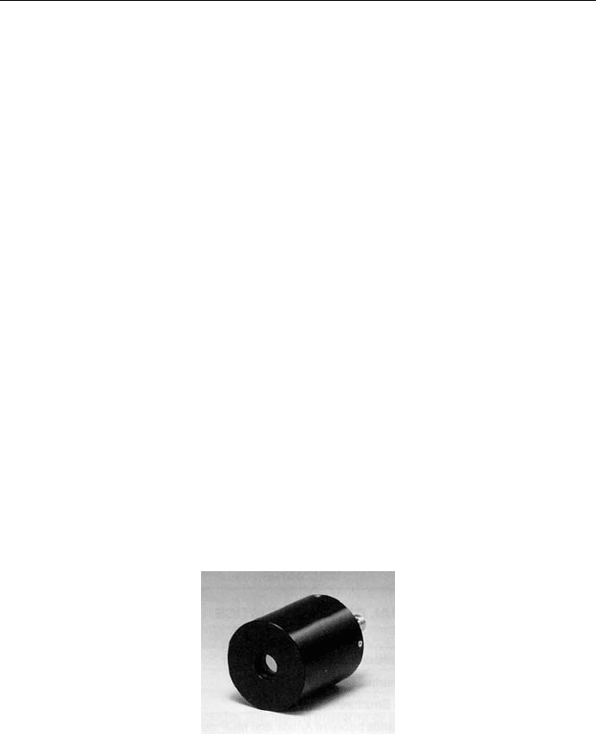
MCP-PMTs [298] are currently the fastest commercially available detectors for
TCSPC. A typical representative of this detector type, the Hamamatsu R3809U
[211], is described below. The detector is shown in Fig. 6.29.
Fig. 6.29 Hamamatsu R3809U MCP-PMT [211]
The TCSPC system response measured for a R3809U50 MCP is shown in
Fig. 6.30. The R3809U was illuminated with a femtosecond Ti:Sapphire laser
through a package of ND filters, and the response was measured with an SPC
630
TCSPC module. A 20 dB, 1.6 GHz preamplifier was used in front of the CFD
input. At an operating voltage of –3 kV, the FWHM (full width at half maximum)
of the response is 28 ps. The width of the response can be reduced to 25 ps by
increasing the operating voltage to the maximum permitted value of –3.4 kV.