Biringen S., Chow C.-Y. An Introduction to Computational Fluid Mechanics by Example
Подождите немного. Документ загружается.

72 INVISCID FLUID FLOWS
expression (2.5.6),
ψ(r
i
, z
i
) =
1
2
Ur
2
i
+
n
j=1
q
j
r
2
i
+
z
i
−z
j+1
2
−
r
2
i
+
z
i
−z
j
2
(2.5.7)
The left-hand side of the above equation is zero because the point P
i
is on the
body surface. And, from Fig. 2.5.2, the two terms contained within the brackets in
(2.5.7) represent the two distances d
i, j +1
and d
ij
, measured respectively from the
surface point P
i
to the end points P
j+1
and P
j
of segment j. With the notation that
d
ij
= d
ij
−d
i, j +1
=
r
2
i
+
z
i
−z
j
2
−
r
2
i
+
z
i
−z
j+1
2
(2.5.8)
and after replacing q
j
/U by Q
j
, (2.5.7) becomes
n
j=1
d
ij
Q
j
=
1
2
r
2
i
(2.5.9)
in which all quantities but the Q
j
’s are known for specified locations of both
the source segments and surface points.
Since Q is proportional to the volume of fluid produced per unit time from
sources within a unit length of a segment, it requires that the total strength of
the sources or sinks must be zero in order to form a closed body. That is,
n
j=1
s
j
Q
j
= 0 (2.5.10)
Combining the n − 1 equations obtained by evaluating (2.5.9) at all surface
points and the equation (2.5.10), we have a complete set of n simultaneous
algebraic equations for the unknown source strengths:
⎡
⎢
⎢
⎢
⎢
⎢
⎣
d
11
d
12
··· d
1n
d
21
d
22
··· d
2n
.
.
.
.
.
. ···
.
.
.
d
n−1,1
d
n−1,2
··· d
n−1,n
s
1
s
2
··· s
n
⎤
⎥
⎥
⎥
⎥
⎥
⎦
⎛
⎜
⎜
⎜
⎜
⎜
⎝
Q
1
Q
2
.
.
.
Q
n−1
Q
n
⎞
⎟
⎟
⎟
⎟
⎟
⎠
=
⎛
⎜
⎜
⎜
⎜
⎜
⎜
⎜
⎝
r
2
1
/2
r
2
2
/2
.
.
.
r
2
n−1
/2
0
⎞
⎟
⎟
⎟
⎟
⎟
⎟
⎟
⎠
(2.5.11)
Once Q
j
’s are known, the stream function expressed by (2.5.6) becomes deter-
mined. According to (2.5.1), the corresponding velocity components are
u
r
=−
n
j=1
UQ
j
r
⎡
⎢
⎢
⎣
z − z
j+1
r
2
+
z − z
j+1
2
−
z − z
j
r
2
+
z − z
j
2
⎤
⎥
⎥
⎦
(2.5.12)
VON K
´
ARM
´
AN’S METHOD FOR APPROXIMATING FLOW PAST BODIES OF REVOLUTION 73
u
z
= U
⎧
⎪
⎪
⎨
⎪
⎪
⎩
1 +
n
j=1
Q
j
⎡
⎢
⎢
⎣
1
r
2
+
z − z
j+1
2
−
1
r
2
+
z − z
j
2
⎤
⎥
⎥
⎦
⎫
⎪
⎪
⎬
⎪
⎪
⎭
(2.5.13)
They show that the velocities induced by the source distributions are diminishing
far away from the body.
The pressure field can be computed from the Bernoulli equation (2.1.7) with
the nonsteady term dropped. If P is used to denote the pressure far away from
the body, the Bernoulli constant can be evaluated, and (2.1.7) becomes
p +
1
2
ρ(u
2
r
+u
2
z
) = P +
1
2
ρU
2
Instead of the pressure, it is sometimes more convenient to use the dimensionless
pressure coefficient c
p
, defined as the excess pressure over the free-stream value
divided by the free-stream dynamic pressure. Thus,
c
p
=
p −P
1
2
ρU
2
= 1 −
u
r
U
2
−
u
z
U
2
(2.5.14)
and its value at any point can be computed after substitution of the velocity
components at that point obtained from (2.5.12) and (2.5.13).
The solution of (2.5.11) can be obtained by Gaussian elimination or by finding
the inverse of the coefficient matrix. Defining d as the coefficient matrix, Q as
the vector of unknowns, and r as the right-hand-side vector, the latter method
can be written as
dQ = r (2.5.15)
d
−1
dQ = d
−1
r (2.5.16)
with d
−1
d = I (identity matrix),
Q = d
−1
r (2.5.17)
In Program 2.3, the inverse matrix is calculated by MATLAB function inv(d).
To test the accuracy of von K
´
arm
´
an’s method, it will be applied to a problem
having a known solution. Such a problem can be formed by adding a uniform flow
to a point doublet, described respectively by (2.5.3) and (2.5.5). By assigning the
value Ua
3
/2 to the strength μ of the doublet, the stream function of the combined
flow becomes
ψ =
1
2
Ur
2
1 −
a
3
R
3
(2.5.18)
where R(=
√
r
2
+z
2
) is the radial distance from the origin. This shows that the
streamline (actually the stream surface) ψ = 0 consists of the z axis, along which
r = 0, and the surface of a sphere of radius a. It can be verified, with the help
74 INVISCID FLUID FLOWS
of (2.5.1), that the magnitude of the velocity at a point (r, z) on the sphere is
|V|=
3
2
U
r
a
(2.5.19)
The pressure coefficient at that point is, according to (2.5.14),
c
p
= 1 −
9
4
r
a
2
(2.5.20)
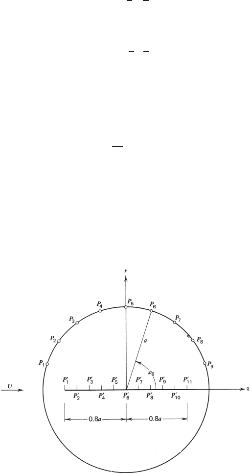
For the numerical scheme of Program 2.3, sources are distributed within
ten segments of equal lengths on the z-axis between z =±0.8a, and nine
equally spaced points are chosen on the upper surface of the sphere, as shown
in Fig. 2.5.3. If ϕ
i
denotes the angle between the z-axis and the radial position
of the surface point P
i
(r
i
, z
i
), the nine values of ϕ
i
are
ϕ
i
= (10 −i)
π
10
, i = 1, 2, ..., 9 (2.5.21)
from which the coordinates are computed through the relationships
r
i
= a sin ϕ
i
and z
i
= a cos ϕ
i
(2.5.22)
After the source strengths are determined, the velocities and pressure coefficients
at the surface points will be calculated and compared with the exact values
represented by (2.5.19) and (2.5.20).
FIGURE 2.5.3 Source segments and surface points used in Program 2.3.
VON K
´
ARM
´
AN’S METHOD FOR APPROXIMATING FLOW PAST BODIES OF REVOLUTION 75
It is more convenient to nondimensionalize length and velocity by using the
characteristic quantities a and U , respectively. This is achieved by letting a = 1
and U = 1 in Program 2.3.
The output of Program 2.3 shows that the velocity and pressure coefficient
obtained by using von K
´
arm
´
an’s method are almost identical to those computed
from the exact solution, except at a few points where discrepancies appear at the
fourth decimal place. In von K
´
arm
´
an’s original work (1927) the body of a ZR III
dirigible was generated in a uniform flow by using a group of sources near the
bow and a separate group of sinks near the stern. The tacit assumption was that the
contributions of the bow sources to the pressure distribution over the aft section
and that of the stern sinks over the forward section would be negligible. The
calculated pressure coefficient was in good agreement with the measured pressure
coefficient without counting the discrepancy in the neighborhood of the gondola.
Program 2.3 can be modified to compute the flow around a body of revolution of
any shape. The user needs only to re-specify the positions of both source segments
and surface points and to change the affected statements if the number of source
segments is different from 10, the number presently used in that program.
Problem 2.4 It works as well if the source segments of Fig. 2.5.2 are replaced
by discrete point sources of unknown strengths. Write a program for this purpose
and use it to solve the sphere problem stated in Program 2.3.
Project for Further Study: Extend von Karman’s method to solve the prob-
lem of uniform flow past a two-dimensional closed body of arbitrary shape,
which is symmetric about its centerline parallel to the oncoming flow. In this
case line sources and sinks described by (2.4.2) will be distributed within small
intervals along the centerline. In the evaluation of the integral over a source seg-
ment to find the stream function at a point, it is easier to replace the integrand
tan
−1
[(y − y
0
)/(x −x
0
)]bycot
−1
[(x −x
0
)/(y − y
0
)]. After a procedure has been
developed for the numerical computation, it is to be applied to calculate the fluid
speed, V , and pressure coefficient, c
p
, on the surface of a two-dimensional wing
at zero angle of attack, whose cross section is a symmetric NACA 0009 air-
foil. The shapes and characteristics of this and many other airfoils designated by
the National Advisory Committee for Aeronautics are described in the book by
Abbott and von Doenhoff (1949). The following table shows the dimensionless
coordinates of some selected points on the airfoil and the dimensionless speeds
there, in which c is the chord length of the wing and U is the free-stream speed
in the x direction.
x/c 0 0.050 0.100 0.200 0.300 0.400 0.500 0.600 0.700 0.800 0.900 1.000
y/c 0 0.027 0.035 0.043 0.045 0.044 0.040 0.034 0.027 0.020 0.011 0
V /U 0 1.140 1.144 1.137 1.119 1.100 1.082 1.061 1.043 1.018 0.982 0
The tabulated values of V
/
U , obtained by employing a different method, are
included for comparison with the numerical result.
76 INVISCID FLUID FLOWS
2.6 INVERSE METHOD II: CONFORMAL MAPPING
In considering steady two-dimensional potential flows in Section 2.1, it was
shown that the velocity components could be derived from either the velocity
potential or the stream function, both of which satisfy the Laplace equation. The
relationships involved there are repeated as follows:
u =
∂φ
∂x
=
∂ψ
∂y
(2.6.1)
v =
∂φ
∂y
=−
∂ψ
∂x
(2.6.2)
∂
2
φ
∂x
2
+
∂
2
φ
∂y
2
= 0 (2.6.3)
∂
2
ψ
∂x
2
+
∂
2
ψ
∂y
2
= 0 (2.6.4)
The φ = constant and ψ = constant curves are called, respectively, the equipo-
tential lines and the streamlines of the flow. At a point where an equipotential
line intersects a streamline, the vectors that are respectively normal to the two
curves are perpendicular to each other, since
∇φ · ∇ψ =
∂φ
∂x
∂ψ
∂x
+
∂φ
∂y
∂ψ
∂y
= (u)(−v) +(u)(v) = 0
Thus, the equipotential lines and the streamlines of a two-dimensional flow form
two families of mutually orthogonal curves in the x-y plane, except at stagnation
points where the directions of the normal vectors are not defined.
We now introduce a complex variable, z = x +iy,wherei =
√
−1 is called
the imaginary unit, and construct with velocity potential and stream function a
complex function
w(z) = φ(x, y) +iψ(x, y) (2.6.5)
If w is a single-valued function of z , as assumed in the above form, and if its
derivative of the first order, dw/dz, exists throughout the region occupied by the
fluid, then the derivative at any point in that region can be computed regardless
of the way in which the increment in z tends to zero. Let z = x +iy be
such an increment. To find the derivative we may choose to let y equal zero
and then let x approach zero (see Churchill, 1948, Section 18). By choosing
INVERSE METHOD II: CONFORMAL MAPPING 77
such a path, z = x and
dw
dz
= lim
x→0
φ(x +x, y) −φ(x, y) +iψ(x +x, y) − iψ(x, y)
x
=
∂φ
∂x
+i
∂ψ
∂x
(2.6.6)
Alternatively, we may choose to let x equal zero and then let y approach
zero. Thus, z = iy and
dw
dz
= lim
y→0
φ(x, y + y) −φ(x, y) +iψ(x, y +y) − iψ(x, y)
iy
=−i
∂φ
∂y
+
∂ψ
∂y
(2.6.7)
Equating the right-hand members of (2.6.6) and (2.6.7) results in
∂φ
∂x
=
∂ψ
∂y
and
∂φ
∂y
=−
∂ψ
∂x
(2.6.8)
These equations are called the Cauchy-Riemann conditions, which are the neces-
sary conditions for the existence of the derivative of the function w(z).Butthese
conditions are satisfied automatically by (2.6.1) and (2.6.2) derived for a potential
flow. This means that φ +iψ, the function on the right-hand side of (2.6.5), is an
analytic function of z , that is, a function that is differentiable for the values of z
in a region of the z plane. If a function is analytic in the neighborhood of a point
but not at the point itself, this point is called a singular point, or a singularity,
of that function. Furthermore, (2.6.3) and (2.6.4) are obtained after eliminating
either φ or ψ from the Cauchy-Riemann conditions (2.6.8), indicating that both
real and imaginary parts of an analytic function satisfy the Laplace equation.
Conversely, if we choose an arbitrary analytic function w(z), the real and
imaginary parts of the function then automatically qualify as the velocity potential
and the stream function, respectively, of a potential flow in the x-y plane. The
function w shown in (2.6.5) is called the complex potential, whose derivative
is related to the velocity components through the following relationship, derived
from either (2.6.6) or (2.6.7):
dw
dz
= u − iv (2.6.9)
Hence, the magnitude of the velocity vector is obtained by taking the absolute
value of the above expression.
As an example, let us consider a simple analytic function
w(z) = Uze
−iα
(2.6.10)
78 INVISCID FLUID FLOWS
in which U and α are constants. After being separated into real and imaginary
parts, (2.6.10) becomes
w = U (x cos α + y sin α) +iU (y cos α −x sin α)
The imaginary part is precisely the stream function of the uniform flow
described by (2.4.1) and Fig 2.4.1a. It follows that the real part represents
the velocity potential and the right side of (2.6.10) represents the complex
potential of that uniform flow. To find the fluid velocity components, we simply
use (2.6.9) to obtain u = U cos α and v = U sin α. It can also be shown in a
similar fashion that the functions (/2π)log(z − z
0
), (i/2π)log(z −z
0
),and
κ/2π(z − z
0
) are, respectively, the complex potentials of the source, vortex, and
doublet described by (2.4.2) to (2.4.4), where z
0
= x
0
+iy
0
.Eachofthesethree
functions has a singular point at z
0
, where the first derivative of the function (or
the velocity) is unbounded.
We have thus arrived at another inverse method, through which we can gener-
ate as many potential flows as we can write analytic functions. The principle of
superposition of elementary flows can still be applied in generating new flows.
For example, the sum of Uz, the complex potential of a uniform horizontal flow,
and κ/2π z, the complex potential of a doublet at the origin, represents the com-
plex potential of a uniform flow past a circular cylinder of radius
√
κ/2πU
centered at the origin.
There exists another powerful method, called the method of conformal map-
ping, that is used to generate new flow patterns by mapping a known flow in the
x-y plane into a new x
-y
plane through various transformations between the
two sets of coordinates. Suppose that the complex potential w(z) in (2.6.5) is
known for a given flow. Let the variable z
(= x
+iy
) be related to z through
the relationship
z = f (z
) (2.6.11)
where f is an analytic function of z
. Upon the use of (2.6.11), w becomes an
analytic function of z
because the derivative
dw
dz
=
dw
dz
df
dz
(2.6.12)
exists, due to the existence of the two derivatives on the right-hand side of
(2.6.12). After being transformed into the z
plane, the complex potential may be
grouped into real and imaginary parts according to the new coordinates, so that
w
f (z
)
= φ
(x
, y
) + iψ
(x
, y
) (2.6.13)
It follows from the properties of analytic functions that φ
and ψ
must satisfy
the Cauchy-Riemann conditions
∂
2
φ
∂x
2
+
∂
2
φ
∂y
2
= 0

INVERSE METHOD II: CONFORMAL MAPPING 79
∂
2
ψ
∂x
2
+
∂
2
ψ
∂y
2
= 0
Thus, the φ
= constant and ψ
= constant lines remain mutually orthogonal in
the x
-y
plane after the transformation, and (2.6.13) represents the complex
potential of a flow in the x
-y
plane.
Furthermore, because (2.6.5) and (2.6.13) represent the same complex func-
tion, we must have
φ(x, y) = φ
(x
, y
)
ψ(x, y) = ψ
(x
, y
)
except that some additive constants may appear in these equations. Hence, under
the transformation (2.6.11), a streamline ψ = c and a perpendicular equipotential
line φ = k in the x-y plane map, respectively, into a streamline ψ
= c and an
equipotential line φ
= k in the x
-y
plane. The two curves, although distorted in
shape, remain perpendicular to each other after the transformation. For this reason
the mapping is said to be conformal. Theorems related to conformal mapping and
their proofs are found in Chapter 8 of the book by Churchill (1948).
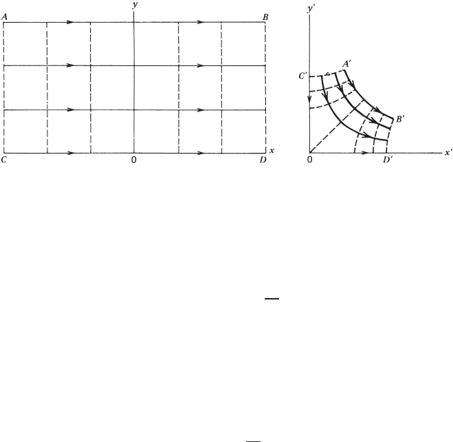
To illustrate the use of this method, we consider the complex potential
w(z) = Uz
= Ux + iUy (2.6.14)
of a uniform stream with speed U flowing along the positive x direction. By
choosing a specific form
z = z
2
(2.6.15)
for the transformation (2.6.11), the complex potential becomes
w(z
) = Uz
2
= U (x
2
−y
2
) +i2Ux
y
(2.6.16)
Thus, the streamlines y = c and the equipotential lines x = k in the x-y plane
are mapped into streamlines 2x
y
= c and equipotential lines x
2
-y
2
= k in the
x
-y
plane, as shown, respectively, by the solid and dashed lines in Fig. 2.6.1.
The pattern describes the flow past a 90
◦
corner.
In general, the function on the right side of (2.6.11) may be expanded in a
series of positive and negative powers of z
and, in this respect, the transformation
(2.6.15) is merely a special case of the series expansion. If two terms of the
following particular form are retained in the series, the relation
z = z
+
a
2
z
(2.6.17)
80 INVISCID FLUID FLOWS
FIGURE 2.6.1 Mapping of a uniform flow in the x-y plane into the x
-y
plane by the
transformation z = z
2
.
is called the Joukowski transformation. Under this transformation the complex
potential of a uniform flow, (2.6.14), becomes
w(z
) = U
z
+
a
2
z
(2.6.18)
which is the complex potential for a uniform flow past a circular cylinder of
radius a. The same result was obtained earlier by adding the complex potential
of a uniform flow to that of a doublet.
The Joukowski transformation is probably one of the most widely used trans-
formations in solving potential flow problems. For instance, the transformation
z = z
+
b
2
z
(2.6.19)
where b
2
< a
2
, maps a circle of radius a with center at the origin of the x
, y
coordinates into an ellipse in the x-y plane (Fig. 2.6.2). The same transformation
maps two circles intersecting the positive x
axis at x
= b, with the center of
one circle on the y
axis and that of the other off the coordinate axes, into a
circular arc and a so-called Joukowski airfoil in the x-y plane (Fig. 2.6.3). The
detailed description of these mappings can be found in Chapter 4 of Yih (1969).
Suppose that the flow about the elliptic cylinder of Fig. 2.6.2 is to be sought. A
relationship that expresses z
as a function of z may first be obtained by taking
the inverse of (2.6.19). Upon substitution of this relationship into the expres-
sion (2.6.18) for the complex potential of the flow about a circular cylinder, we
obtain the complex potential of the flow about the elliptic cylinder. Streamlines
can then be plotted by assigning various constant values to the stream function or
the imaginary part of the transformed complex potential. This procedure, how-
ever, involves tedious analytical work, especially when separating a complicated
function into real and imaginary parts. For this reason we will choose a different
approach by solving the problem numerically.
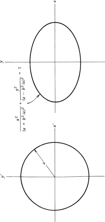
FIGURE 2.6.2 Mapping of a circle in the x
-y
plane into an ellipse in the x-y plane by the Joukowski transformation z = z
+b
2
/z
.
81