Bryant A.C. Refrigeration equipment
Подождите немного. Документ загружается.


50
Refrigeration Equipment
8 Set the suction service valve to the operating position and operate
the plant.
9 Reset the low pressure control to its original cut-out setting.
10 Remove gauges, fit service valve caps and carry out a final leak test.
11 Clear the site of debris etc.
Should the filter drier be completely blocked, which is improbable, then the
replacement procedure will be the same as that given earlier for the replace-
ment of a thermostatic expansion valve with a complete loss of charge.
The filter drier is described further in Chapter 12.
Low side purging
Low side purging is now considered to be bad practice and air in the system
should be removed by using a vacuum pump to minimize refigerant loss to
the atmosphere which in turn affects the ozone layer. The correct procedure
to be adopted is given in the section dealing with reclaim and recovery of
refrigerants.
Moisture in the system
When a system pipework is opened to atmosphere during a replacement oper-
ation, it is possible that air will enter the system. Air contains moisture,
and only a small amount of moisture in a system which has a capillary for
the refrigerant control can result in that moisture freezing. This leads to a
complete loss of refrigeration.
Filter driers are normally capable of dealing with small quantities of mois-
ture. However, it is recommended that a drier be changed when leaks are
detected, especially on the low side.
A complete loss of the refrigerant charge owing to leakage can result in a
compressor operating on vacuum, drawing in air. In this case the drier could
become saturated and moisture will circulate through it. When this occurs,
freezing can take place at the expansion valve; this is tantamount to a complete
blockage in the liquid line.
When the symptoms of plant operation indicate a complete blockage, and
no temperature difference is obvious at the filter drier, it is natural to suspect
that the expansion valve or perhaps a solenoid valve is at fault. The simple
expedient of applying a cloth dipped in hot water will determine the presence
of moisture. Warming up the expansion valve will melt the ice in the valve and
Service diagnosis and repairs 51
the flow of refrigerant will resume, but only until such time as the temperature
at the expansion valve is low enough to form ice and restrict the liquid flow
once more. A blowtorch should never be used for this purpose, for obvious
reasons.
In most cases, fitting a new filter drier will overcome the problem. However,
it is stressed that this drier should be removed after a suitable running period
and another new drier fitted. Should the condition persist after a drier has
been replaced, the system must be discharged of refrigerant, evacuated and
then recharged.
Compressor efficiency test
This is also referred to as a compressor pump test. It is carried out when the
functions of the compressor suction and discharge valves are suspect; this will
be indicated by high suction and low discharge pressures. The test should be
carried out with the plant running at an operating head pressure of at least
100 psig or 6.5 bar if possible in order to prove the efficiency of the valves.
The procedure is as follows:
1 Front seat the suction service valve and note the cut-out pressure of the low
pressure control.-The control must be reset to its original cut-out pressure
after the test.
2 Alter the range of the low pressure control so that the compressor is
drawing a vacuum.
3 Reduce the low side pressure to at least 20 in Hg vacuum or 0.7 bar.
4 Stop the compressor and observe the pressure rise on the compound gauge
for 2 minutes.
If the suction reeds are seating properly and cylinder/piston wear is not exces-
sive, the pull-down to a vacuum should be rapid. The front seating of the
suction service valve isolates pressure coming from the evaporator, and only
the compressor crankcase is being evacuated of the refrigerant vapour. A
compressor is deemed reasonably efficient if the 20 in vacuum is achieved.
If it is not possible to draw this vacuum, then the suction reeds are defective.
When a 20 in vacuum is achieved, the pressure rise should be minimal; the
entire vacuum should not be lost over the 2 minute observation period. When
the vacuum is drawn and the plant switched off, if a rapid rise in pressure
is observed on the compound gauge then refrigerant vapour is leaking into
the cylinder(s) via the discharge valve(s). The valves must be inspected for
distortion of reeds or faulty seating.
52
Refrigeration Equipment
Removing compressor valve plate assembly
On most compressors this will be a relatively simple task, but the proce-
dure will differ with compressor design. The following is the procedure for a
compressor with the valves in the head:
1 Start the plant, front seat the suction service valve and reduce the crankcase
pressure to 3 psig or 0.2 bar if possible.
2 Stop the plant, isolate electrically and front seat the discharge service valve.
3 Slacken off the compressor head bolts slowly to release the high pressure
from the discharge side of the head. Remove the bolts.
4 Gently raise the compressor head, with suction and discharge lines intact,
sufficiently high to be able to withdraw the valve plate assembly. Care
must be taken to avoid fracture of the pipework unions.
5 If the cylinder head and valve plate gaskets are damaged when the valve
plate is removed, they must be replaced.
6 Distorted or broken reeds will obviously have to be replaced. Some manu-
facturers will recommend replacement of the entire valve plate assembly;
replacement kits are available complete with gaskets.
Should the valve seats on the valve plate be eroded or pitted and a replace-
ment is not readily available, they can be made serviceable by reseating or
lapping. This is generally regarded as a workshop practice. The method is as
follows:
1 Obtain some valve grinding paste or carborundum powder and some
polishing compound. Spread a liberal amount of the paste on to a lapping
block or a hard flat surface such as a polished steel plate or sheet of glass.
2 Remove the discharge reed retainers and reeds from the valve plate.
3 Place the valve plate on the pasted surface, exert a firm even pressure and
move the valve plate in a figure-of-eight motion. Continue until the valve
seats are returned to an original finish. When carborundum powder is used
it should be mixed with refrigeration oil.
4 When reseating is complete, remove all traces of carborundum and paste
from the valve plate with spirit or paraffin.
5 Repeat the operation with the polishing compound and clean as before.
6 Reassemble dry with new reeds if required. If the original reeds are used,
they should be inverted so that the seat contact is made to the unused side
of the reed.
The procedure for replacing the valve plate assembly is as follows. If gaskets
are re-used they should be perfectly clean and dry.
Service diagnosis and repairs
53
1 Once the valve plate is located, replace the head bolts and screw them
down finger tight.
2 Tighten the bolts diagonally across the head, care being taken not to
overtighten and strip the threads.
3 Crack off the suction and discharge service valves from the front seat
positions.
4 Leak test the compressor and pipework unions.
5 Purge the compressor through the gauge port unions.
6 Set the service valves to the operating positions and start the plant.
7 Operate the plant and observe pressures; these should now be normal.
8 Carry out the compressor pump test.
9 Reset the low pressure control.
10 Remove gauges, replace valve seal caps and wipe the compressor clean
of oil.
11 Make a final leak test.
12 Clear the site.
Removing a compressor rotary shaft seal
Most smaller open drive and some direct drive semi-hermetic compressors
employ this type of crankshaft seal. They are often a cause of noise complaints
(squeaking) and refrigerant leaks. Generally this is due to lack of lubrication;
when the seal surfaces are dry, wear and scoring of the polished facings occur.
In order to remove this type of seal it is necessary first to remove the
compressor flywheel. The larger the compressor, the larger and heavier will
be the flywheel. Extra care must be exercised when removing the larger types,
which may be castings and easily damaged if dropped. Removal should not
be attempted without a suitable extractor. Under no circumstances should a
hammer be used to break the bond between shaft, keyway and flywheel boss
(not for semi-hermetic compressors).
Systems must be pumped down and isolated electrically. The drive belt
guards must be removed to gain access to the flywheel on units with water
cooled systems or with a remote condenser. On smaller air cooled units the
compressor must be removed from its base, and this is dealt with here.
Open drive units (valves in the head type)
Pump down the system, front seat both service valves and isolate the unit
electrically.
54
Refrigeration Equipment
2 Remove the head retaining bolts and gently raise the compressor head.
3 Withdraw the valve plate assembly and remove the suction reeds from
the cylinders.
4 Remove the compressor mounting bolts and belt guard.
5 Slide the compressor body towards the drive motor, release the drive belts
from the flywheel and remove the compressor body.
6 Release the locking device on the drive shaft. This could be in the form
of two locknuts, a locknut and a tab washer, or a locknut and a pin.
7 Using a suitable extractor, locate the arms around the flywheel boss (avoid
locating around the flywheel vee section). Never use a hammer to remove
a flywheel.
8 Apply gentle pressure on the extractor to break the bond, then remove
the flywheel. With large heavy types it is advisable to tie a rope or cord
to the flywheel and secure it in case the bond breaks suddenly.
9 Remove the seal plate retainer bolts and seal plate. The seal will be
released by spring pressure in most cases; withdraw the seal from the
seal housing.
l0 Remove the seal ring from the shaft.
It may be necessary to change the compressor oil when a seal replacement is
made, or some oil may be lost during replacement.
The procedure for replacement is as follows. Some manufacturers supply a
shaft centring tool to ensure that the seal is correctly aligned on the shaft; this
also eliminates uneven pressure being applied by the seal plate and spring
during assembly.
1 Locate the seal ring on to the shaft and push fully home to the shaft
shoulder.
2 Dip the seal nose in refrigeration oil and locate over the shaft, using the
centring tool if available.
3 Replace the seal plate, depressing evenly against the spring. Insert the
retaining bolts, and tighten the bolts so as to maintain the correct align-
ment of the shaft seal assembly.
4 Reassemble the compressor, belts etc. in reverse order. Check the belt
tensioning and the alignment of the drive option and flywheel.
5 When reassembly is complete, fit gauges if these have been removed to
facilitate the replacement.
6 Crack off both service valves from the front seat positions and purge the
compressor through the gauge port unions if there is sufficient refrigerant
pressure in the system. If the charge was lost, then evacuate, fit a new
filter drier, charge the system and check the oil level.
7 Carry out a leak test.
Service diagnosis and repairs
55
8 Start the plant and check the system operation.
9 Remove gauges.
l0 Clean the compressor and clear the site.
Direct drive units
This type of compressor does not have a flywheel or drive belts; the compressor
is linked to the drive motor by means of a coupling. To gain access to the seal
housing, this will have to be dismantled before the seal plate and seal assembly
can be withdrawn. It may also be necessary to move the drive motor in order
to remove the seal assembly.
Basically the foregoing procedures for removal and replacement remain the
same, with the exception of the coupling alignment. A typical alignment is
dealt with in Chapter 13.
Excessive operating head pressure
This condition is probably more common than faults causing low suction
pressures, especially during the summer months when ambient temperatures
are higher. Causes and corresponding remedial actions are listed as follows.
Air cooled systems
Causes
Restricted air flow over the condenser is caused by:
1 Condenser fins blocked by an accumulation of dirt and debris drawn in
by the condenser fan(s).
2 Inoperative condenser fan(s).
3 Air in the system if a leak has developed on the low side and the compressor
has operated with suction pressures below atmospheric.
4 High ambient temperature.
5 An overcharge of refrigerant.
Remedies
1 The most effective method of cleaning condensers is by means of a liquid or
foam application which penetrates the build-up of the undesirable deposits
56
Refrigeration Equipment
on the coil and fin surfaces. Brushing the condenser can produce somewhat
limited results because of inability to reach the entire surface area.
2 Replacement of fan(s) may be required, or failure may be due to a loose
wire or broken electrical lead.
3 This can be verified by stopping the plant and allowing sufficient time
for the condenser to cool to ambient temperature. Then refer to a pres-
sure/temperature table and compare the standing or idle pressure with the
pressure given by the table. If the idle pressure is higher than that given
by the table, air or non-condensables are present in the system. Running
condenser fans can speed up the cooling process.
4 High ambient conditions will require a survey of the installation and loca-
tion of the condenser. Relocation may overcome the problem and provide
larger volumes of fresh air. An extractor fan could be installed to remove
the discharged air from the condenser, so preventing recirculation. When
multiple units are installed, a baffle arrangement to route a fresh air supply
over each condenser must be considered.
5 An overcharge of refrigerant cannot develop and must be the fault of the
service or installing engineer. Check the standing or idle head pressure
in the same manner as for air in the system. The pressure/temperature
relationship should conform to the table. The excess refrigerant must be
removed from the system.
Water cooled systems
Causes
Restricted water flow through the condenser is caused by:
1 Scaling of the interior surface of the condenser water tubing.
2 Incorrectly adjusted or defective water regulating valve.
3 Inadequate water supply: malfunction of recirculating water pump,
resulting in poor supply and high water temperature.
4 Air in the system.
5 An overcharge of refrigerant.
Remedies
Descaling of condenser tubing can be carried out by brushing through
the tubes of a shell and tube condenser. If the scale deposit is heavy,
a chemical method is advisable. A shell and coil condenser can only be
cleaned chemically. The cost of descaling must be compared with that of
Service diagnosis and repairs
57
a replacement. The cleaning of water cooled condensers is described later
in this chapter.
2 Check the water inlet and outlet temperatures of the condenser and the
water regulating valve operation.
3 Check the water supply pressure and volume.
4 Air or non-condensables present in a water cooled condenser system can
be diagnosed very quickly. The water regulating valve, responding to the
high operating head pressure, will be supplying a high volume of water to
the condenser. When the plant is stopped, water will continue to flow and
reduce the temperature of the refrigerant in the condenser. In a matter of
minutes the temperature of the refrigerant will be the same as that of the
water (the inlet and outlet temperatures will be equal). Compare the idle
head pressure with that given in a pressure/temperature table; a higher
than normal pressure denotes the presence of non-condensables.
5 Adopt the same procedure as in remedy 4.
If high operating head pressure conditions cannot be rectified by any of the
foregoing, it must be considered that the condenser is undersized. It must be
replaced, or a subcooler must be installed.
High side purging
Like low side purging, the practice of purging from the high side is also unac-
ceptable and must be discontinued. When it is certain that non-condensables
are present in a system a leak test must be carried out on the entire system and
the leak repaired. If a plant has been recently installed or it has been subject
to service or repair it is possible that nitrogen could have been inadvertently
left in the system. If air has entered the system in sufficient quantity the
effect could possibly be of excessive operating head pressure similar to that of
nitrogen left in the system. The removal of a non-condensable can be costly
if the operating charge of refrigerant is large. The system would need to be
completely discharged, evacuated and then re-charged.
A non-condensable gas will be lighter than refrigerant vapour and will rise
to the top of a condenser/receiver when the plant is at rest. Removal of the non-
condensable must take place at the highest point. Some condensers/receivers
are fitted with a gauge connector or valve for this purpose. This connector may
be in the form of a 'purge screw' on older type equipment. Removal of a non-
condensable can easily be achieved via the gauge port on the high side of the
compressor head. The system should be 'pumped down' and a short period
of time allowed for the non-condensable to rise to the highest point. The
procedure for removal is detailed in the section covering recovery/removal
58
Refrigeration Equipment
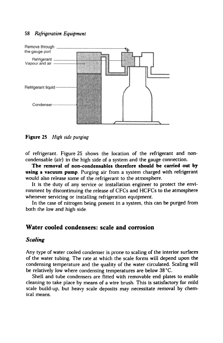
Figure 25
High side purging
of refrigerant. Figure 25 shows the location of the refrigerant and non-
condensable (air) in the high side of a system and the gauge connection.
The removal of non-condensables therefore should be carried out by
using a vacuum pump. Purging air from a system charged with refrigerant
would also release some of the refrigerant to the atmosphere.
It is the duty of any service or installation engineer to protect the envi-
ronment by discontinuing the release of CFCs and HCFCs to ttle atmosphere
whenever servicing or installing refrigeration equipment.
In the case of nitrogen being present in a system, this can be purged from
both the low and high side.
Water cooled condensers: scale and corrosion
Scaling
Any type of water cooled condenser is prone to scaling of the interior surfaces
of the water tubing. The rate at which the scale forms will depend upon the
condensing temperature and the quality of the water circulated. Scaling will
be relatively low where condensing temperatures are below 38 ~
Shell and tube condensers are fitted with removable end plates to enable
cleaning to take place by means of a wire brush. This is satisfactory for mild
scale build-up, but heavy scale deposits may necessitate removal by chem-
ical means.
Service diagnosis and repairs
59
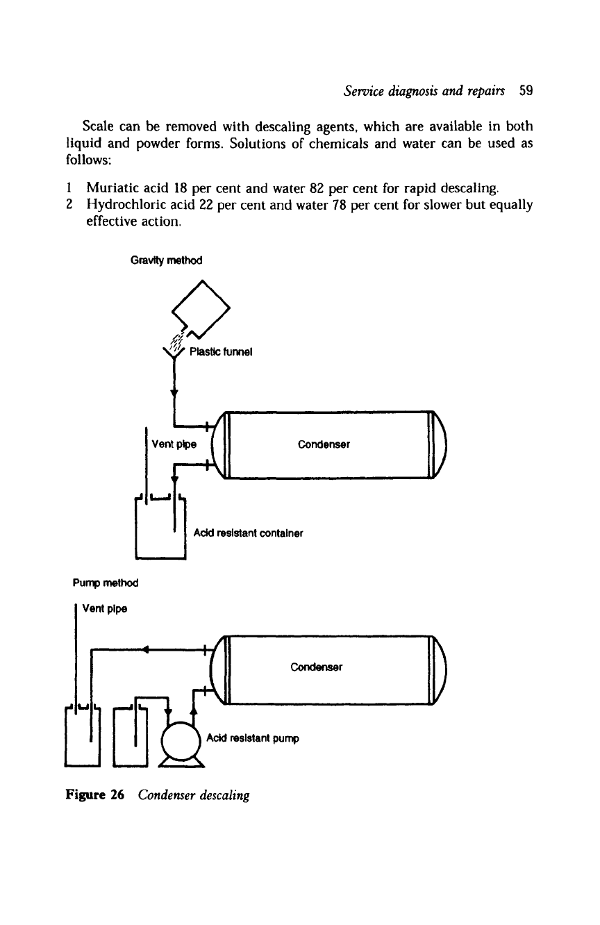
Scale can be removed with descaling agents, which are available in both
liquid and powder forms. Solutions of chemicals and water can be used as
follows:
1 Muriatic acid 18 per cent and water 82 per cent for rapid descaling.
2 Hydrochloric acid 22 per cent and water 78 per cent for slower but equally
effective action.
Gravity
method
Condenser
iJ,,, i ,L
t ~ntainer
Pump method
i
ol I
Vent pipe
~r
Acid resistant pump
Figure 26
Condenser descaling