Buede D.M. The Engineering Design of Systems Models and Methods
Подождите немного. Документ загружается.

More detailed literature on feedback control can be found in Dickinson
[1991], Dorny [1993], Franklin et al. [1994], and Van de Vegte [1994]. A graph-
theoretic approach for analyzing control systems has been developed called
signal flow graphs. Signal flow graphs are used to trans form a set of processes
with feedback into a single, composite process.
7.4.4 Evaluation of a Functional Hierarchy
A functional architecture can be evaluated for shortfalls and overlaps. A
shortfall is the absence of a functionality that is required to produce a desired
output from one or more inputs. Shortfalls can be divided into the following
categories: absence of the proper functionality for some set of inputs, inability
to produce a desired output, and insufficient feedback control to produce the
desired output.
Recall the definition of a function from Chapter 4. A function maps all
elements of the domain to some element in the range and does not map any
element of the domain into two distinct elements of the range. Whenever there
are potential inputs to the system with which the system’s functionality cannot
deal, the engineer of the system did not create a system function but rather a
system relation. A relation in Chapter 4 includes functions but also includes
those entities that fall short of a function. In fact, the most common types of
shortfall are the absence of or inappropriate functional responses to unexpected
inputs and to failure modes wi thin the system. For example, the elevator system
must be able to respond properly when a fire alarm sounds. Less obvious
unexpected inputs might be the need for a user to stop the elevator immediately.
Therefore the systems engineer must always enumerate all possible inputs,
including those inputs that are not wanted but can arrive. In the mathematical
terms of Chapter 4, a Cartesian product of possible inputs must be formed for
each function in the functional model of the functional architecture. This is
only necessary for the lowest level functions in the functional decomposition.
The Cartesian product of inputs for a function uses each category of input
shown in the functional model for a specific function. For each of these
categories there are usually several possible input states, some of which are not
desired. For example, if there were three possible input categories to a given
bottom-level function and each input category had three possible states, there
would be three-tuple formed by taking the Cartesian product of these three
input categories. The three-tuple would have 27 (3 3 3) different combina-
tions. The functional definition of this bottom-level functi on must account for
every one of these 27 possible combinations.
The second category of shortfall is the inability to produce a needed output.
This type of functionality will be obvious if all of the system’s outputs have been
defined. This is a major benefit of the external systems diagram in Chapter 6 and
the functional architecture discussed in this chapter. Evaluating for this category
of shortfall is not always possible without constructing an overall functional
architecture.
7.4 DEFINING A SYSTEM’S FUNCTIONS 231
The final shortfall addresses the quality of the outputs produced. Often this
quality falls short of that desired by the stakeholders because the engineers have
not incorporated sufficient feedback control, either internally to the system or
inclusive of the external systems. Missing needed feedback is a common
mistake made in the functional archit ecture. This is true not only for the
functional architecture of the system being designed for the operational phase
of the life cycle, but also for the functional architectures of the developmental
and manufacturing systems.
An overlap is a redundancy in functionality that is not needed to achieve
additional performance, for example, reliability. Functional overlaps, unlike
physical overlaps for redundancy, are not needed and therefore can only cause
problems.
A common technique for identifying shortfalls and overlaps is to follow each
scenario in the operational concept (Chapter 6) through the functional
architecture. Each scenario in the operational concept begins with a single
input to the system from one of the external systems and continues with a
sequence of inputs to and outputs from the system to various external systems.
Each scenario was developed by treating the system as a black box. Now is the
time to shine a light into that black box (producing a white box) and see what
functions the system is performing to transform the inputs into outputs. Start
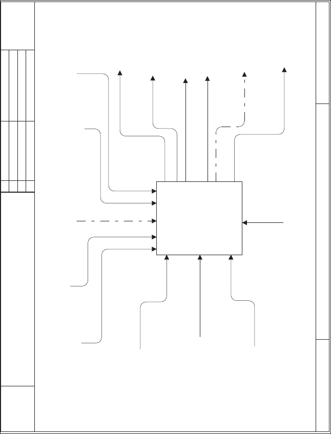
with the first input to the system for a given scenario (see Fig. 7.7); color the line
in the context diagram (A-0 page or node) for that input green (or whatever
color you choose). Find an interesting output of the system in the scenario and
color that output on the context page green also. In Figure 7.7 the input
selected was ‘‘Request for Elevator Servic e & Entry Support’’ by a potential
passenger, which is shown as a dotted-dashed line since color is too expensive
for a text book. The output selected was ‘‘Eleva tor Entry/Exit Opportunity’’
when the elevator arrives at the potential passenger’s floor; this output is also
shown as a dotted-dashed line.
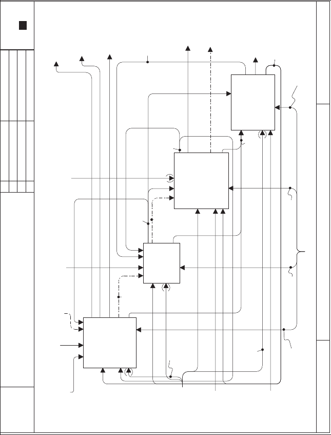
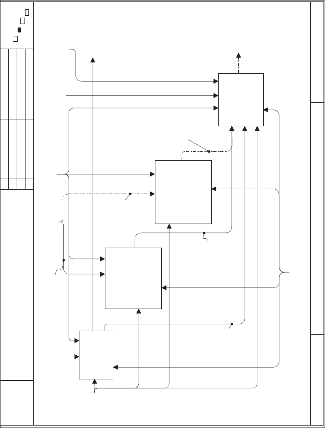
Now move to the AO page (node) and color these same two lines green; see
Figure 7.8 for the dotted-dashed lines. Now go to the function on the AO page
that received that input (the Al function in Fig. 7.8) and find the appropriate
output of the function that is needed to get to the output on the context page
and color the line associated with that output green. ‘‘Digitized Passenger
Request’’ is shown with a dotted-dashed line in Figure 7.8. Proceed to this next
function on the AO page and find the most appropriate output to color. This is
like looking through a house for clues to a mystery, searching room by room,
finding a clue in each room that leads to the next room, until finally the room is
found with the already identified path outside. In Figure 7.8, ‘‘Digitized
Passenger Request’’ led to the A2 function, ‘‘Control Elevator Cars.’’ The
appropriate output of this function was ‘‘Assignments to Elevator Cars,’’
leading to A3, ‘‘Move Passengers Between Floors,’’ which is where ‘‘Elevator
Entry/Exit Opportunity’’ was found.
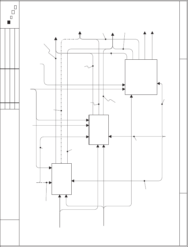
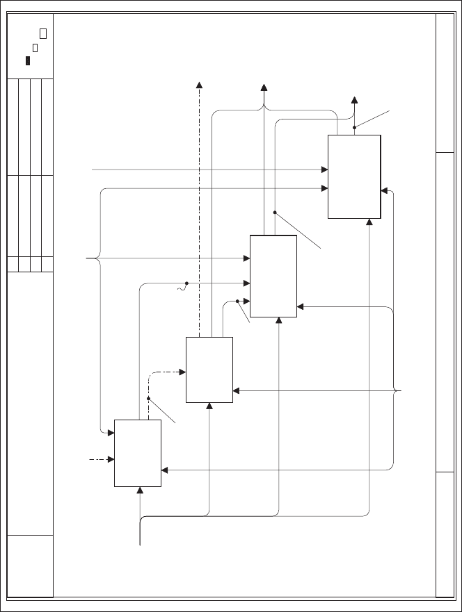
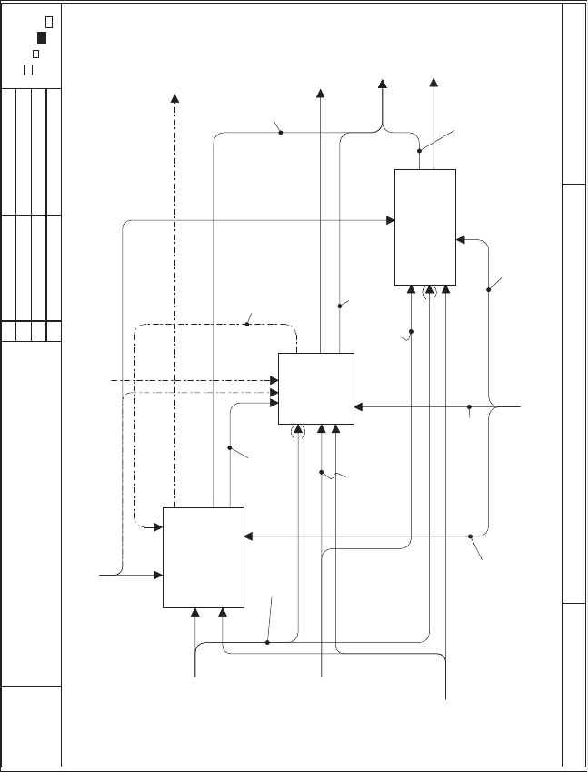
This process continues for every other page of the functional model. Figures
7.9–7.12 show this trace of the input and output from a given scenario
232 FUNCTIONAL ARCHITECTURE DEVELOPMENT
USED AT:
CONTEXT:
TITLE: NUMBER:
AUTHOR: Dennis Buede
PROJECT: Elevator Case Study
NOTES: 1 2 3 4 5 6 7 8 9 10
DATE: 05/24/99
REV:
WORKING
DRAFT
RECOMMENDED
PUBLICATION
READER DATE
P. 2
PROVIDE
ELEVATOR
SERVICES
A0
Passenger
Characteristics
Electric Power
& Emergency
Communication
Response
Service, Tests
& Repairs
Request for
Emergency
Support &
Emergency
Message
Request for
Floor & Exit
Support
Request for
Elevator
Service &
Entry support
Structural
Support,
Alarm Signals
& Building
Environment
ModifiedElevator
Configuration
& Expected
Usage Patterns
Passenger
Environment
Acknowledgment
that Request Was
Recieved & Status
Information
Diagnostic &
Status Messages
Elevator
Entry/Exit
Opportunity
Emergency
Support
Emergency
Communication
Elevator System
Top
x
George Mason
Univ.
Provide Elevator Services
A-0
NODE:
FIGURE 7.7 Scenario trace on the context page.
233
USED AT:
CONTEXT:
NODE: TITLE: NUMBER:
AUTHOR: Dennis Buede
PROJECT: Elevator Case Study
NOTES: 1 2 3 4 5 6 7 8 9 10
DATE: 05/24/99
REV:
WORKING
DRAFT
RECOMMENDED
PUBLICATION
READER DATE
P. 3
Passenger
Characteristics
Electric Power
& Emergency
Communication
Response
Service, Tests
& Repairs
Diagnostic &
Status Messages
Acknowledgment
that Request Was
Recieved & Status
Information
Passenger
Environment
Request for
Elevator
Service &
Entry support
Request for
Floor &
Exit Support
Request for
Emergency
Support &
Emergency
Message
Structural
Support,
Alarm Signals
& Building
Environment
ModifiedElevator
Configuration
& Expected
Usage Patterns
ACCEPT
PASSENGER
REQUESTS &
PROVIDE
FEEDBACK
A1
CONTROL
ELEVATOR
CARS
A2
MOVE
PASSENGERS
BETWEEN
FLOORS
A3
ENABLE
EFFECTIVE
MAINTENANCE
& SERVICING
A4
Digitized
Passenger
Requests
Assignments
for Elevator
Cars
Elevator
Entry/Exit
Opportunity
Emergency
Support
Elevator
Position &
Direction
Sensed
Malfunctions
Temporary
Modification to
Elevator
Configuration
Emergency
Communication
Electric
Power
Electric
Power
Elevator System
Passenger
Interface
Component
Elevator Control
Component
Elevator Cars
Component
Maintenance & Service
Component
Configuration
Controls
Diagnostic
Queries
PROVIDE ELEVATOR SERVICES
x
George Mason
Univ.
A0
FIGURE 7.8 Scenario trace continued in the AO diagram.
234
USED AT:
CONTEXT:
NODE: TITLE: NUMBER:
AUTHOR: Dennis Buede
PROJECT: Elevator Case Study
NOTES: 1 2 3 4 5 6 7 8 9 10
DATE: 05/24/99
REV:
WORKING
DRAFT
RECOMMENDED
PUBLICATION
READER DATE
P. 4
Request for
Floor &
Exit Support
Request for
Emergency
Support &
Emergency
Message
Request for
Elevator
Service &
Request for
Elevator
Service
Entry support
Acknowledgment
that Request Was
Recieved & Status
Information
Emergency
Support
Elevator
Position &
Direction
Sensed
Malfunctions
SUPPORT
WAITING
PASSENGERS
A11
SUPPORT
RIDING
PASSENGERS
A12
SUPPORT
PASSENGERS IN
EMERGENCY
A13
Request for
Entry Support
Digitized
Passenger
Requests
Emergency
Communication
Sensed
Floor-based
Malfunctions
Sensed
Car-based
Malfunctions
Sensed
Emergency
Malfunctions
Acknowledgments
& Status for
Waiting Passengers
Acknowledgments
& Status for
Riding Passengers
Acknowledgments
& Status for
Emergency
Passengers
Digitized
Emergency
Requests
Digitized
Requests
from Riding
Passengers
Digitized
Requests
from Waiting
Passengers
Passenger
Interface
Component
Nonemergency
Pass. Interface
Outside El. Cars
Nonemergency
Pass. Interface
Inside El. Cars
Emergency
Pass. Interface
Configuration
Controls
Diagnostic
Queries
x
George Mason
Univ.
ACCEPT PASSENGER REQUESTS & PROVIDE FEEDBACK
A1
FIGURE 7.9 Scenario trace continued in the Al diagram.
235
USED AT:
CONTEXT:
NODE: TITLE: NUMBER:
AUTHOR: Dennis Buede
PROJECT: Elevator Case Study
NOTES: 1 2 3 4 5 6 7 8 9 10
DATE: 05/24/99
REV:
WORKING
DRAFT
RECOMMENDED
PUBLICATION
READER DATE
P. 5
Elevator
Position &
Direction
Request for
Elevator
Service
Acknowledgments
& Status for
Waiting Passengers
Sensed
Floor-based
Malfunctions
ACCEPT
PASSENGER
REQUEST
A111
DIGITIZE
REQUEST
A112
ACKNOWLEDGE
PASSENGER'S
REQUEST
A113
PROVIDE
STATUS
INFORMATION
FOR EACH CAR
A114
Passenger
Request
Request
Alert
Digitization
Successful
Acknowledgment
of Request for
Elevator
Service
Status
Information
Digitized
Requests
from Waiting
Passengers
Nonemergency
Pass. Interface
Outside El. Cars
Diagnostic
Queries
Configuration
Controls
x
George Mason
Univ.
SUPPORT WAITING PASSENGERSA11
FIGURE 7.10 Scenario trace continued in the Al1 diagram.
236
USED AT:
CONTEXT:
NODE: TITLE: NUMBER:
AUTHOR: Dennis Buede
PROJECT: Elevator Case Study
NOTES: 1 2 3 4 5 6 7 8 9 10
DATE: 05/24/99
REV:
WORKING
DRAFT
RECOMMENDED
PUBLICATION
READER DATE
P. 6
ModifiedElevator
Configuration
& Expected
Usage Patterns
Assignments
for Elevator
Cars
Elevator
Position &
Direction
Sensed
Malfunctions
MONITOR
LOCATION
OF ALL CARS
A21
MONITOR
LOCATION AND
DIRECTION OF
ALL
NON-PRIORITY
WAITING
A23
ALLOCATE
CARS TO
PASSENGER
PICK UP
STOPS
A24
Digitized
Passenger
Requests
List of all
Cars with
Direction &
Location
List of all
Floors with
Waiting
Nonpriority
Passengers
& Desired
Direction
List of all
Floors with
Waiting
priority
Passengers
& Desired
Direction
Temporary
Modification to
Elevator
Configuration
MONITOR
LOCATION AND
DIRECTION OF
ALL PRIORITY
WAITING
PASSENGERS
A22
Digitized
Priority
Passenger
Requests
Digitized
Nonpriority
Passenger
Requests
Elevator Control
Component
Configuration
Controls
Diagnostic
Queries
x
George Mason
Univ.
CONTROL ELEVATOR CARSA2
FIGURE 7.11 Scenario trace continued in the A2 diagram.
237
USED AT:
CONTEXT:
NODE: TITLE: NUMBER:
AUTHOR: Dennis Buede
PROJECT: Elevator Case Study
NOTES: 1 2 3 4 5 6 7 8 9 10
DATE: 05/24/99
REV:
WORKING
DRAFT
RECOMMENDED
PUBLICATION
READER DATE
P. 7
Passenger
Characteristics
Passenger
Environment
Electric Power
& Emergency
Communication
Response
Assignments
for Elevator
Cars
Elevator
Entry/Exit
Opportunity
Elevator
Position &
Direction
Sensed
Malfunctions
RECEIVE &
DISCHARGE
PASSENGERS
A31
TRAVEL
TO NEXT
STOP
A32
PROVIDE
COMFORTABLE
ATMOSPHERE
A33
Electric
Power
Travel OK
Message
Travel
Stopped
Message
Passenger
Weight
Passenger
Heat
Sensed
Discharge
Malfunctions
Sensed
Travel
Malfunctions
Sensed
Comfort
Malfunctions
Elevator Cars
Component
Elevator
Car Door
Elevator Cab
& Door
Elevator Car
Sensors & Controls
Configuration
Controls
Diagnostic
Queries
x
George Mason
Univ.
MOVE PASSENGERS BETWEEN FLOORSA3
FIGURE 7.12 Scenario trace completed in the A3 diagram.
238
throughout the entire functional model of the elevator system in the case study
that can be downloaded from http://www.theengineeringdesignofsystems.com.
In addition, defining failure modes for the system and creating error
detection and recovery functionalities within the common operating modes as
well as the failure modes is critical. These functi onalities for error detection and
recovery are critical for stakeholder usability. How often has your computer
shut down with no warning and little support for saving open files? The more
mature an operating system is, the more functionality the operating system
commonly has for saving open files as part of the crash, and the more unlikely
such crashes are. Deta ils on functionality for addressing error detection and
recovery are covered later in the chapter.
7.5 DEVELOPMENT OF THE FUNCTIONAL DECOMPOSITION
The literature [Marca and McGowan, 1988] surrounding the structured
analysis and design technique (SADT), which became IDEF0, suggests the
following activities for creating a functional decomposition with inputs,
controls and outputs:
Determine the purpose and viewpoint.
Generate a data list, based upon the system’s boundaries (the external
systems diagram).
Generate an activity list.
Define the AO diagram, and the level 1 functional decomposi tion.
Draw the context diagram, A-0 (this has already been done, based on the
external systems’ diagram).
Continue this process while decomposing the level 1 functions.
The purpose and viewpoint define the issues that the IDEF0 model will address.
The purpose for systems engineering applications is straightforward, namely to
depict the functional activities of the system in a particular phase of the
system’s life cycle; as can be seen in the elevator case study (available on the
author’s web site) there is a separate IDEF0 model for each phase. Similarly,
the viewpoint is the systems engineering team; this team is creating the
functional architecture, of which the IDEF0 model is a part, for the purposes
of designing the system. Typically, there are a number of stakeholders with a
somewhat diverse set of opinions that are concerned about each phase of the
life cycle; the systems engineering team should include representatives of these
stakeholders and has ultimate responsibility to integrate these opinions.
The data list of inputs, controls, and outputs for the system’s top-level
function should already be available from the external systems’ diagram.
Nonetheless, this is an excellent time to review and crit ique the data list to
determine if there are any missing or redundant items.
7.5 DEVELOPMENT OF THE FUNCTIONAL DECOMPOSITION 239
Next, we have the first of many decomposition decisions. How should the top-
level system function be decomposed? Spending some time gathering information
and brainstorming about system functions for each phase is always a good idea,
in addition to creating an activity list from which to choose or synthesize the
functional decomposition. For the operational phase of the life cycle a previous
section presented the options of starting with the operational modes of the
system or alternatively with the functional taxonomy derived from the Hatley–
Pirbhai [1988] architecture template. At this point in time the systems engineer-
ing team certainly has not finalized the definition of operating modes for the
system. In fact, the functional decomposition will inevitably be modified over
time as the performance of the allocated architecture is evaluated. Figure 7.3
depicted the elevator’s top-level functional decomposition for the operational
phase in terms of the Hatley–Pirbhai template.
There are many ways to gather information:
Review documents, but watch for viewpoint changes.
Observe operations, but be careful about the details that you do not know
well enough to recognize and the need to make major changes from the
current system to the system under development.
Conduct interviews; questionnaires can be used but have very limited
value (be sure you get the right experts).
Invent a strawman for the expert s to critique.
Create several alternate decompositions and create a composite strawman
based on the best features of each after some critical discussion (this
creativity technique is often called the ‘‘gallery’’).
Once a working version of the functional model is creat ed, the functional
model should be revie wed by individuals that have substantial knowledge and
varying perspectives about the system’s functioning in a given life-cycle phase.
This review process sho uld:
Try alternate decompositions.
Disaggregate the functions differently.
Bundle and unbundle arrows differently.
Reevaluate functional dominance in terms of feedback and control.
Catch interface errors.
As part of this review process creating a data model of the inputs, controls, and
outputs using an entity–relationship–attr ibute or higraph model would be wise.
These techniques are discussed in Chapter 12. The data model often introduces
critical design issues that have been overlooked in the functional or process
model.
How far should the functional decomposition be carried out? Generally
speaking, the functional decomposition should proceed to the second, third,
240 FUNCTIONAL ARCHITECTURE DEVELOPMENT