Buede D.M. The Engineering Design of Systems Models and Methods
Подождите немного. Документ загружается.

functional architecture. That is, if you added, deleted, or modified any
input, controls, or outputs for the system, modify your input/output
requirements. Also update your external systems diagram if any
changes are needed.
7.5 For the manufa cturing system for an air bag system:
i. As part of the systems engineering development team, use IDEF0 to
develop a functional architecture. The functional architecture should
address all of the functions associated with the manufacturing system
for an air bag. This functional architecture should be at least two
levels deep and should be four levels deep in at least one functional
area that is most complex. Note that you will be graded on your
adherence to proper IDEF 0 semantics and syntax, as wel l as the
substance of your work.
ii. Pick three scenarios from the operational concept and describe how
these scenarios can be realized within your functional architecture by
tracing functionality paths through the functional architecture. Start
with the external input(s) relevant to each scenario and show how
each input(s) is(are) transformed by tracing from function to function
at various levels of the functional decomposition, until the scenario’s
output(s) is(are) produced. Highlight with three different colored pens
(one color for each scenario) the thread of functionality associated
with each of these three scenarios.
If your functional architecture is inadequate, make the appropriate
changes to your functional architecture.
iii. As part of the systems engineering development team for the
manufacturing system for an air bag, update your requirements
document to reflect any insights into requirements that you obtained
by creating a functional architecture. That is, if you added, deleted, or
modified any input, controls, or outputs for the system, modify your
input/output requirements. Also update your external systems dia-
gram if any changes are needed.
PROBLEMS 251

Chapter 8
Physical Architecture
Development
8.1 INTRODUCTION
The physical architecture of a system is a hierarchical description of the
resources that comprise the system. This hierarchy begins with the system
and the system’s top-level components and progresses down to the configura-
tion items (CIs) that comprise each intermediate component. The CIs can be
hardware or software elements or combinations of hardware and software,
people, facilities, procedures, and documents (e.g., user’s manuals).
Section 8.2 introduc es the distinction between a generic and instantiated
physical architecture. The generic physical architecture defines the hierarchy in
general terms, for example, two processors with associated software, a person,
and a building. The instantiated physical architecture lays out the specifics of
the processors, software, person, and building in enough detail to permit
performance modeling of the system related to the requirements being
addressed. The intent of systems engineers should not be to design these
components but rather to state representative instantiations for the generic
components that are sufficient to model the performance of the system and
ensure that the requirements decomposition process makes sense.
Section 8.3 defines a method for developi ng alternatives for the generic and
instantiated physical architectures of the system. The development process
proposed here emphasizes multiple alternatives, especially for the instantiated
physical architecture, based on the supposition that the design process is quite
difficult for even moderate extensions of existing systems. The following quote
The Engineering Design of Systems: Models and Methods, Second Edition. By Dennis M. Buede
Copyright
r 2009 John Wiley & Sons, Inc.
252
by Guindon [1990, p. 308] expresses the importance of this approach:
System design often involves novelty. Even though the designer may be thor-
oughly familiar with the design process itself, there may not be any precedent in
the literature for the system to be designed. — It may be a new technology. More
frequently, the system may simply involve some novelty in an otherwise well-
understood problem. The novelty may range from a novel combination of
requirements for a familiar type of system in a familiar problem domain. As a
consequence, there is often no predetermined solution path from the requirements
to the finished artifact [Newell, 1969; Nii, 1986; Reitman, 1965; Rittel, 1972;
Simon, 1973]. Thus system design frequently requires the creation of new
solutions interleaved with the application of known solutions.
Section 8.4 introduces some creativity techniques to aid in the development
of the alternate physical architectures. The morphological box is the prim ary
technique employed and illustrated in this chapter. The morphological box
dates back to the 1940s and breaks a system into segments as defined by the
generic physical architecture; it then provides for the listing of alte rnate
instantiated physical components for each segment. Other techni ques that
have been proposed and utilized are classified as either brainstorming or
brainwriting and are also discussed. See West [2007]. Selecting one or more
instantiated components from each component produces an alternative for an
instantiated physical architecture for the system.
Engineers commonly resort to describing the system’s architecture in a non-
mathematics-based graphical format. Block diagrams, the commonly used and
non-standardized graphical format, are presented in Section 8.5 to represent the
physical coupling of the system’s components. A block diagram provides a box or
block for each component. The links between the blocks represent the major flows
of energy or information between the components represented by the blocks.
Section 8.6 addresses major issues and associated concepts in the develop-
ment of a physical architecture. The concepts of centralized and decentralized,
distributed, and client–server architectures are discussed and illustrated. Also
redundancies in hardware, software, information, and time are discussed as
ways to achieve fault tolerance via the physical architecture.
The exit criterion for the development of the physical architecture is the
provision of a single physical architecture that is satisfactory in terms of detail,
quantity, and quality for development of the allocated architecture. This
satisfaction of detail, quantit y, and quality is typically preceded by the creation
of several alternate physical architectures for consideration during the develo-
pment and refinement of the allocated architecture.
8.2 GENERIC VERSUS INSTANTIATED PHYSICAL ARCHITECTURES
The physical architecture provides resources for every function identified in the
functional architecture. Since every phase of the life cycle is addressed in the
8.2 GENERIC VERSUS INSTANTIATED PHYSICAL ARCHITECTURES 253
requirements and is being addressed in the functional architectures, there must
be a physical architecture for each system associated with the system’s life cycle.
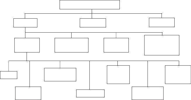
Recall the sample physical architecture from Chapter 1 (repeated here as
Figure 8.1). Note that this physical architecture includes the vehicle, the support
resources for the vehicle during the operational and maintenance phases, and the
training resources, which may be training for the operational phase or the
training phase. Also, note that even at the third level of the physical architecture,
the components are combinations of hardware, software, and other devices.
Military standard MIL-STD-881B [1993] contains a Work Breakdown
Structure (WBS) for Defense Material Items. The WBS is often very similar
to the physical architecture because the work is organized along the lines of the
resources that require development or procurement. For an aircraft system
there are 10 elements that partition the syst em, as shown in the first column of
Table 8.1. These elements span six of the seven life-cycle phases (shown in the
second column) defined in Chapter 1. The only phase that is absent from this
list is retirement, the commonly forgotten phase.
In the same military standard, 17 resource categories, shown in Table 8.2,
are defined as a partition of the generic air vehicle. These lists or partitions of
the resources for the physical architecture are most useful as memory joggers.
For some aircraft, some of these elem ents are not relevant; for example, airlift
aircraft do not need armament or antisubmarine warfare. More importantly, as
technology advances some of these elements are outd ated. With the advent and
advance of distributed computing, the central computer element is not relevant
or misleading. In addition, at this level of the physical architecture it is often
too early to separate hardware and software.
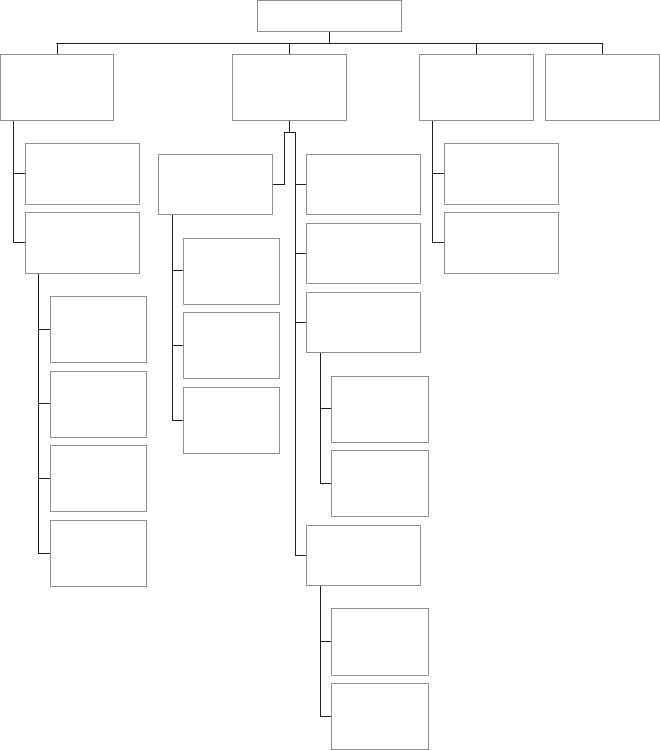
Common resource categories for an aircraft have been described in Figure 8.1
and Tables 8.1 and 8.2. The resource categories for the elevator’s physi-
cal architecture from the case study, which can be downloaded from
F-22 Weapon System
Vehicle Training
Support
Avionics
Systems
Utilities &
Subsystems
Cockpit
Systems
Vehicle
Management
System
Electronic
Warfare
Navigation,
Identification
Processing
Controls
&
Displays
Stores
Management
Inertial
Reference
System
Radar
FIGURE 8.1 Sample physical architecture (F-22 Type A Spec) (from Reed [1993]).
254
PHYSICAL ARCHITECTURE DEVELOPMENT

http://www.theengineeringdesignofsystems.com, are shown in Figure 8.2. All of
these resource categories are examples of a generic physical architecture. A
generic physical architecture is a description of the partitioned elements of the
physical architecture without any specification of the performance characteristics
of the physical resources that comprise each element (e.g., central processing
unit). An instantiated physical architecture is a generic physical architecture to
which complete definitions of the performance characteristics of the resources
have been added. An instantiated physical architecture for the elevator system
would be specific about the call announcement component (e.g., liquid crystal
lights), destination control (e.g., push buttons), and the like.
One element that is left out of most physical architectures is the set of
procedures that are developed for the users of the system to follow. These
procedures are explicit operating, maintenance, or support instructions pro-
vided in the font of a user’s or operator’s manual. These manuals usually
accompany the system when the system is delivered. These procedures are the
focus of attention during the training that is delivered to the users, maintainers,
TABLE 8.1 WBS Elements and Related Life Cycle Phases
WBS Elements Life Cycle Phase
Air vehicle Operational
Systems engineering/Program management Development
System test and evaluation Development
Training Training
Data Manufacturing and Refinement
Peculiar support equipment Operational
Common support equipment Operational
Operational/site activation Deployment
Industrial facilities Manufacturing
Initial spares and repair parts Operational
TABLE 8.2 Resource Categories for a Generic Air Vehicle
Airframe
Propulsion
Air vehicle application software
Air vehicle system software
Communications/Identification
Navigation/Guidance
Central computer
Fire control
Data display and controls
Survivability
Reconnaissance
Automatic flight control
Central integrated checkout
Antisubmarine warfare
Armament
Weapons delivery
Auxiliary equipment
8.2 GENERIC VERSUS INSTANTIATED PHYSICAL ARCHITECTURES 255
or supporters of the system. Systems engineers should not forget or ignore this
element of the system’s physical architecture, as was done with the initial air
bag system that was described as a case study in Chapter 6. After the serious,
and often deadly, effects on children and small adults were noticed, a series of
procedures for the placement (or lack thereof) of children and small adults in
the front seat were released. Common practice in the development of a syst em is
to accommodate problem issues identified during qualification of the system
(see Chapter 10) by amending and expanding the procedures defining how the
system will be used. Procedures such as these represent the way in which the
system’s functionality moves from the system under development to the users.
Elevator Call
Announcement
Component
Destination
Control
Component
Door
Control
Component
Emergency
Component
Phone
Component
Car Control
Component
Passenger
Interface
Component
Cab
Component
Interior Door
Component
Ventilation
& Lighting
Component
Car Component
Shaft Structural
Component
Exit Component
& Controls
Floor Stop
Component
Leveling
Component
Shaft Switch
Component
Normal
Drive/Brake
Component
Emergency
Braking
Component
Drive/Brake
Component
Elevator
Car/Shaft
Component
Hardware
Component
Software
Component
Control
Component
Maintenance
& Self-Test
Component
Elevator System
FIGURE 8.2 Generic physical architecture from the elevator case study.
256
PHYSICAL ARCHITECTURE DEVELOPMENT
8.3 OVERVIEW OF PHYSICAL ARCHITECTURE DEVELOPMENT
The definition of the physical architecture, as described here, is done one level
of the tree at a time. Our approach here is a top-down process. There are many
systems engineers that have successfully used a bottom-up design process for
the physical part of the system (just as we described the bottom-up approach in
the previous chapter for the functional architecture). Experience and creativity
are critical for this part of the engineering process. While experience is a must;
do not underestimate the importance of creativity.
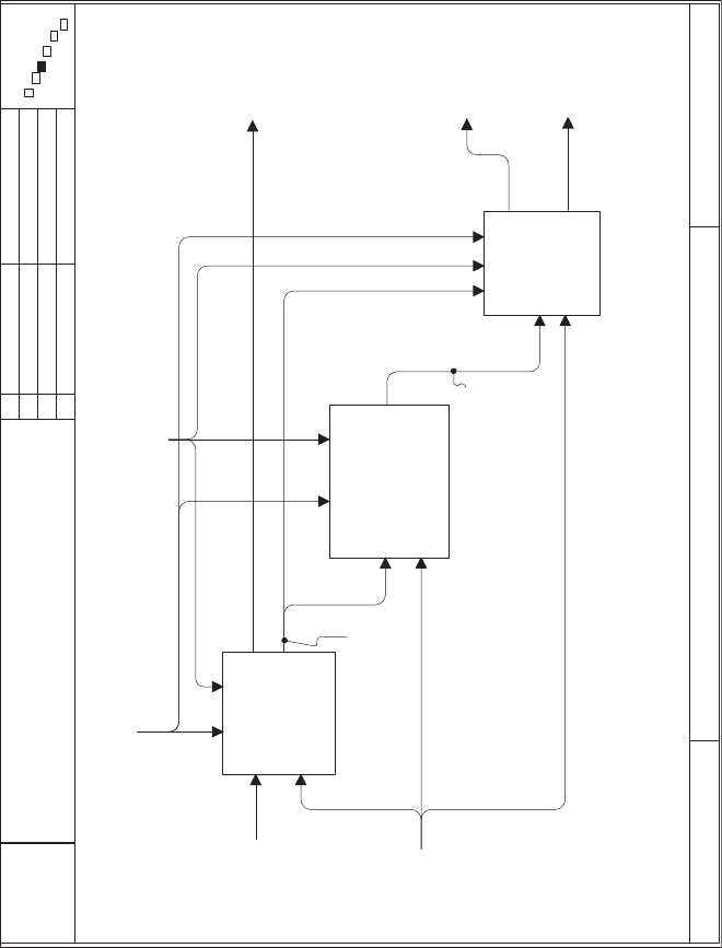
There are many possible decompositions of the process ‘‘Design
System Physical Architecture.’’ The one chosen here (Figure 8.3, taken from
Appendix B) emphasizes the concepts of generic and instantiated physical
architectures. A second justification of this decomposition is the belief that the
allocated architecture development is predicated on having a variety of
interesting physical architectures to match with the functional architecture.
Therefore, the primary product of this function for designing the physical
architecture is a reasonable number of interesting physical architectures that
can be combined wi th the functional architecture and evaluated to determine
their effectiveness in meeting the objectives established in the requirements.
The structure of the generic physical architecture is first selected while
working in parallel with the development of the functional architecture. As
discussed in Chapter 7 and elaborated on in Chapter 9, there are great
advantages in defining the internal interfaces of the system to have the
functional and physical architectures match; that is, enable a one-to-one and
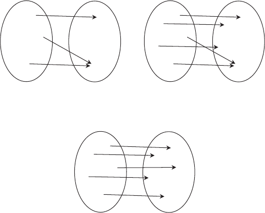
onto allocation of functions to components. See Figure 8.4 to review the
distinctions between a relation and a function, and the additional restrictions
for a function that is one-to-one and onto. While there are many advantages to
a one-to-one and onto mapping of functions and components, this may not
always be possible and should not be forced.
First, a generic physical architecture must be developed. The generic
physical architecture provides common designators for physical resources in
a hierarchical decomposition that partitions the system into greater and greater
detail. Although this generic physical architecture has no substance in the sense
of specific physical items, this structure is still very important. Some instan-
tiated physical architectures can be eliminated from consideration just on the
basis of the division of the system into components. Therefore serious thought
and creativity should be devoted to this initial task.
The second function in the decomposition addresses the creation of a
morphological box to assist in generating a set of creative instantiated archi-
tectures to analyze during the development of the allocated architecture. A
morphological box is a matrix in which the columns (or rows) represent the
components in the generic physical architecture. The boxes in a given column (or
row) then represent alternate choices for fulfilling that generic component. Each
option should have well-defined performance (and cost) characteristics. Section 1
describes the morphological box in more detail and provides several examples.
8.3 OVERVIEW OF PHYSICAL ARCHITECTURE DEVELOPMENT 257
USED AT:
CONTEXT:
NODE: TITLE: NUMBER:
AUTHOR: Dennis Buede
PROJECT: Engineering Design of a System
NOTES: 1 2 3 4 5 6 7 8 9 10
DATE: 05/24/99
REV:
WORKING
DRAFT
RECOMMENDED
PUBLICATION
READER DATE
P. 8
System-level
Operational
Concept
Candidate
Physical
Architectures
System-level
Physical
Architecture
System-level
Functional
Architecture
Candidate
Generic
Physical
Architectures
Brainstorm and
Select a Generic
Physical
Architecture
A1131
Generate a
Morphological Box
for Alternate
Instantiated Physical
Architecture
A1132
Select
Alternate
Instantiated
Physical
Architecture
A1133
Generic
Physical
Architecture
Morphological
Box
Physical
Architecture
Changes
x
GMU Systems
Engineering
Program
Design System Physical Architecture
A113
Stakeholders’ &
System Requirements,
Objectives Hierarchy,
Boundary & Qualification
System Requirements
FIGURE 8.3 Development process for the physical architecture.
258
The third function in this decomposition uses the morphological box to aid
in the selection of as many alternate instantiated physical architectures as are
needed to feed the process of selecting an allocated architecture. An alternative
instantiated physical architecture would be the selection of an option from
each of the generic components in the morphological box. Examples of the
morphological box are provided in the following sections.
The functional decomposition shown in Figure 8.3 suggests that the three
functions are performed in a serial fashion, which is true with the following
caveat: The changes to the physical architecture that are sent from the
development of the allocated architecture trigger the repetition of these three
functions. Each repetition could cause changes to the generic physical archi-
tecture, modifications to the morphological box due to the changed generic
architecture or other changes dictated by the allocated architecture, and a
reselection of alternate instantiated physical architectures.
8.4 CREATIVITY TECHNIQUES
Initially creating more choices than are useful to con sider in a detailed analysis
process is wise. This generation of excess alternatives means there is a greater
Functions
f
2
f
3
f
4
f
1
f
5
Components
c
2
c
3
c
4
c
1
c
5
Relation for the allocation
of functions to components
Functions
f
2
f
3
f
4
f
1
f
5
Components
c
2
c
3
c
4
c
1
c
5
Function for the allocation
of functions to components
Functions
f
2
f
3
f
4
f
1
f
5
Components
c
2
c
3
c
4
c
1
c
5
One-to-one and onto
function for the allocation
of functions to components
FIGURE 8.4 Need for a one-to-one and onto functional allocation of functions to
components.
8.4 CREATIVITY TECHNIQUES 259
chance that the best choices are being considered in the final analysis. There are
many possible creativity enhancing techniques that have been used by engineers
to develop new and interesting solutions to old and new problems. This section
begins by focusing on one technique, the morphological box, that has proven
useful a number of times. Then a larger review of techniques is provided.
8.4.1 Morphological Box
Originally proposed by Zwicky [1969] during World War II and then expanded
by Allen [1962], morphological analysis (more commonly known in some
disciplines as morphological box) divides a problem into segments and posits
several solutions for each segment. In the two-dimensional version, a table is
created with columns (or sometimes rows) pertaining to the generic compo-
nents of the physical architecture. Then the elements of each column are filled
with competing specific instantiations of each component. The instantiations in
a given column need not fit together; in fact, each column corresponds to a
section of a cafeteria (e.g., salads, vegetables, meat, deserts). A meal would then
consist of a selection from each section of the cafeteria. A system’s instantiated
physical architecture, analogously, is a selection of one box from each column
(generic component) of the morphological box. As part of the morphological
analysis, each instantiation (one from each column) will be based upon a subset
of the system’s objectives. For example, one subset of objectives might be low
cost; another, high-speed pe rformance; and a third, high usability. Each of
these instantiations is, in fact, a theme for the design of the system.
Table 8.3 presents a morphological box (generic components and choices)
for a hammer. This morphological box contains five generic components of a
hammer: the length of the handle, the material that the handle is made of, the
size and surface of the head of the hammer used for striking, the weight or
density of the hammer head, and the angle associated with the he ad of the
hammer used for removing nails. Any hammer is one cell from each of the five
columns. For example, one hammer design is obtained by taking the top cell
of each column: 8-inch handle made of Fiberglass with a rubber grip using a
1 inch diameter flat steel head that weighs 12 ounces and has a steel claw that is
nearly perpendicular to the handle. There are 2 5 4 4 2 = 320 different
possible hammers defined in this table, assuming none of the combinations are
infeasible. Yet when you go to the hardware store, there may be only a dozen
choices. For real systems there are usually millions of possible combinations.
Yet many design teams only consider one or two in any detail, making it very
likely that they are missing several creative, high-quality designs. The big
advantage of the morphological box is that it forces the design team to
recognize that there are many possible solutions to the design problem. The
conversation about what design alternative best satisfies the requirements
follows naturally.
While the morphological box is a simple concept, there are a number of
subtle issues that need to be addressed. First and obviously, there should be at
260 PHYSICAL ARCHITECTURE DEVELOPMENT