Cold and Hot Forging: Fundamentals and Applications / Edited by Taylan Altan, Gracious Ngaile, Gangshu Shen
Подождите немного. Документ загружается.

Inverse Analysis for Simultaneous Determination of Flow Stress and Friction / 87
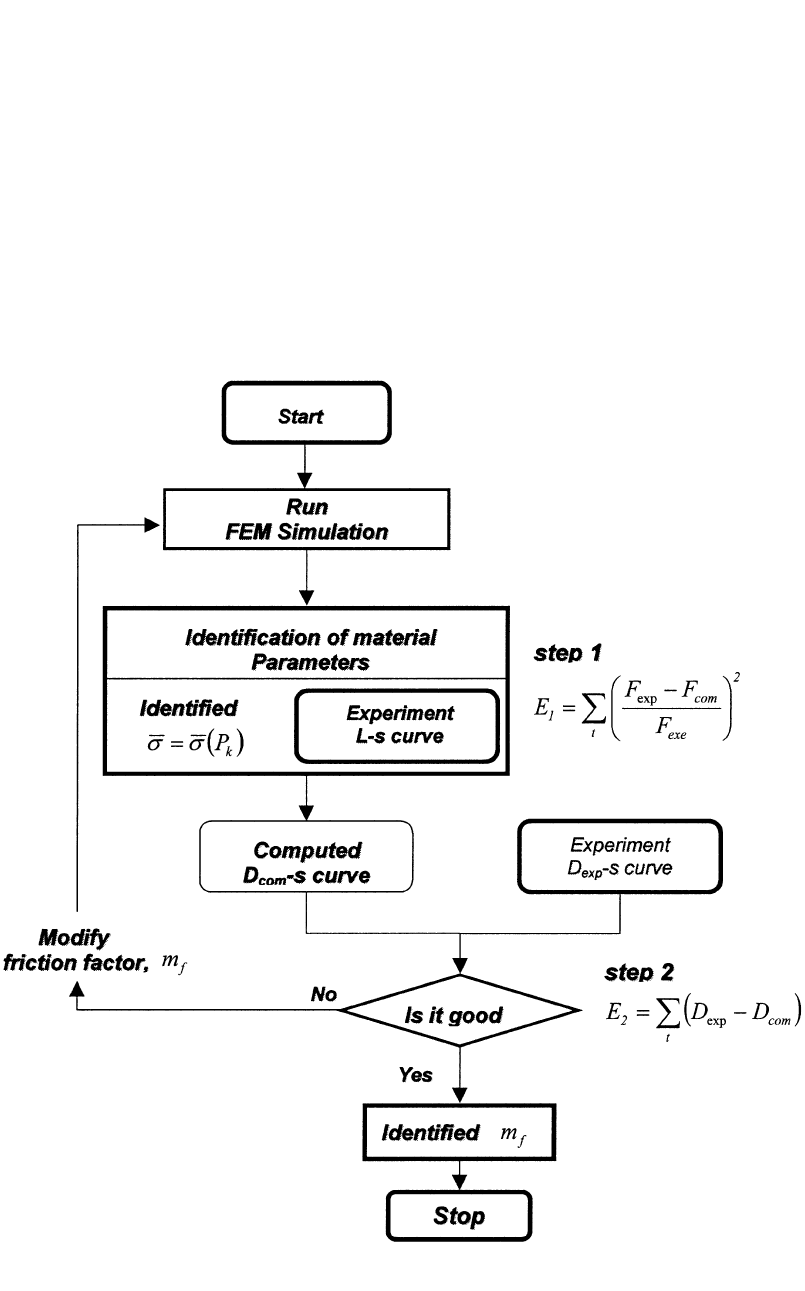
Fig. 8.3
Flow chart of simultaneous determination of flow stress and friction. L-s, load versus stroke; D-s, bulge diameter versus
stroke; m
f
, friction factor
obtained from the ring compression test. The in-
vestigated material was assumed to follow
strain-hardening behavior and the following
power-law-type flow stress equation was consid-
ered.
n
¯r ⳱ K¯e (Eq 8.6)
Therefore, a set of material parameters defined
by P
k
⳱ {K,n} and friction factor m
f
are the
unknown parameters that have to be identified.
Two experimental quantities: (1) the measured
load-stroke curve and (2) the maximum diame-
ter of the specimen at the end of stroke were
used as experimental values in the inverse anal-
ysis.
8.5.2 Experiment
Aluminum rings made from Aluminum 6061-
T6 with 2.13 in. OD ⳯ 1.06 in. ID ⳯ 0.71 in.
height (54 mm OD ⳯ 27 mm ID ⳯ 18 mm
height) were compressed to various reductions
88 / Cold and Hot Forging: Fundamentals and Applications
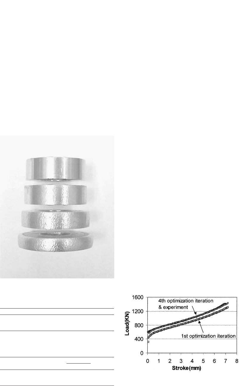
Fig. 8.4 Compressed ring samples
Table 8.2 Percent decrease in ID of ring
Reduction in height, % Decrease in ID of ring, %
7.2 ⳮ1.48
22.2 ⳮ2.96
40.0 ⳮ1.85
Table 8.3 Predicted inverse analysis results
(ring test)
Decrease in ID
K-value, MPa
Friction (m
f
) of ring, % ksi MPa n-value
0.2 Ⳮ0.5 65 446 0.073
0.15 ⳮ5.9 67 459 0.076
0.175 ⳮ1.7 66 452 0.074
Fig. 8.5
Comparison of computed and experimental load-
stroke curves (ring test)
rized in Table 8.3. Three inverse analyses were
conducted by varying the friction factor from
0.15 to 0.2. As initial guesses of material param-
eters, K ⳱ 430 (MPa) and n ⳱ 0.1 were used
for every case. When the friction factor 0.175
was assumed, the inverse analysis prediction
produced only 8.1% underestimation in ID com-
parison of the ring. Thus, a combination of fric-
tion factor m
f
⳱ 0.175 and flow stress ⳱¯r
(MPa) gives the best minimum for the
0.074
452¯e
objective function. As can be seen in Fig. 8.5,
after four optimization iterations, computed and
experimental loads are nearly identical.
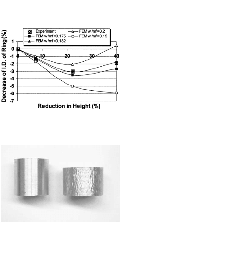
8.5.4 Verification of the
Determined Friction Factor
To verify the accuracy of determined friction
factor, FEM simulations using the determined
flow stress with friction factor of 0.175 were
conducted for various friction factors. Thus, the
ring calibration curves were generated as shown
in Fig. 8.6. It is seen that measurements match
well the curve obtained with the friction factor
of 0.182, which is very close to 0.175.
8.5.5 Verification of the
Determined Flow Stress
In order to verify the flow stress determined
with friction factor by the inverse analysis, the
aluminum cylinders with a 30 mm diam ⳯ 30
mm height were upset to 38% reduction in
height. To minimize interface friction, the inter-
face was lubricated with Ecoform lubricant
made by Fuchs. As shown in Fig. 8.7, the lu-
brication nearly eliminated bulging in upsetting
of cylinder. Using the measured load-stroke
curve, flow stress ⳱ (MPa) was ob-
0.067
¯r 437¯e
tained. The difference between the flow stress
in height. The rings were lubricated with Teflon
spray on all surfaces of the samples and on the
top and bottom dies. In order to observe the in-
ternal diameter variation the test was stopped at
reductions of 7.2, 22.2, and 40%. Figure 8.4
shows the compressed ring samples, and Table
8.2 shows the decrease in ID of the ring at dif-
ferent reductions.
8.5.3 Determination of
Flow Stress and Friction
The results of identifed parameters (K-value
and n-value) in the flow stress equation and fric-
tion factor by the inverse analysis are summa-
Inverse Analysis for Simultaneous Determination of Flow Stress and Friction / 89
Fig. 8.7 Compressed ring samples
data obtained in ring and cylinder compression
tests is about 3.3% in K-value and 9.5% in n-
value, respectively.
REFERENCES
[Boyer & Massoni, 2001]: Boyer, B., Massoni,
E., “Inverse Analysis for Identification of Pa-
rameters During Thermo-Mechanical Tests,”
Simulation of Materials Processing: Theory,
Method and Applications, K.-I. Mori, Ed.,
2001, p 281–284.
[Chenot et al., 1996]: Chenot, J., Massoni, E.,
Fourment, L., “Inverse Problems in Finite
Element Simulation of Metal Forming Pro-
cesses,” Eng. Comput., Vol 13 (No. 2/3/4),
1996, p 190–225.
[Cho et al., 2003]: Cho, H., Ngaile, G., “Si-
multaneous Determination of Flow Stress and
Interface Friction by Finite Element Based In-
verse Analysis Technique,” Ann. CIRP, Vo l
52/1, 2003, p 221–224.
[Dahl et al., 1999]: Dahl, C., Vazquez, V., Al-
tan, T., “Determination of Flow Stress of 1524
Steel at Room Temperature Using the Com-
pression Test,” Engineering Research Center
for Net Shape Manufacturing, ERC/NSM-99-
R-22.
[Pietrzyk et al., 2001]: Pietrzyk, M., Szyndler,
D., Hodgson, P.D., “Identification of Param-
eters in the Internal Variable Constitutive
Model and Friction Model for Hot Forming
of Steels,” Simulation of Materials Process-
ing: Theory, Method and Applications, Mori,
Ed., 2001, p 281–284.
[Zhiliang et al., 2002]: Zhiliang, Z., Xinbo, L.,
Fubao, Z., “Determination of Metal Material
Flow Stress by the Method of C-FEM,” J.
Mater. Process. Technol., Vol 120, 2002, p
144–150.
Fig. 8.6
Ring calibration curves obtained with ⳱¯r
(MPa)
0.074
452¯e

CHAPTER 9
Methods of
Analysis for Forging Operations
Manas Shirgaokar
9.1 Introduction
The major process variables involved in forg-
ing can be summarized as: (a) the billet material
properties, (b) the tooling/dies, (c) tool/work-
piece interface conditions, (d) forging equip-
ment, (e) mechanics of the deformation zone,
and (f) the environmental conditions. The major
objectives of analyzing any forging operation
are:
●
Establish the kinematic relationships (shape,
velocities, strain rates, and strain) between
the undeformed part (billet or preform) and
the deformed part (final forged product), i.e.,
predict the metal flow during the forming
operation.
●
Establish the limits of formability or produ-
cibility, i.e., determine whether it is possible
to perform the forming operation without
causing any surface or internal failures
(cracks or folds) in the deforming material.
●
Predict the stresses, the forces, and the en-
ergy necessary to carry out the forming
operation. This information is necessary for
tool design and for selecting the appropriate
equipment, with adequate force and energy
capabilities, to perform the forming opera-
tion.
There are several different approximate meth-
ods, both analytical and numerical, for analyzing
forging processes. None of these methods is per-
fect because of the assumptions made in devel-
oping the mathematical approach. In addition,
every method of analysis requires as input:
●
A description of the material behavior under
the process conditions, i.e., the flow stress
data
●
A quantitative value to describe the friction,
i.e., the friction factor, m, or the friction co-
efficient, l.
These two quantities themselves (flow stress and
friction) must be determined by experiment and
are difficult to obtain accurately. Thus, any er-
rors in flow stress measurement or uncertainties
in the value of the friction factor are expected to
influence the accuracy of the results of the anal-
ysis.
Forging processes can be analyzed by several
methods including the slab method, the slip-line
method, the visioplasticity method, the upper-
bound method, finite difference method, and the
finite element method. The capabilities and char-
acteristics of these methods are summarized in
Table 9.1 [Altan et al., 1979].
In the slab method, the workpiece being de-
formed is decomposed into several slabs. For
each slab, simplifying assumptions are made
mainly with respect to stress distributions. The
resulting approximate equilibrium equations are
solved with imposition of stress compatibility
between slabs and boundary tractions. The final
result is a reasonable load prediction with an ap-
proximate stress distribution [Kobayashi et al.,
1989].
The slip-line field method is used in plane
strain for perfectly plastic materials (constant
Cold and Hot Forging Fundamentals and Applications
Taylan Altan, Gracious Ngaile, Gangshu Shen, editors, p91-105
DOI:10.1361/chff2005p091
Copyright © 2005 ASM International®
All rights reserved.
www.asminternational.org

92 / Cold and Hot Forging: Fundamentals and Applications
Table 9.1 Characteristics of various methods of analysis
Input
Output
Method Flow stress Friction
Velocity
field
Stress
field
Temperature
field
Stresses
on tools Comments
Slab Average (a)(b) No Yes No Yes Ignores redundant work
Uniform energy Average (b) No No No Average Redundant work can be included approximately
Slip line Average (a)(b) Yes Yes No Yes Valid for plane-strain problems
Upper bound Distribution (b) Yes No No Average Gives upper bound on loads, can determine
free boundaries
Hill’s Distribution (a)(b) Yes No No Average Can treat 3-D problems
Finite difference Distribution (a)(b) Yes Yes Yes Yes Requires considerable computer time
Finite element Distribution (a)(b) Yes Yes Yes Yes Same as above
Matrix Distribution (a)(b) Yes Yes Yes Yes Treats rigid/plastic material
Weighted residuals Distribution (a)(b) Yes Yes Yes Yes Very general approach
(a) s ⳱ lr
n
.(b)s ⳱ . Source: [Altan et al., 1979]m¯r/3
冪
yield stress) and uses the hyperbolic properties
that the stress equations have in such cases. The
construction of slip-line fields, although produc-
ing an “exact” stress distribution, is still quite
limited in predicting results that give good cor-
relations with experimental work. From the
stress distributions, velocity fields can be cal-
culated through plasticity equations [Kobayashi
et al., 1989].
The visioplasticity method [Thomsen et al.,
1954] combines experiment and analysis. A grid
is imprinted on the metal or modeling substance
before deformation starts. Pictures taken at small
intervals during processing enable the investi-
gator to construct a flow pattern. After the ve-
locity vectors have been determined from an ac-
tual test, strain rates are calculated and the stress
distributions are obtained from plasticity equa-
tions. The method can be used to obtain reliable
solutions in detail for processes in which the ex-
perimental determination of the velocity vectors
was possible.
The upper-bound method requires the
“guessing” of admissible velocity fields (i.e.,
satisfying the boundary conditions), among
which the best one is chosen by minimizing total
potential energy. Information leading to a good
selection of velocity fields comes from experi-
mental evidence and experience. This method,
with experience, can deliver fast and relatively
accurate prediction of loads and velocity distri-
butions [Kobayashi et al., 1989].
All of the above highlighted methods of anal-
ysis fail to consider temperature gradients,
which are present in the deforming material dur-
ing hot forming operations. As a result, the ef-
fect of temperatures on flow stress and metal
flow during hot forming are often not considered
adequately.
In the finite difference method, the deriv-
atives in the governing partial differential equa-
tions are written in terms of difference equa-
tions. Therefore, for a two-dimensional domain,
a grid of cells is placed inside the domain and
the differencing approximation applied to each
interior point. This results in a system of linear
algebraic equations (with a banded solution ma-
trix), which yields a unique solution provided
the boundary conditions of the actual problem
are satisfied. Though temperature gradients can
be taken into account, this method is limited to
problems with simple boundaries [Becker,
1992].
In the finite element method, the entire so-
lution domain is divided into small finite seg-
ments (hence, the name “finite elements”). Over
each element, the behavior is described by the
differential equations. All these small elements
are assembled together, and the requirements of
continuity and equilibrium are satisfied between
neighboring elements. Provided the boundary
conditions of the actual problem are satisfied, a
unique solution can be obtained to the overall
system of linear algebraic equations (with a
sparsely populated solution matrix) [Becker,
1992].
In recent years, the finite element method has
gained wide acceptance in the industry and ac-
ademia. This can be attributed to the rapid ad-
vancement in the computing technology, user-
friendly commercial FE software and the
detailed information FEM can provide as com-
pared to other methods of analysis. The FE
method allows the user to incorporate in the
simulation: (a) the tool and workpiece tempera-
tures, (b) the heat transfer during deformation,
(c) strain-rate-dependent material properties, (d)
strain hardening characteristics, and (e) capabil-
ities for microstructure analysis. This results in
a more accurate analysis of the forging process.
Commercial FE software packages have been
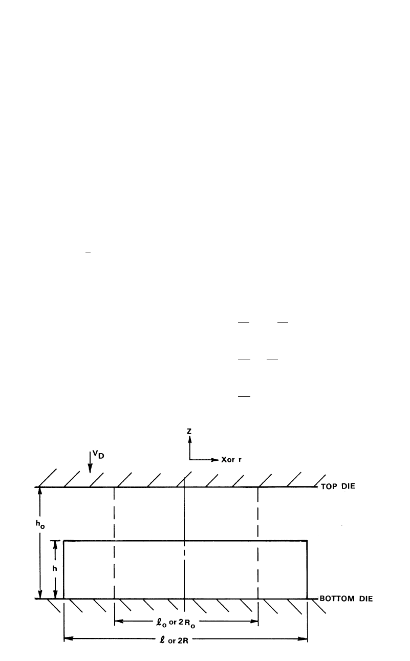
Methods of Analysis for Forging Operations / 93
Fig. 9.1 Changes in shape during upsetting. Plane strain (initial width ᐉ
o
and initial height h
o
) and axisymmetric (initial radius R
o
)
used successfully in simulating complex two-di-
mensional (2-D) and three-dimensional (3-D)
forging operations.
This chapter briefly discusses the slab, upper-
bound, and the finite element (FE) methods.
9.2 Slab Method of Analysis
The following assumptions are made in using
the slab method of analysis:
●
The deforming material is isotropic and in-
compressible.
●
The elastic deformations of the deforming
material and the tool are neglected.
●
The inertial forces are small and are ne-
glected.
●
The frictional shear stress, s, is constant at
the die/material interface and is defined as
s ⳱
f¯r ⳱ m¯r/3.
冪
●
The material flows according to the von
Mises rule.
●
The flow stress and the temperature are con-
stant within the analyzed portion of the de-
forming material.
The basic approach for the practical use of the
slab method is as follows:
1. Estimate or assume a velocity or metal flow
field.
2. For this velocity field, estimate the average
strains, strain rates, and temperatures within
each distinct time zone of the velocity field.
3. Thus, estimate an average value of the flow
stress, within each distinct zone of de-¯r,
formation.
4. Knowing and friction, derive or apply the¯r
necessary equations for predicting the stress
distribution and the forming load (in the
slab method) or the forming load and the
average forming pressure (in the upper-
bound method).
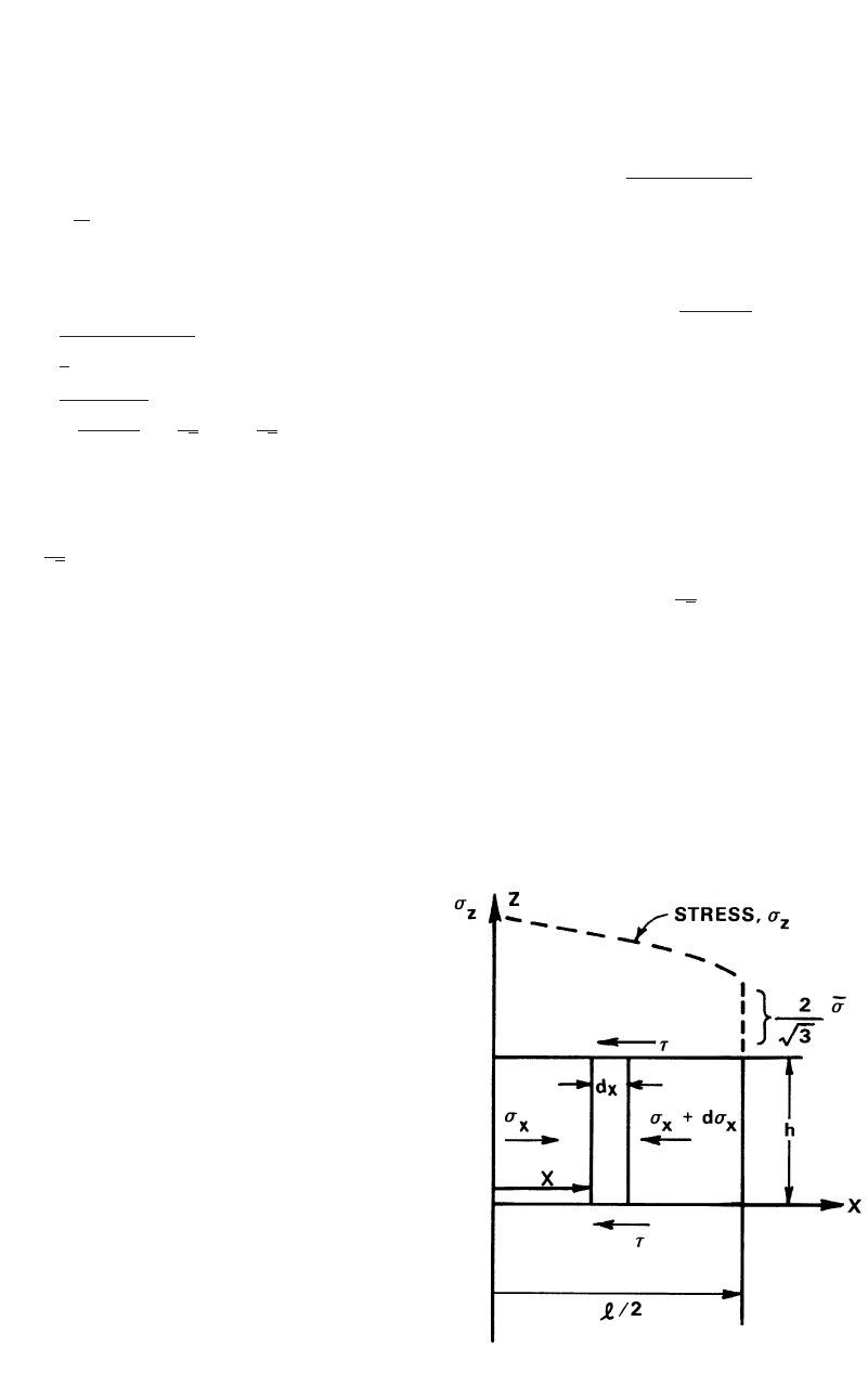
9.2.1 Application of Slab
Method to Plane-Strain Upsetting
The Velocity Field. In this case, deformation
is homogeneous and takes place in the x-z plane
(Fig. 9.1). The velocity field, with the velocities
in the x, y, and z directions, is defined as:
v ⳱ⳮV z/h; v ⳱ V x/h; v ⳱ 0 (Eq 9.1)
zDxDy
where V
D
is the velocity of the top die.
The strain rates are:
vV
zD
˙e ⳱⳱ⳮ (Eq 9.2a)
z
zh
vV
xD
˙e ⳱⳱⳱ⳮ˙e (Eq 9.2b)
xz
xh
v
y
˙e ⳱⳱0 (Eq 9.2c)
y
y
94 / Cold and Hot Forging: Fundamentals and Applications
Fig. 9.2
Equilibrium of forces in plane strain homogeneous
upsetting
It can be shown easily that the shear strain rates
are ⳱ 0.˙c ⳱ ˙c
xz yz
The strains are:
h
e ⳱ ln ; e ⳱ⳮe ; e ⳱ 0 (Eq 9.3)
zxzy
h
o
The effective strain rate is given by the equa-
tion:
2
222
˙
¯e ⳱ (˙e Ⳮ ˙e Ⳮ ˙e )
xyz
冪
3
22
˙e Ⳮ ˙e 22
xz
˙
¯e ⳱ 2 ⳱ |˙e | ⳱ |˙e | (Eq 9.4)
xz
冢冣
冪
3
33
冪冪
The effective strain is:
2
¯e ⳱ |e | (Eq 9.5)
z
3
冪
The slab method of analysis assumes that the
stresses in the metal flow direction and in the
directions perpendicular to the metal flow direc-
tion are principal stresses, i.e.:
r ⳱ r , r ⳱ r ; r ⳱ r (Eq 9.6)
z1x3y2
Plastic deformation/plastic flow starts when
the stresses at a given point in the metal reach a
certain level, as specified by a flow rule such as
the Tresca or von Mises rule discussed in Chap-
ter 5. Analysis of plastic deformation requires a
certain relationship between the applied stresses
and the velocity field (kinematics as described
by velocity, strain (e) and strain rate fields).(˙e)
Such a relation between the stresses (in principal
axes) and strain rates is given as follows:
˙e ⳱ k(r ⳮ r )
11m
˙e ⳱ k(r ⳮ r )
22m
˙e ⳱ k(r ⳮ r )
33m
where k is a constant and r
m
is the hydrostatic
stress.
These equations are called the plasticity equa-
tions. From these equations, for the plane strain
case one obtains:
˙e ⳱ ˙e ⳱ k(r ⳮ r ) ⳱ 0
2y 2 m
or
r ⳱ r (Eq 9.7)
2m
Per definition:
r Ⳮ r Ⳮ r
123
r ⳱
m
3
or, with Eq 9.7:
r Ⳮ r
13
r ⳱ r ⳱
m2
2
For plane strain, i.e., r
2
⳱ r
m
, the von Mises
rule gives:
222
3[(r ⳮ r ) Ⳮ (r ⳮ r ) ⳮ 0] ⳱ 2¯r
1m 3m
(Eq 9.8)
After simplification, the flow rule is:
2¯r
r ⳮ r ⳱ r ⳮ r ⳱ (Eq 9.9)
13zx
冷冷
3
冪
Estimation of Stress Distribution. In apply-
ing slab analysis to plane strain upsetting, a slab
of infinitesimal thickness is selected perpendic-
ular to the direction of metal flow (Fig. 9.2).
Assuming a depth of “1” or unit length, a force
balance is made on this slab. Thus, a simple
equation of static equilibrium is obtained
[Thomsen et al., 1965] [Hoffman et al., 1953].
Methods of Analysis for Forging Operations / 95
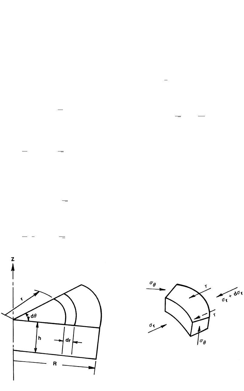
Fig. 9.3 Equilibrium of forces in axisymmetric homogeneous upsetting
Summation of forces in the X direction is zero
or:
F ⳱ r h ⳮ (r Ⳮ dr )h ⳮ 2sdx ⳱ 0
兺
xx x x
or
dr ⳱ⳮ2sdx/h
x
Thus, by integration one gets:
2s
r ⳱ⳮ x Ⳮ C
x
h
From the flow rule of plane strain, it follows
that:
2s 2
r ⳱ⳮ x Ⳮ C Ⳮ ¯r (Eq 9.10)
z
冷冷
h
3
冪
The constant C is determined from the boundary
condition at x ⳱ ᐉ/2, where r
x
⳱ 0, and, from
Eq 9.9:
2
r ⳱ ¯r
z
冷冷
3
冪
Thus:
2s ᐉ 2
r ⳱ⳮ ⳮx ⳮ ¯r (Eq 9.11)
z
冢冣
h2
3
冪
Equation 9.11 illustrates that the vertical
stress increases linearly from the edge (x ⳱
ᐉ/2) of Fig. 9.2 toward the center (x ⳱ 0). The
value of r
z
is negative, because z is considered
to be positive acting upward and the upsetting
stress is acting downward. Integration of Eq
9.11 gives the upsetting load.
In Eq 9.11, the frictional shear stress, s,is
equal to Thus, integration of Eq 9.11
m¯r/3.
冪
over the entire width, ᐉ, of the strip of unit depth
gives the upsetting load per unit depth:
2¯r mᐉ
L ⳱ 1 Ⳮ ᐉ
冢冣
4h
3
冪
9.2.2 Application of the Slab Analysis
Method to Axisymmetric Upsetting
Figure 9.3 illustrates the notations used in the
homogeneous axisymmetric upsetting. The anal-
ysis procedure is similar to that used in plane
strain upsetting.
Velocity Field. The volume constancy holds;
i.e., the volume of the material moved in the z
direction is equal to that moved in the radial di-
rection, or:
2
prV ⳱ 2prv h, or v ⳱ V r/2h
DrrD
In the z direction, v
z
can be considered to vary
linearly while satisfying the boundary condi-
tions at z ⳱ 0 and z ⳱ h. In the tangential di-

96 / Cold and Hot Forging: Fundamentals and Applications
rection, H, there is no metal flow. Thus, the ve-
locities are:
v ⳱ V r/2h; v ⳱ⳮV z/h; v ⳱ 0 (Eq 9.13)
rD z D H
In order to obtain the strain rate in the tan-
gential direction, it is necessary to consider the
actual metal flow since v
H
⳱ 0 and cannot be
used for taking a partial derivative. Following
Fig. 9.3, the increase in strain in the H direction,
i.e., the length of the arc, is given by:
(r Ⳮ dr)dH ⳮ rdH dr
de ⳱⳱(Eq 9.14)
H
rdH r
or the strain rate is
de dr 1 v V
H rD
˙e ⳱⳱ ⳱⳱ (Eq 9.14a)
H
dt dt r r 2h
The other strain rates are:
vV
zD
˙e ⳱⳱ⳮ (Eq 9.14b)
z
zh
vV
rD
˙e ⳱⳱⳱˙e (Eq 9.14c)
r H
r2h
1 v v
r
˙c ⳱Ⳮ⳱0 (Eq 9.14d)
rz
冢冣
2 z r
˙c ⳱ ˙c ⳱ 0 (Eq 9.14e)
HzrH
Thus, the effective strain rate is:
2
222
˙
¯e ⳱ (˙e Ⳮ ˙e Ⳮ ˙e ) ⳱ |˙e | (Eq 9.15)
H rz z
冪
3
The strains can be obtained by integrating the
strain rates with respect to time, i.e.:
tt
Vdt
D
e ⳱ ˙e dt ⳱ⳮ
zz
冮冮
tt
h
oo
or with ⳮdh ⳱ⳮV
D
dt:
h
dh h
e ⳱ⳮ⳱ⳮln (Eq 9.16a)
z
冮
h
hh
o
o
Similarly, the other strains can be obtained as:
1h e
z
e ⳱ e ⳱ ln ⳱ⳮ (Eq 9.16b)
H r
2h 2
o
In analogy with Eq 9.15, the effective strain is:
¯e ⳱ |e | (Eq 9.17)
z
The flow rule for axisymmetric deformation
is obtained by using a derivation similar to that
used in plane strain deformation. Because
, the plasticity equations give:˙e ⳱ ˙e
r h
r ⳱ r or r ⳱ r
r h 23
Thus, the von Mises flow rule for axisymmetric
upsetting is:
r ⳮ r ⳱ |¯r|orr ⳮ r ⳱ |¯r| (Eq 9.18)
12 zr
Estimation of Stress Distribution. The equi-
librium of forces in the r direction (Fig. 9.3)
gives [Thomsen et al., 1965] [Hoffman et al.,
1953]:
F ⳱ r (dh)rh ⳮ (r Ⳮ dr )
兺
rr r r
dh
(r Ⳮ dr)hdh Ⳮ 2r sin
h
2
hdr ⳮ 2srdhdr ⳱ 0 (Eq 9.19)
The angle dh is very small. Thus, with sin dh/2
⳱ dh/2, and after canceling appropriate terms,
Eq 9.19 reduces to:
dr 2s
r
ⳮr ⳮ r Ⳮ r ⳮ r ⳱ 0 (Eq 9.20)
r h
dr h
Since in axisymmetric deformation, ˙e ⳱ ˙e ,
r h
the plasticity equations give:
dr 2s
r
r ⳱ r ,or Ⳮ⳱0 (Eq 9.21)
r h
dr h
Integration gives:
2s
r ⳱ⳮ r Ⳮ C
r
h
The constant C is determined from the condition
that at the free boundary, r ⳱ R in Fig. 9.3, and
the radial stress r
r
⳱ 0. Thus, integration of Eq
9.21 gives:
2s
r ⳱ (r ⳮ R) (Eq 9.22)
r
h

Methods of Analysis for Forging Operations / 97
With the flow rule, Eq 9.22 is transformed
into:
2s
r ⳱ (r ⳮ R) ⳮ ¯r (Eq 9.23)
z
h
Equation 9.23 illustrates that the stress increases
linearly from the edge toward the center. The
upsetting load can now be obtained by integrat-
ing the stress distribution over the circular sur-
face of the cylindrical upset:
R
L ⳱ r 2prdr
z
冮
0
Considering that s ⳱ integration gives:m¯r/3,
冪
2mR
2
L ⳱ ¯rpR1Ⳮ (Eq 9.24)
冢冣
3h 3
冪
9.3 Upper Bound Method and
Its Application to
Axisymmetric Upsetting
9.3.1 Principles of the Method
This method can be used to estimate the de-
formation load and the average forming pres-
sure. For describing metal flow with the upper-
bound method, it is necessary to make the usual
assumptions, discussed earlier in the slab
method, as well as perform the following steps:
1. Describe a family of admissible velocity
fields (use parameters to be determined later);
these must satisfy the conditions of: incom-
pressibility, continuity, and velocity bound-
aries.
2. Calculate the energy rates of deformation, in-
ternal shear, and friction shear.
3. Calculate the total energy rate and minimize
it with respect to unknown parameters of ve-
locity field formulation.
The load is then obtained by dividing the energy
rate by the relative velocity between the die and
the deforming material.
The total energy rate, E
˙
T
, is given by E
˙
T
⳱
load ⳯ die velocity, or [Avitzur, 1968]:
˙˙˙˙
E ⳱ LV ⳱ E Ⳮ E Ⳮ E
TDDSF
or
˙
˙
E ⳱ ¯r ¯edV Ⳮ s|Dv|ds Ⳮ s vds
Tii
冮冮 冮
VSS SF
(Eq 9.25)
where E
˙
D
,E
˙
S
, and E
˙
F
are the energy rates for
deformation, internal shear, and friction, respec-
tively; L is the forming load; V is the volume of
deforming material; v is the relative velocity be-
tween two zones of material, when the velocity
field has internal shear surfaces; S indicates sur-
face (internal or at die/material interface); v
i
is
the die material interface velocity in the “i” por-
tion of the deforming material; s ⳱ and
¯r/3;
冪
s
i
⳱⳱interface shear stress at the “i”m¯r/3
冪
i
portion of the deforming material.
Based on limit theorems [Avitzur, 1968], the
load calculated with Eq 9.25 is necessarily
higher than the actual load and therefore repre-
sents an upper bound to the actual forming load.
Thus, the lower this upper bound load is, the
better the prediction. Often the velocity field
considered includes one or more parameters that
are determined by minimizing the total energy
rate with respect to those parameters. Thus, a
somewhat better upper-bound velocity field and
solution are obtained. In general, with an in-
creasing number of parameters in the velocity
field, the solution improves while the computa-
tions become more complex. Consequently, in
the practical use of the upper-bound method,
practical compromises are made in selecting an
admissible velocity field.
9.3.2 Application to Axisymmetric
Homogeneous Upsetting
The velocity field for homogeneous upsetting
is given by Eq 9.13 to 9.15. Thus, all the veloc-
ities and strain rates are known. Assuming a con-
stant flow stress, the deformation energy rate¯r,
is:
V
D
2
˙
˙
E ⳱ ¯r ¯edV ⳱ hpR¯r (Eq 9.26)
D
冮
v
h
E
˙
S
(internal shear energy rate) ⳱ 0, because
there are no internal velocity discontinuities in
the present homogeneous velocity field.
The friction energy rate is:
˙
E ⳱ 2 s vds
Fii
冮
SF
where v
i
is the radial velocity, given in Eq 9.13,
and ds ⳱ 2prdr. E
˙
F
includes the friction energies