Cold and Hot Forging: Fundamentals and Applications / Edited by Taylan Altan, Gracious Ngaile, Gangshu Shen
Подождите немного. Документ загружается.

172 / Cold and Hot Forging: Fundamentals and Applications
Fig. 14.18
Preforming, blocking, and finish forging opera-
tions for an example steel forging [Haller, 1971]
form allows the control of the volume distribu-
tion of the part during forging as well as control
over the material flow. The main objective of
preform design is to distribute the metal in the
preform in order to:
●
Ensure defect-free metal flow and adequate
die filling. Figure 14.16 shows how a defect
can form with insufficient volume distribu-
tion in an H-shaped cross section [Haller,
1971]
●
Minimize the amount of material lost as flash
●
Minimize die wear in the finish-forging cav-
ity by reducing the metal movement in this
operation
●
Achieve desired grain flow and control me-
chanical properties
The common practice in preform design is to
consider planes of metal flow, i.e., selected cross
sections of the forging (Fig. 14.17) [Altan et al.,
1973]. Understanding the principles of the ma-
terial flow during the forging operation can help
attain a better understanding of the design rules.
Any complex shape can be divided into axisym-
metric or plane-strain flow regions, depending
on the geometry in order to simplify the analy-
sis.
The example steel forging presented in Fig.
14.18 illustrates the various preforming opera-
tions necessary to forge the part shown [Haller,
1971]. The round bar from rolled stock is rolled
in a special machine called a reducer roller for
volume distribution, bent in a die to provide the
appropriate shape, blocked in a blocker die cav-
ity, and finish forged.
In determining the forging steps for any part,
it is first necessary to obtain the volume of the
forging based on the areas of successive cross
sections throughout the forging. The volume dis-
tribution can be obtained in the following man-
ner [Haller, 1971]:
1. Lay out a dimensioned drawing of the finish
configuration, complete with flash.
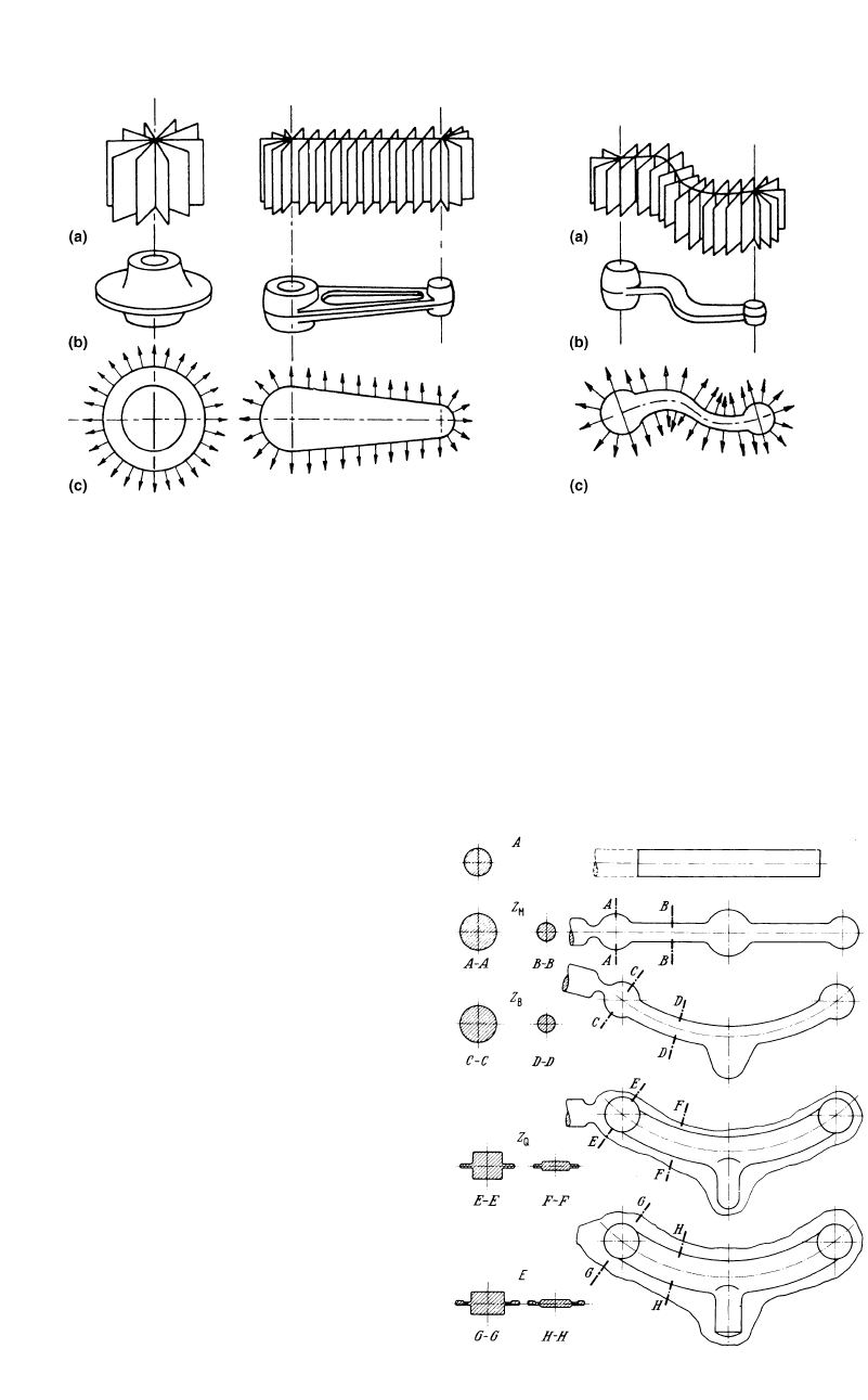
Fig. 14.17 Planes of metal flow. (a) Planes of flow. (b) Finished forged shapes. (c) Directions of flow [Altan et al., 1973]
Process Design in Impression-Die Forging / 173
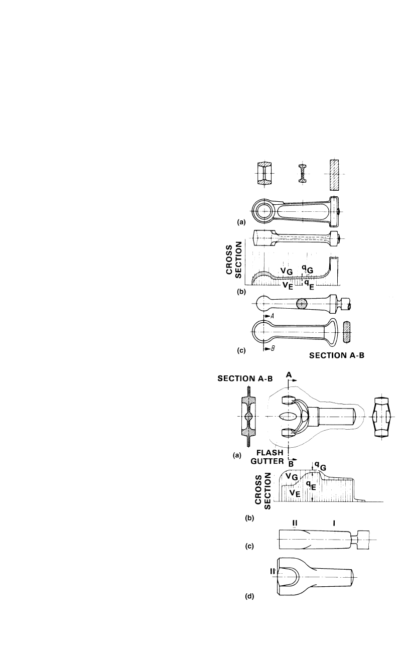
Fig. 14.19
Preform designs for two example parts. In both
examples, (a) forging, (b) cross-sectional area vs.
length, (c) and (d) ideal preform, V
E
and q
E
, volume and cross
section of the finish forging, and V
G
and q
G
, volume and cross
section of the flash [Haller 1971]
2. Construct a baseline for area determination
parallel to the centerline of the part.
3. Determine the maximum and minimum
cross-sectional areas perpendicular to the
centerline of the part.
4. Plot these area values at proportional dis-
tances from the baseline.
5. Connect these points with a smooth curve (in
instances where it is not clear how the curve
would best show the changing cross-sec-
tional areas, additional points should be plot-
ted to assist in determining a smooth repre-
sentation curve).
6. Above this curve, add the approximate area
of the flash at each cross section, giving con-
sideration to those sections where the flash
should be widest. The flash will generally be
of constant thickness but will be widest at the
narrower sections and smallest at the wider
sections (the proportional allowance for flash
is illustrated by the examples in Fig. 14.19).
7. Convert the minimum and maximum area
values to rounds or rectangular shapes having
the same cross-sectional area.
Figure 14.19 shows two examples of obtain-
ing a volume distribution through the above pro-
cedure. In both examples, (a) is the forging, (b)
is the cross-sectional area versus length, (c) and
(d) are the ideal preform, V
E
and q
E
are the vol-
ume and cross section of the finish forging, and
V
G
and q
G
are the volume and cross section of
the flash.
There are various methods of preforming i.e.,
for distributing the metal prior to die forging in
a blocker or finisher die [Altan et al., 1973,
Haller, 1971, and Lange et al., 1977]. In forging
steel parts, a correct preform can be designed by
using the following three general design rules
(these rules do not apply to forging nonferrous
materials) [Lange et al., 1977]:
●
The area of cross section of the preform ⳱
the area of cross section of the finished prod-
uct Ⳮ the flash allowance (metal flowing
into flash). Thus, the initial stock distribution
is obtained by determining the areas of cross
sections along the main axis of the forging.
●
All the concave radii, including the fillet ra-
dii, on the preform must be greater than the
corresponding radii on the finished part.
●
In the forging direction, the thickness of the
preform should be greater than that of the
finished part so that the metal flow is mostly
by upsetting rather than extrusion. During
the finishing stage, the material will then be
squeezed laterally toward the die cavity
without additional shear at the die/material
interface. Such conditions minimize friction
and forging load and reduce wear along the
die surfaces.
The application of these three design rules for
preforming of steel forgings is illustrated by ex-
amples shown in Fig. 14.20 for H-shaped cross
174 / Cold and Hot Forging: Fundamentals and Applications
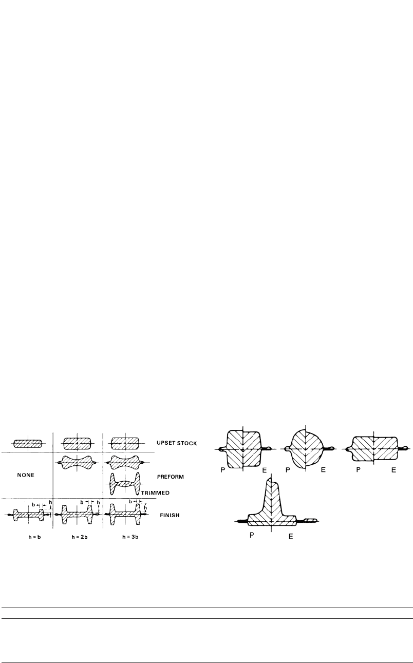
Fig. 14.21
The blocker and finish cross sections for various
shapes (P, preform; E, end) [Lange et al., 1977]
Fig. 14.20
Preforms for different H-shaped forgings [Lange
et al., 1977]
sections of various rib heights and in Fig. 14.21
for some solid cross sections [Lange et al.,
1977].
The preform is the shape of the billet before
the finish operation. In certain cases, depending
on the ratio of the height of the preform to its
width, there might be more than one preform
operation involved.
Preform design guidelines differ from mate-
rial to material. They are basically categorized
into the following three categories.
●
Carbon and low-alloy steel parts
●
Aluminum alloy rib-web-type parts
●
Titanium alloy rib-web-type parts
14.6.1 Guidelines for
Carbon and Low-Alloy Steels
In hammer forging of carbon or low-alloy
steels, the preform usually does not have flash.
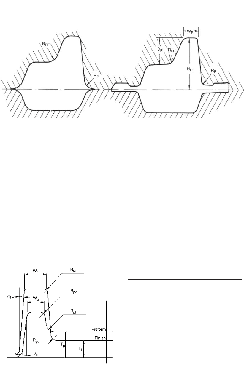
The blend-in radius (R
P
) of the preform at the
parting line is influenced by the adjacent cavity
depth (Table 14.2). In the preform, the fillet ra-
dius (R
PF
) between the web to a rib is larger than
that in the finish forging (R
FF
), especially when
the height of the rib over the web is larger than
the rib width, i.e., D
F
W
F
(Fig. 14.22).
14.6.2 Guidelines for Aluminum Parts
For rib-web-type aluminum alloy parts, the
recommended preform dimensions fall into the
following ranges given in Table 14.3. The pre-
form is usually designed to have the same draft
angles as the finish part. However, when very
deep cavities are present in the finisher die,
larger draft angles are provided in the preform.
A greater web thickness in the preform is se-
lected when the web area is relatively small and
when the height of the adjoining ribs is very
large. A comparison of the preform and the fin-
ished part is illustrated in Fig. 14.23.
14.6.3 Guidelines for Titanium Alloys
The guidelines for designing the titanium al-
loy preforms (Table 14.4) are similar to those
for the aluminum alloys.
14.6.4 Guidelines for H Cross Sections
Most of the parts that are closed-die forged
are H cross-section-type parts or they can be de-
composed into H cross sections. For this reason
it is good to have specific rules for these types
of cross sections. These rules are different for
different proportions in an H cross-section-type
part. The design guidelines for preform design
for rib-web-type sections must consider:
●
Different rib-height (D
F
) to rib-width (W
F
)
ratios
●
Different distances between the ribs (W
D
)
Table 14.2 Preform dimensions for carbon or low-alloy steels [Altan et al., 1973]
Dimensions of the finish forgings Dimensions of the preforms
Flash No flash
Blend-in radii (R
F
)R
P
艑 R
F
Ⳮ CorH
R
/6 R
P
H
R
/4
Fillet radii (R
FF
)R
PF
艑 1.2 R
FF
Ⳮ 0.125 in. (3.175 mm)
Depth of the cavity (H
R
), in. (mm) 0.4 (10) 0.4 to 1 (10 to 25) 1 to 2 (25 to 51) 2 (51)
Value of C, in. (mm) 0.08 (2.0) 0.12 (3.0) 0.16 (4.0) 0.2 (5.1)
Process Design in Impression-Die Forging / 175
Fig. 14.22 Preform and finish shape [Altan et al., 1973]
Table 14.3 Preform dimensions for aluminum
alloys [Altan et al., 1973]
Dimensions of the finish forgings Dimensions of the preforms
Web thickness (t
f
)T
p
艑 (1 to 1.5) • t
f
Fillet radii (R
ff
)R
pf
艑 (1.2 to 2) • R
ff
Corner radii (R
fc
)R
pc
艑 (1.2 to 2) • R
fc
Draft angle (␣
f
) ␣
p
艑 ␣
f
Ⳮ (2 to 5)
Width of the rib (W
f
)W
p
艑 W
f
ⳮ
1
⁄
32
in. (0.8 mm)
Fig. 14.23
Comparison of the preform and finished part for
a quarter of an H cross section [Altan et al.,
1973]
Table 14.4 Preform dimensions for titanium
alloys [Altan et al., 1973]
Dimensions of the
finish forgings Dimensions of the preforms
Web thickness (t
f
)T
p
艑 (1.5 to 2.2) • t
f
Fillet radii (R
ff
)R
pf
艑 (2 to 3) • R
ff
Corner radii (R
fc
)R
pc
艑 (2) • R
fc
Draft angle (␣
f
) ␣
p
艑 ␣
f
Ⳮ (3 to 5)
Width of the rib (W
f
)W
p
艑 W
f
ⳮ
1
⁄
16
to
1
⁄
8
in. (1.6 to 3.2 mm)
Height of the Rib (D
F
) 2 • Width of the
Rib (W
F
). For an H cross-section part in which
the rib height is smaller than two times the rib
width, the preform will have a rectangular shape
(Fig. 14.24). All one has to know is how to cal-
culate the overall width of the preform, B
P
, and
its height, H
P
. All the other parameters, such as
radii and the draft angle, will be set according
to the generic guidelines for different materials:
●
The overall width of the preform (B
P
) is de-
termined in terms of the finish cavity width
(B
F
). It is expressed as:
B ⳱ B ⳮ(0.08 to 0.4)
PF
●
The height of the preform (H
P
) is obtained
after calculating the preform width by divid-
ing the surface area (SA) of the finish cross
section by the preform width:
H ⳱ (SA Ⳮ flash)/B
PP
Flash ⳱ 5 to 15% of SA
Height of the Rib (D
F
) 2 • Width of the
Rib (W
F
). For an H cross-section part in which
the rib height is larger than two times the rib
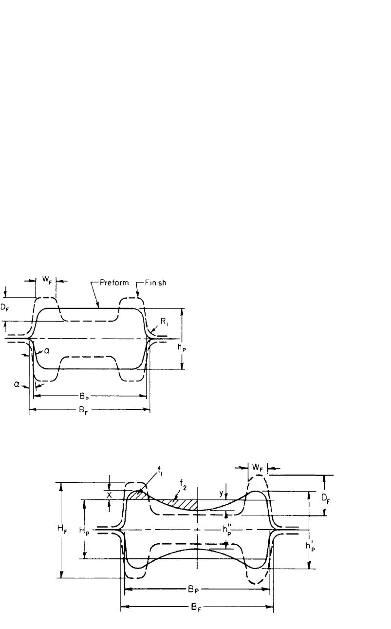
176 / Cold and Hot Forging: Fundamentals and Applications
Fig. 14.24
Preform shape when D
F
2 • W
F
[Bruchanov
et al., 1955]
width, the preform has a trapezoidal shape. The
parameters to set are overall width of the pre-
form (B
P
), height of the preform (H
P
), additional
rib height (x), and thinning of the web portion
(y). All the other parameters, such as radii and
the draft angle, will be set according to the ge-
neric guidelines for different materials:
●
The overall width of the preform (B
P
) is de-
termined in terms of the finish cavity width
(B
F
). It is expressed as:
B ⳱ B ⳮ(0.08 to 0.4)
PF
●
The height of the preform (H
P
) is obtained
after calculating the preform width by divid-
ing the surface area of the finish cross section
by the preform width:
H ⳱ (SA Ⳮ flash)/B
PP
Flash ⳱ 5 to 15% of SA
●
Additional rib height (x): The preform for
this cross section is considered to have a
trapezoidal form (Fig. 14.25). The necessary
additional rib height (x) is determined by:
x ⳱ 0.25 (H ⳮH)
FP
●
Thinning of the web portion (y): Once the
preform height and the additional rib height
are determined, the thinning of the web por-
tion is calculated by setting the areas f
1
⳱ f
2
(Fig. 14.25), where the web and the rib are
blended together with large radii.
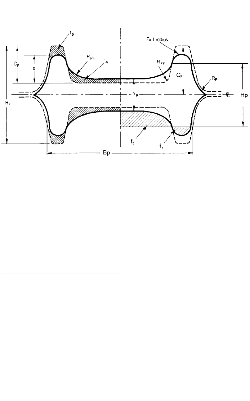
Distance between Ribs (W
D
) Very Large.
For an H cross-section part in which the distance
between the ribs is very large, the preform has
a trapezoidal shape (Fig. 14.26). The parameters
to be set are overall width and height of the pre-
form (B
P
and H
P
), rib height (x), fillet and flash
radius (R
PF
and R
P
), and preform thickness (H
P
).
All the other parameters, such as radii and the
draft angle, will be set according to the generic
guidelines for different materials:
●
Overall width and height of the preform:
B ⳱ B ⳮ(0.08 to 0.4)
PF
H ⳱ (SA Ⳮ flash)/B
PP
Flash ⳱ 5 to 15% of SA
●
Rib height (x): The preform for this cross
section is assumed to have a trapezoidal
form. The surface area f
2
can be significantly
larger than the surface area f
1
(Fig. 14.26).
The required rib height is determined by the
relation:
x ⳱ (0.6 to 0.8) D
F
Fig. 14.25 Preform shape when D
F
2 • W
F
[Bruchanov et al., 1955]
Process Design in Impression-Die Forging / 177
Fig. 14.26 Preform design when the distance between the ribs is very large [Bruchanov et al., 1955]
●
Fillet and flash radii (R
PF
,R
P
):
R ⳱ 1.2 R Ⳮ 0.125 in. (3.175 mm)
PF FF
R 艑 R Ⳮ C
PF
●
Preform thickness (H
P
): The preform thick-
ness is determined by using the condition
that the volume represented by f
4
should be
larger than the volume represented by f
3
by
the excess of the flash material (Fig. 14.26).
APPENDIX A
Example: Prediction of
Load for Forging of a
Connecting Rod
A.1 Introduction
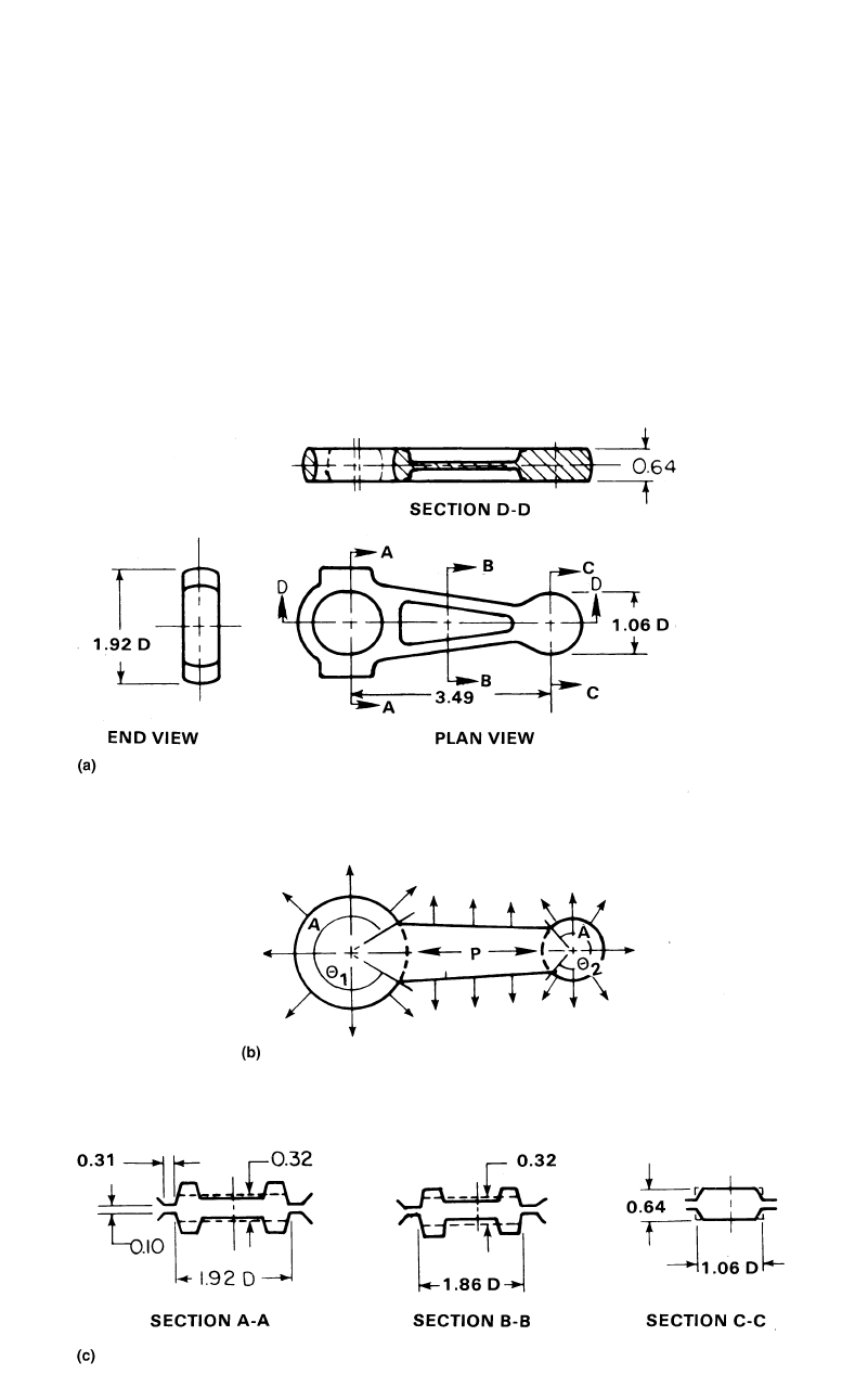
A connecting rod (Fig. A.1) was selected as
a component to be used for practical evaluation
of the calculations described in section 14.5.2,
“Simplified Slab Method to Estimate Forging
Load,” in this chapter. The part was forged in a
500 ton mechanical press, and the measured
loads were compared with the results obtained
from computer-aided analysis as well as with re-
sults from the simplified slab method.
Three representative cross sections of the con-
necting rod were chosen for the estimation of
the forging load (Fig. A.1). All the cross sections
had the same flash dimensions, namely, blocker:
0.1 in. (2.5 mm) thick by 0.31 in. (7.9 mm) wide;
finish: 0.06 in. (1.5 mm) thick by 0.31 in. (7.9
mm) wide. These dimensions were the dimen-
sions of the flash lands in the dies. The values
of flash thickness used in the forging load esti-
mations were those actually measured on the
forged parts. All the cavity cross sections were
approximated as rectangles, as shown in Fig.
14.15 and A.1. The dimensions of the rectangles
(in inches) used for load estimation were:
●
Section A-A:
Blocker: r ⳱ 0.96, H ⳱ 0.32
Finish: L ⳱ 0.2, H ⳱ 0.18
●
Section B-B:
Blocker: L ⳱ 0.93, H ⳱ 0.32
Finish: L ⳱ 0.95, H ⳱ 0.18
●
Section C-C:
Blocker: r ⳱ 0.53, H ⳱ 0.64
Finish: r ⳱ 0.55, H ⳱ 0.59
During finish forging, in order to reduce the
excessive load resulting from forging a very thin
web, the central portion of cross-section A-A
was relieved. Hence, to estimate the load in this
cross section, only one-half of the section was
considered and was treated as a plane-strain
178 / Cold and Hot Forging: Fundamentals and Applications
Fig. A.1 (a) Geometry of the connecting rod. (b) Directions of metal flow. (c) Representative sections and their simplification
cross section of a length equal to the average
circumference of the lower boss of the connect-
ing rod.
A.2 Estimation of the Flow Stress
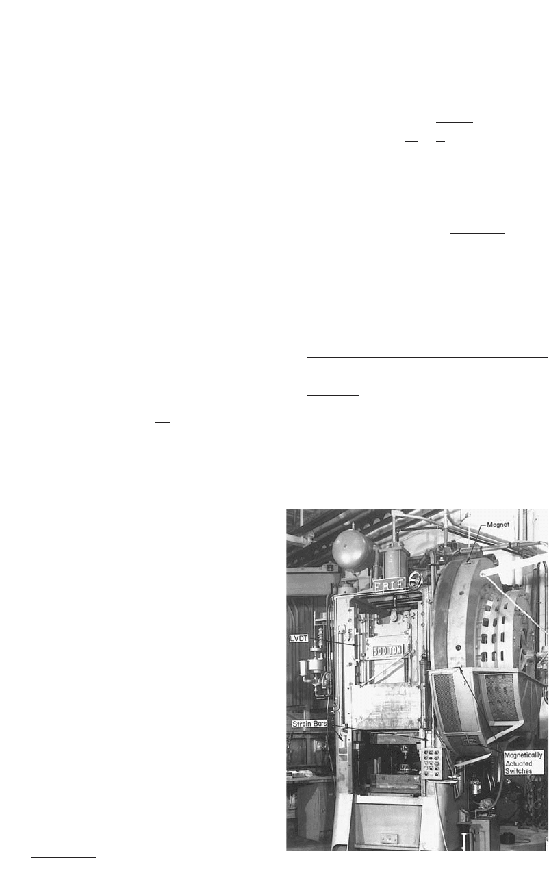
The forging trials were conducted in a me-
chanical press with a stroke of 10 in. (25.4 cm)
and a speed of 90 strokes per minute (Fig. A.2).
The blocker and finish dies were mounted side
by side on the press bolster (Fig. A.3). Both dies
were heated to approximately 350 F (175 C).
AISI type 1016 steel billets were heated to 2100
F (1150 C) prior to blocker forging. The tem-
perature of the billet prior to finish forging, as
measured during the trial runs, was approxi-
mately 1950 F (1065 C). Thus, some cooling
occurred during forging in the blocker cavity
and transfer into the finisher.
The flow stress is a function of the strain,
strain rate, and temperature that exist at a given
Process Design in Impression-Die Forging / 179
Fig. A.2
The 500 ton mechanical forging press used for forg-
ing trials
time during the deformation process and can be
expressed approximately as:
m
˙
r ⳱ C.¯e (Eq A.1)
The values of C and m for the material used
for the trials are given in Table A.1. These values
vary significantly with temperature. Hence, in
order to estimate the flow stress accurately, the
temperature of the deforming material should be
known. The temperature of the stock at the end
of the forging stroke depends on the stock tem-
perature, die temperature, speed of deformation,
and frictional conditions. Further, the tempera-
ture varies across the forging due to die chilling
and due to heat generation by friction and de-
formation. However, if the temperature gradient
is neglected and the forging is considered to be
a thin plate of uniform temperature cooled sym-
metrically from both sides, the average tempera-
ture of the forging in the cavity or in the flash
can be expressed as follows:
␣T
h ⳱ h Ⳮ (h ⳮ h ) exp ⳮ (Eq A.2)
1s1
冢冣
cqt
As an example, consider cross-section A-A of
the blocker dies in Fig. A.1:
●
h
1
(initial die temperature) ⳱ 350 F (175
C)
●
h
s
(initial stock temperature) ⳱ 2100 F
(1150 C)
●
␣ (heat-transfer coefficient) ⳱ 0.0039 Btu/
in.
2
/F (3.1889 W/m
2
-K) (estimated from
values obtained from the forging of steel)
●
t (average forging or plate thickness) ⳱ 0.32
in. (8.1 mm)
●
c (specific heat of the billet material) ⳱
0.108 Btu/lb/F (452 J/kg-K)
●
q (density of the billet material) ⳱ 0.285 lb/
in.
3
(7.89 g/cm
3
)
To estimate the duration of contact, the aver-
age ram velocity during forging should be
known. This velocity is half of the velocity of
the ram when it touches the billet. In this case,
the billet has round sections with an average di-
ameter of 0.75 in. (19 mm). The average thick-
ness of the blocker is 0.32 in. (8.1 mm). Hence,
the average distance of the ram from the bottom
dead center (BDC) position during forging is:
0.75 ⳮ 0.32
w ⳱⳱0.125 in. (3.175 mm)
2
(Eq A.3)
Thus, the ram velocity with respect to the ram
location (w) before BDC obtained from the kin-
ematics of the crank slider mechanism is:
pnS
V ⳱ w ⳮ 1
冪
30 w
The mechanical press used for these trials has
a stroke of 10 in. (25.4 cm) and a speed of 90
rpm. Hence:
p ⳯ 90 10
V ⳱ 0.215 ⳮ 1
冪
30 0.215
V ⳱ 13.67 in./s (0.35 m/s)
The duration of contact, T, is:
(Average billet thickness) ⳮ (Average forging thickness)
T ⳱
Average ram velocity
0.75 ⳮ 0.32
⳱⳱0.0315 s
13.67
The values of T can also be obtained from the
load or stroke versus time curve similar to the
one in Fig. A.4. The instantaneous average forg-
ing temperature is:
180 / Cold and Hot Forging: Fundamentals and Applications
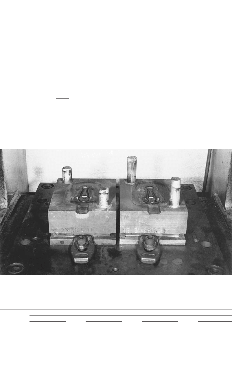
Fig. A.3 Blocker and finish forging dies as mounted on the bolster of the mechanical press
Table A.1 Summary of C (ksi) and m values describing the flow stress relation r ⴔ for AISI
m
˙
C.¯e
1016 steel at various temperatures
Value of C or m at a temperature of, F(C)
1650 (900) 1830 (1000) 2010 (1100) 2190 (1200)
Strain C m C m C m C m
0.05 11.8 0.133 10.7 0.124 9.0 0.117 6.4 0.150
0.1 16.5 0.099 13.7 0.099 9.7 0.130 7.1 0.157
0.2 20.8 0.082 16.5 0.090 12.1 0.119 9.1 0.140
0.3 22.8 0.085 18.2 0.088 13.4 0.109 9.5 0.148
0.4 23.0 0.084 18.2 0.098 12.9 0.126 9.1 0.164
0.5 23.9 0.088 18.1 0.109 12.5 0.141 8.2 0.189
0.6 23.3 0.097 16.9 0.127 12.1 0.156 7.8 0.205
0.7 22.8 0.104 17.1 0.127 12.4 0.151 8.1 0.196
AISI type 1016 steel (composition: 0.15 C, 0.12 Si, 0.68 Mn, 0.034 S, 0.025 P) in the hot rolled and annealed condition
h ⳱ 350 Ⳮ (2100 ⳮ 350)
(0.0039) (0.0315)
exp ⳮ
冢冣
(0.108) (0.285) (0.32)
⳱ 2078.3 F (1136.8 C)
The temperature increase due to deformation
is given by:
A¯r ¯e
aa
h ⳱
d
cq
where, in addition to the symbols previously de-
fined, h
d
is the temperature increase due to de-
formation; A is a factor used to convert me-
chanical energy to heat energy (A ⳱ 1.07 ⳯
10
ⳮ7
Btu/in.-lb) (9.798 J/m-kg); is the aver-¯r
a
age flow stress in the material (18,000 psi, or
124 MPa, assumed); and is the average strain,¯e
a
estimated from the initial and final thickness:
Initial thickness 0.75
¯e ⳱ ln ⳱ ln ⳱ 0.85
a
冢冣
Final thickness 0.32
Hence:
h ⳱ 53.2 F (11.8 C)
d
Ignoring the heat gain due to friction, the av-
erage temperature in the cavity of the blocker
die is:
h ⳱ h Ⳮ h ⳱ 2078.3 Ⳮ 53.2
cb d
⳱ 2131.5 F (1166.4 C)

Process Design in Impression-Die Forging / 181
Table A.3 Estimated loads in different cross
sections of the connecting rod forging
Loads in section, lb Total
Forging A-A B-B C-C lb Tons
Blocker 337,214 196,998 89,285 623,497 311.7
Finish 407,234 285,509 123,947 816,690 408.3
Table A.2 Estimated flow stresses in different
cross sections of the connecting rod forging
shown in Fig. A.1
Stock/
blocker
temperature
Flow stress in section,
psi (MPa)
Forging F C A-A B-B C-C
Blocker 2100 1150 18,000 (124) 17,000 (117) 16,300 (112)
Finish 1950 1065 22,000 (152) 21,600 (149) 20,200 (139)
From Table A.1, the values of C and m for a
temperature of 2130 F (1165 C) and strain of
0.85 are calculated by linear interpolation as
C ⳱ 9.8 ⳯ 10
3
and m ⳱ 0.187.
The average strain rate in the deforming ma-
terial is given by:
Velocity 13.67
˙
¯e ⳱⳱
Average thickness (0.75 Ⳮ 0.32)/2
⳱ 25.55/s
Using Eq A.1, the average flow stress is:
3 0.187
¯r ⳱ 9.8 ⳯ 10 ⳯ 25.55
⳱ 17,964 psi (124 MPa)
This is the value of the flow stress in the cav-
ity of the section A-A in the blocker shape. Sim-
ilarly, the corresponding values of flow stress for
other sections are given in Table A.2.
A.3 Estimation of the Friction Factor
The frictional shear stress is given by:
m¯r
s ⳱
3
冪
The value of m varies between 0.25 and 0.4 for
most hot steel forging operations. The simplified
model assumes that metal flow occurs by sliding
the entire die/material interface. In reality, how-
ever, the metal deforms by sliding along the web
surfaces, but internal shearing is inevitable in the
rib regions. Hence, to assume a nominal average
m value of 0.4, which is usual for sliding sur-
faces in forging, would be unrealistic. In the
present case, the length of the rib sections is al-
most equal to that of the web regions in cross-
sections A-A and B-B. Hence, considering a
weighted average, the values for m are chosen
to be 0.7 for sections A-A and B-B and 0.4 for
section C-C of both blocker and finish forgings.
A.4 Estimation of the Forging Load
The average length of plane-strain cross-sec-
tion B-B for both blocker and finish forgings is
2 in. (5 cm). Substituting the appropriate values
in Eq 14.8 to 14.11, the loads were estimated for
the cross sections as shown in Table A.3.
A.5 Comparison of Predictions with
Data from Actual Forging Trials
To evaluate the accuracy of the simplified
forging load estimation procedure, forging trials
were conducted using a 500 ton Erie scotch-
Fig. A.4
Load and displacement versus time for a forging
operation
Table A.4 Summary and comparison of forging
loads (tons)
Forging Simple analysis Experimental results
Blocker 311.7 320.67
Finish 408.3 425.00