Cold and Hot Forging: Fundamentals and Applications / Edited by Taylan Altan, Gracious Ngaile, Gangshu Shen
Подождите немного. Документ загружается.

182 / Cold and Hot Forging: Fundamentals and Applications
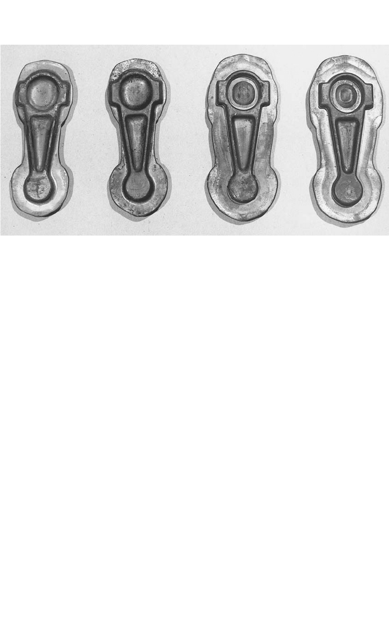
Fig. A.5 Parts that were blocker and finish forged in forging trials
yoke-type mechanical press. Both the blocker
and finisher dies were mounted side by side on
the press bolster. The dies were lubricated by
spraying with Acheson’s Delta-forge 105 (Ach-
eson Colloids Co.). The billets were heated in
an induction coil to 2100 F (1150 C). The dies
were heated to 350 F (175 C) by infrared gas-
fired burners. A typical load and displacement
recording is shown in Fig. A.4. The displace-
ment curve shows the position of the ram as a
function of time. It is observed that the forging
load starts increasing when the upper die con-
tacts the workpiece. The entire forging operation
takes place in less than 100 ms. Example forg-
ings are shown in Fig. A.5.
The forging loads, measured in experiments
and predicted by the simplified slab method, are
compared in Table A.4. The experimental values
represent averages of several measurements. It
can be seen that the results of the simplified anal-
ysis are within practical engineering accuracy.
For simple to moderately complex forgings, this
analysis can be used effectively for die material
selection and for press selection. However, it
should be noted that the accuracy of the final
results depends largely on proper estimation of
the flow stress and frictional shear factor. Some
experience and knowledge of forging analyses
is necessary to make these estimates with ac-
ceptable accuracy. If the capabilities of a high-
speed computer are available, then detailed cal-
culations of flow stress, forging stress, and
forging load can be made accurately.
REFERENCES
[Altan et al., 1973]: Altan, T., Boulger, F.W.,
Becker, J.R., Akgerman, N., Henning, H.J.,
Forging Equipment, Materials and Practices,
Batelle, 1973.
[Altan et al., 1983]: Altan, T., Oh, S.-I., Gegel,
H.L., Metal Forming Fundamentals and Ap-
plications, American Society for Metals,
1983.
[Bruchanov et al., 1955]: Bruchanov, A.N., and
Rebelski, A.V., Closed-Die Forging and
Warm Forging, Verlag Technik, 1955 (Ger-
man translation from Russian).
[Haller, 1971]: Haller, H.W., Handbook of Forg-
ing, Carl Hanser Verlag, 1971 (in German).
[Lange et al., 1977]: Lange, K., and Meyer-
Nolkemper, H., Closed-Die Forging,
Springer-Verlag, 1977 (in German).
[Neuberger et al., 1962]: Neuberger, F., and
Pannasch, S., “Material Consumption in Die
Forging of Steel,” Fertiegungstechnik und Be-
trieb, Vol. 12, 1962, p 775–779 (in German).
[Sabroff et al., 1968]: Sabroff, A.M. et al.,
Forging Materials and Practices, Reinhold,
1968.
[Spies, 1959]: Spies, K., “Preforming in Forging
and Preparation of Reducer Rolling,” Doc-
toral dissertation, University of Hannover,
1959.
[Subramanian et al., 1980]: Subramanian,
T.L., and Altan, T., “Practical Method for Es-
timating Forging Loads with the Use of a Pro-

Process Design in Impression-Die Forging / 183
grammable Calculator,” Journal of Applied
Metalworking, Vol. 1, No. 2, Jan. 1980, p 60.
[Teterin et al., 1968]: Teterin, G.P., and Tar-
novskij, I.J., “Calculation of Plastic Dimen-
sions in Forging Axisymmetric Parts in
Hammers,” Kuznec hno-Stampo vochnoe Proiz-
vodstvo, Vol 5, 1968, p 6 (in Russian).
[Vasquez et al., 2000]: Vasquez, V., and Altan,
T., “New Concepts in Die Design—Physical
and Computer Modeling Applications,” Jour-
nal of Materials Processing Technology, Vol.
98, 2000, p 212–223.
[Vieregge, 1968]: Vieregge, K., “Contribution
to Flash Design in Closed Die Forging,” Doc-
toral dissertation, Technical University of
Hannover, 1969.
SELECTED REFERENCES
●
[Brucelle et al., 1999]: Brucelle, O., and
Bernhart, G., “Methodology for Service Life
Increase of Hot Forging Tools,” Journal of
Material, Processing Technology, Vol. 87,
1999, p 237.
●
[Feldman, 1977]: Feldman, H.D., Cold Ex-
trusion of Steel, Merkblatt 201, Du¨seldorf,
1977.
●
[Jenkins et al., 1989]: Jenkins, B.L., Oh,
S.I., Altan, T., “Investigation of Defect For-
mation in a 3-Station Closed Die Forging
Operation,” CIRP Annals, Vol. 381, p 243.
●
[Sagemuller, 1968]: Sagemuller, F., “Cold
Impact Extrusion of Large Formed Parts,”
Wire, No. 95, June, 1968, p. 2.
●
[Shirgaokar et al., 2002]: Shirgaokar, M.,
Ngaile, G., Altan, T., “Multi-Stage Forging
Simulations of Aircraft Components,” ERC/
NSM-02-R-84, Engineering Research Cen-
ter for Net Shape Manufacturing, 2002.
●
[Snaith et al., 1986]: Snaith, B., Probert,
S.D., O’Callaghan, P.W., “Thermal Resis-
tances of Pressed Contacts,” Appl. Energy,
Vol. 22, 1986, p 31–84.

CHAPTER 15
A Simplified Method to
Estimate Forging Load in
Impression-Die Forging
Hyunjoong Cho
15.1 Introduction
In hot impression-die forging, forging load
and die stresses are important variables that af-
fect die life and determine the selection of press
capacity. During the die design and process
planning stage, it is necessary to estimate these
variables to avoid unexpected die failure and
provide for necessary forging load to fill the die
cavity.
Forging load may be estimated by experience-
based values, i.e., by multiplying the plan area
of the forging with an empirical pressure value,
for example, 60 to 100 ksi (415 to 690 MPa) for
forging steels and 20 to 30 ksi (140 to 205 MPa)
for forging aluminum alloys, where higher val-
ues are used for thinner forgings and stronger
alloys.
The forging load and die stresses may be cal-
culated using finite-element analysis that re-
quires a rather sophisticated software package,
elaborate input data preparation, and consider-
able computer time. Therefore, it is often desir-
able to use a simple method for making quick
estimates by using the so called “slab method”
of analysis. This method takes into account the
effects of material properties, friction and heat
transfer at die/material interface, press ram
speed, flash dimensions, forging geometry, and
billet and die temperatures.
This method may help the designer to under-
stand the effects of several forging parameters,
such as flash dimensions, forging temperature,
and friction (lubrication) on the forging load.
For example, if the effect of flash dimensions on
the forging load is known, then it is possible to
reduce the forging pressure, within limits, by in-
creasing the flash thickness or reducing the flash
width. The effect of stock temperature on the
forging load, if it is quantitatively known, can
assist in optimizing the forging conditions. In
some instances, it may be possible to forge at
lower stock temperatures. As a result, heating
costs and scale formation can be reduced.
15.2 Effect of Process
Parameters on Forging Load
During the forging process, metal flow, die
fill, and forging load are largely determined by
the flow stress of the forging materials, the fric-
tion and cooling effect at the die/material inter-
face, and the complexity of the forging shape.
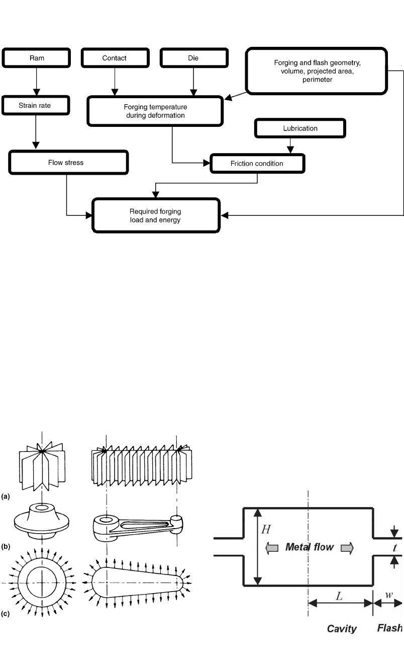
The interrelationships of the most significant
forging variables are illustrated in the block di-
agram in Fig. 15.1.
For a given part, the factors that affect the
forging load, briefly discussed in Fig. 15.1, were
discussed in detail in Chapter 14, “Process De-
sign in Impression-Die Forging.” The factors in-
clude:
●
The flow stress of the forged material as
function of strain (or amount of deforma-
tion), strain rate (rate of deformation), and
forging temperature
Cold and Hot Forging Fundamentals and Applications
Taylan Altan, Gracious Ngaile, Gangshu Shen, editors, p185-192
DOI:10.1361/chff2005p185
Copyright © 2005 ASM International®
All rights reserved.
www.asminternational.org
186 / Cold and Hot Forging: Fundamentals and Applications
Fig. 15.1 Interaction of significant variables in closed-die forging process [Nagpal et al., 1975]
●
Friction and heat transfer at the part/die in-
terface
●
Geometric complexity of the part and the
number of forging operations used (pre-
blocker, blocker, and finisher)
●
Flash design, flash thickness and width (or
flash land)
15.3 Methods for Load Estimation
In impression-die forging, the forging load is
the maximum at the end of the forging stroke.
As discussed in Chapter 14, “Process Design in
Impression-Die Forging,” four broadly defined
methods are used in estimating this maximum
load in hot forging.
●
Applied experience: The load is estimated
based on available data from previous forg-
ing of similar parts. These estimations are
very conservative and lead to significant er-
rors.
●
Empirical methods: Use simple empirical
formulas and graphs or monographs to esti-
mate the load for simple forging operations.
These methods are quick but limited in their
accuracy and are not sufficiently general to
predict forging load for a variety of parts and
materials.
●
Analytical methods: A forging is viewed as
being composed of several unit components.
Fig. 15.2
Planes and directions of metal flow for two simple
shapes. (a) Planes of flow. (b) Finish forging. (c)
Directions of flow [Altan et al., 1983]
Fig. 15.3 Schematic of simple impression-die forging
A Simplified Method to Estimate Forging Load in Impression-Die Forging / 187
Forces and stresses are calculated for every
unit and then added together to calculate the
total forging load and stresses. The slab
method is the most widely known technique
to perform this type of analysis. It is suc-
cessfully used for predicting forging loads
and stresses with acceptable engineering ac-
curacy.
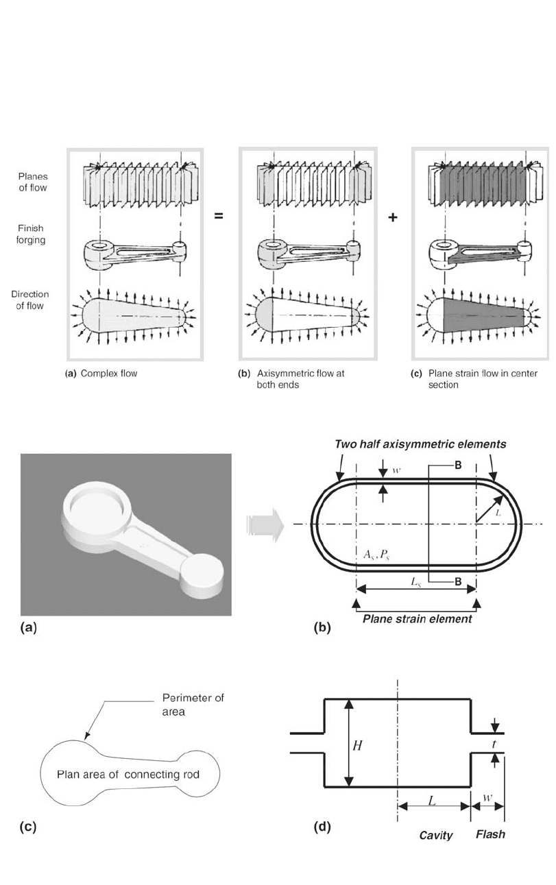
Fig. 15.4 Approximate load calculation for a complex part
Fig. 15.5
Transformation of a complex forging part into a simplified model. (a) Connecting rod (example of complex forging). (b)
Simplified model of the actual forging for forging load estimation [Mohammed et al., 1999]. (c) Plan area of connecting
rod and perimeter of plan area. (d) Cross section of simplified model (section B-B)
188 / Cold and Hot Forging: Fundamentals and Applications
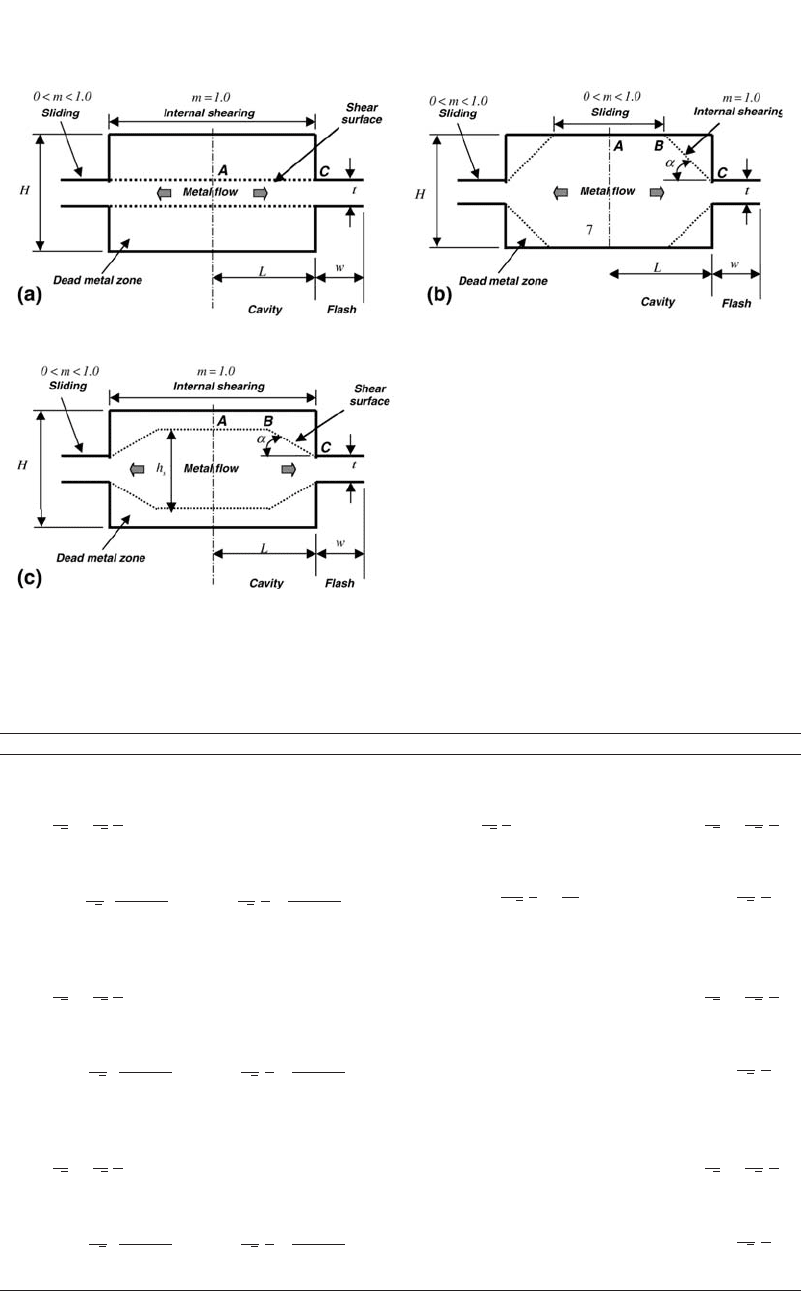
Fig. 15.6
Possible modes of metal flow at the end of forging stroke in impression-die forging. (a) Fictitious disk shearing. (b) Sliding
in the central portion of the cavity. (c) Complete shearing in the cavity
Table 15.1 Derived equations for load calculation
Flash load Cavity load Stress at the cavity entrance
Fictitious disk shearing
Plane strain
2mw
P ⳱ 2 Ⳮ w¯r
ff
冢冣
t
33
冪冪
¯r L
c
P ⳱ 2 Ⳮ r L
cce
冢冣
t
3
冪
22mw
r ⳱Ⳮ ¯r
ce f
冢冣
t
33
冪冪
Axisymmetric
33 22
2m R ⳮ L2mRRⳮ L
P ⳱ 2p ¯r ⳮⳭ1 Ⳮ
ff
冢冢 冣冢 冣冢 冣冣
3t t 2
33
冪冪
¯r L r
cce
2
P ⳱ 2pL Ⳮ
c
冢冣
t2
33
冪
2m w
r ⳱ 1 Ⳮ ¯r
ce f
冢冣
t
3
冪
Sliding in the cavity center
Plane strain
2mw
P ⳱ 2 Ⳮ w¯r
ff
冢冣
t
33
冪冪
P ⳱ 2(K ¯r t Ⳮ r L)
cpcce
22mw
r ⳱Ⳮ ¯r
ce f
冢冣
t
33
冪冪
Axisymmetric
33 22
2m R ⳮ L2mRRⳮ L
P ⳱ 2p ¯r ⳮⳭ1 Ⳮ
ff
冢冢 冣冢 冣冢 冣冣
3t t 2
33
冪冪
22
P ⳱ (K ¯r t Ⳮ pr L)
cac ce
2m w
r ⳱ 1 Ⳮ ¯r
ce f
冢冣
t
3
冪
Complete shearing in the cavity
Plane strain
2mw
P ⳱ 2 Ⳮ w¯r
ff
冢冣
t
33
冪冪
P ⳱ 2(K ¯r t Ⳮ r L)
cpscce
22mw
r ⳱Ⳮ ¯r
ce f
冢冣
t
33
冪冪
Axisymmetric
33 22
2m R ⳮ L2mRRⳮ L
P ⳱ 2p ¯r ⳮⳭ1 Ⳮ
ff
冢冢 冣冢 冣冢 冣冣
3t t 2
33
冪冪
22
P ⳱ (K ¯r t Ⳮ pr L)
casc ce
2m w
r ⳱ 1 Ⳮ ¯r
ce f
冢冣
t
3
冪
Note: The factors K
p
,K
a
,K
ps
, and K
as
are determined from L/t and H/t ratios.
A Simplified Method to Estimate Forging Load in Impression-Die Forging / 189
●
Numerical methods: The finite-element
method (FEM) is the most widely used
method in this field. The major advantage of
this method is its ability to generalize its ap-
plicability to various problems with little re-
striction on workpiece geometry. The FEM
is able to analyze metal flow during hot forg-
ing and is able to predict instantaneous
strains, stresses, and temperatures within the
deforming metal. The disadvantage of the
FEM is a large amount of computation time
and expensive system requirements, depend-
ing on the problem.
The advantage of the slab method is that a
complex forging can be divided into basic de-
formation units or blocks, and these could be
analyzed separately. Then, by putting the defor-
mation units together, loads for any complex
shape forging can be determined. Metal flow for
the deformation units is assumed to be either
axisymmetric or plane strain. The plane-strain
flow occurs in relatively long forgings where the
deformation along the length is relatively small
and can be neglected. Axisymmetric flow is en-
countered in round forgings and at the end of
long forging where the metal flows radially to-
ward the flash. Figure 15.2 shows examples of
plane-strain and axisymmetric flow in complex
forgings.
Even though the slab method cannot be as ac-
curate as the FEM because of the assumptions
made in developing the mathematical approach,
it is still attractive because it does not require
considerable computation time and does not re-
quire training for the user. In addition, the slab
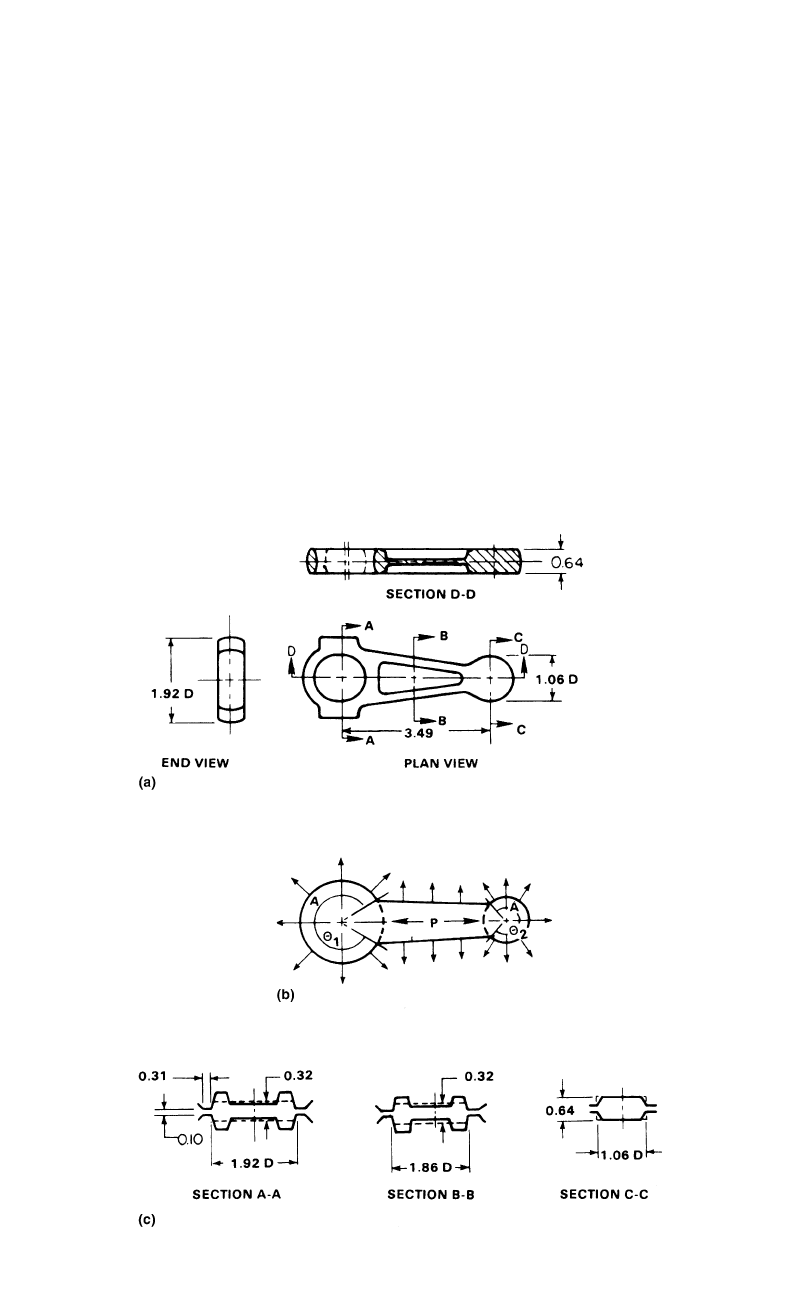
Fig. 15.7
Geometry, directions of metal flow and representative cross sections of a connecting rod: (a) cross-sectional views of the
connecting rod, (b) directions of metal flow (A ⳱ axisymmetric, P ⳱ plane strain), (c) representative sections and their
simplification
190 / Cold and Hot Forging: Fundamentals and Applications
method can show the trend in the calculation of
forging load while the FEM only provides the
final calculated results.
15.4 A Simplified
Method for Load Estimation
The present method, used in practical predic-
tion of forging load, works on a simplified
model of impression-die forging and uses the
slab analysis technique. It is assumed that for all
cross sections of forging, the cavity is rectan-
gular and has the flash geometry, as illustrated
in Fig. 15.3. In actual practice, where the cavity
is not rectangular, the cross section is simplified
to conform to this model. The load calculation
is simplified by dividing a complex forging in
simpler components where metal flow is either
axisymmetric or plane strain, as shown in Fig.
15.4. Then the load is estimated by adding the
loads calculated for each component. In load es-
timation, to take into account the change of flow
stress due to temperature change during the hot
forging operation, heat-transfer analysis is con-
ducted. The advantage of this approach is that
the effect of certain process parameters on the
forging load can be investigated quickly. This
enables an industrial designer to know the trend
of design variables by conducting a parametric
study when he is designing a new forging opera-
tion. For example, the effect of dimensional pa-
rameters such as flash thickness, t, and width, w,
on the total forging load can be easily obtained
(Fig. 15.3).
15.4.1 Simplification of
Forging Geometry
Any arbitrary three-dimensional forging is
transformed into a simplified forging model.
This model, including the simplified plane-strain
and axisymmetric metal flows, allows conduct-
ing slab analysis for load estimation. As shown
in Fig. 15.5(b), it is assumed that a simplified
forging model is divided into an axisymmetric
component of radius L and a plane-strain com-
ponent of length L
s
. The plan area, A
s
, of a sim-
plified model is equal to the plan area of the
actual forging and is represented by A
s
⳱ pL
2
Ⳮ 2L
s
L. Also, the perimeter, P
s
, of a simplified
model is equal to the perimeter of the plan area
of the actual forging and is expressed by
P
s
⳱2pL Ⳮ 2L
s
.A
s
and P
s
of an actual forging
part can be determined from any solid modeling
software commonly used in industry. Once A
s
Table 15.3 Estimated flow stresses and forging loads
Axisymmetric portion Plane-strain portion
Component Cavity Flash Cavity Flash
Temperature, F(C) 2,055 (1124) 2,013 (1101) 2,063 (1128) 2,015 (1102)
Flow stress, psi (MPa) 15,298 (105) 18,467 (127) 14,958 (103) 18,409 (127)
Forging load, tons 34 18 241 47
52 (cavity Ⳮ flash) 288 (cavity Ⳮ flash)
Total forging load, tons 340 (axisymmetric Ⳮ plane strain)
Table 15.2 Inputs for the load estimation of
connecting rod
Material data
Flow stress SS 304
Specific heat, Btu/lb•F (J/kg•K) 0.116 (486)
Density, lb/in.
3
(g/cm
3
) 0.285 (7.8)
Equipment data
Press type Mechanical
Press speed, rpm 50
Press stroke, in. (cm) 14 (36)
Geometry data
Initial billet height, in. (mm) 1.12 (28)
Flash thickness, in. (mm) 0.1 (2.5)
Flash width, in. (mm) 0.3 (7.6)
Perimeter, in. (cm) 13.67 (34.7)
Projected area, in. (cm) 6.55 (16.6)
Cavity height, in. (mm) 0.56 (14.2)
Interface data
Friction factor 0.3
Heat-transfer coefficient 0.0039 Btu/in.
2
/s/F
(3.1889 W/m
2
•K)
Initial billet temperature, F(C) 2050 (1120)
Initial die temperature, F(C) 400 (205)
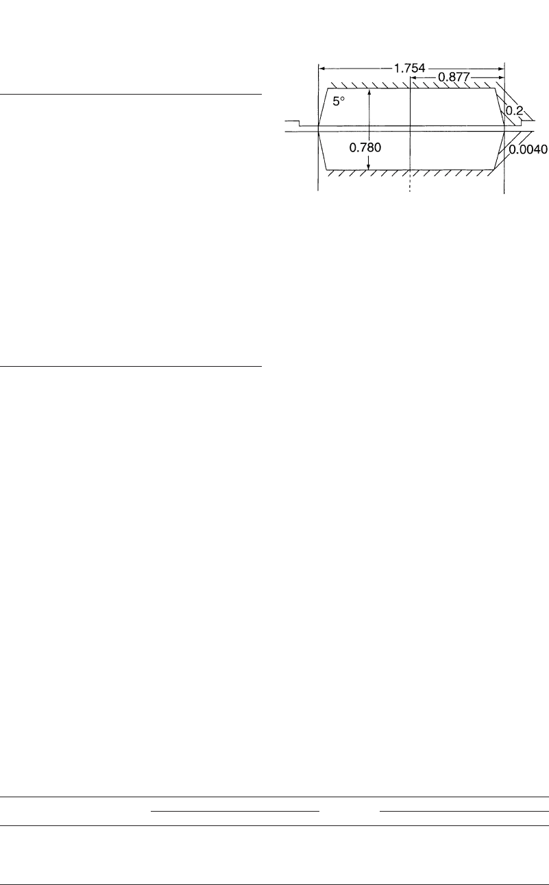
Fig. 15.8 Lead disk forging

A Simplified Method to Estimate Forging Load in Impression-Die Forging / 191
and P
s
are known, L and L
s
are found. The cross
section of the simplified model is simplified, as
shown in Fig. 15.5(d). The cavity height is de-
noted by H and the radius (or half width of the
cavity) by L, the flash thickness by t and the
flash width by w. The cavity height, H, is the
average height of the actual forging and is ob-
tained by dividing the volume of the forging
without flash by its plan area.
15.4.2 Metal Flow in the Cavity
The load estimation is made for the final stage
of forging operation when the die is totally filled
and the load has its maximum value. In the im-
pression-die forging, an approximate metal flow
in the die cavity at the final forging stage de-
pends on the cavity height, the cavity width, and
flash thickness.
For a large flash thickness (cavity width to
cavity thickness ratio is greater than 2), material
is assumed to flow into the flash by shearing
along a fictitious disk having the same thickness
as the flash, as shown in Fig. 15.6(a).
If the die cavity height is small in relation to
its width, the material forms a dead metal zone
at the die corners, and the material slides along
AB and flows by internal shearing along the line
BC (Fig. 15.6b). At the surface BC, the friction
factor is then 1.
For a high cavity height to cavity width ratio,
the material forms a shear surface ABC, and a
sticking friction condition is assumed at this sur-
face (friction factor, m ⳱ 1) (Fig. 15.6c). The
shearing height, h
s
, and shearing angle, ␣, is de-
termined analytically. In the present method, the
type of metal flow in the die cavity is determined
based on the principle that material flows in a
manner that consumes a minimum amount of
plastic deformation energy. Table 15.1 shows the
equations derived for each type of metal flow to
calculate the load components.
15.5 Example of Load Estimation
The introduced load estimation method has
been programmed at the Engineering Research
Center for Net Shape Manufacturing. ForgePAL
is a computer program running on the program-
mable controller and calculates the forging load
of impression-die forging. Examples of
ForgePAL were shown in this section. A copy
of ForgePAL is included in Appendix 15.A,
given on the CD attached to this book.
15.5.1 Connecting Rod Forging
As discussed earlier in Appendix A of Chap-
ter 14, Nagpal and Altan [Nagpal et al., 1975]
calculated the forging load for the stainless steel
connecting rod. The same dimensions are used
in ForgePAL to estimate the forging load (Fig.
15.7). The other necessary forging conditions
are approximated here. Based on the geometry
transformation rule, the connecting-rod part was
simplified. The perimeter, plan area, and volume
of the forging were found by using a solid mod-
eling software, and the cavity height was cal-
culated (Table 15.2). However, this average
height may not be realistic for certain forging
parts. If the profile of the die is too complex
(changing greatly in height), simply dividing
volume by plan area may yield poor results. In
such cases, the user should experiment with re-
sults and try to guess a more realistic height in-
put.
Simplification of Forging Geometry. With
the perimeter and projected area of the connect-
ing rod, the half cavity length, L, and the depth
of the plane-strain component, L
s
, were found
as follows:
L ⳱ 0.5482 in. and L ⳱ 5.113 in.
s
Estimation of Flow Stress. Using the mate-
rial input data, such as density, specific heat, and
heat-transfer coefficient of SS 304, ForgePAL
first calculated the average forging temperature
required for estimating the flow stress value at
the end of the forging stroke. The results of the
calculations are summarized in Table 15.3.
Table 15.4 Comparison of forging load
ForgePAL
Nagpal
and Altan
Experimental
results
Total forging load, tons 340 312 320
Table 15.5 Geometry input and estimated forging load for a lead disk forging
Flash thickness, t, in. (mm) 0.004 (0.10) . . . ForgePAL Measured
Flash width, w, in. (mm) 0.2 (5.1) Flash load, ton 7 N/A
Cavity height, h
f
, in. (mm) 0.780 (19.8) Cavity load, ton 35 N/A
Half die length, L, in. (mm) 0.877 (22.3) Total load, ton 42 41

192 / Cold and Hot Forging: Fundamentals and Applications
Estimation of Forging Load. The load cal-
culation method for a complex part is based on
the addition of the loads calculated for each
component. The forging load of each component
consists of the cavity load and the flash load.
Finally, the total forging load for the connecting
rod is equal to the combination of the load for
the axisymmetric and plane-strain portions. As
is shown in Table 15.4, a total forging load of
340 tons is predicted and its results are com-
pared with experimental results.
15.5.2 Forging of a Lead Disk with Flash
[Schey et al.] measured separately the flash
and the cavity loads in lead disk forging, as
shown in Fig. 15.8. In this reference, the flow
stress values in the cavity, and in the flash,¯r ,
c
are given as:¯r ,
f
¯r ⳱ 2,300 psi and ¯r ⳱ 5,300 psi
cf
The part is symmetric and round about the
center axis with flash at the periphery. Thus, the
axisymmetric model is selected for load calcu-
lation in ForgePAL. The necessary axisymme-
tric geometry inputs obtained from Fig. 15.8 and
estimated forging loads are summarized in Table
15.5.
REFERENCES
[Altan et al., 1983]: Altan, T., Oh, S.I., Gegel,
H., Metal Forming Fundamentals and Appli-
cations, American Society for Metals, 1983.
[Mohammed et al., 1999]: Asaduzzaman, M.,
Demir, A., Vazquez, V., Altan, T., “Develop-
ment of Computer Program for Estimation of
Forging Load and Die Pressures in Hot Forg-
ing,” Report No. F/ERC/NSM-99-R-18, En-
gineering Research Center for Net Shape
Manufacturing, The Ohio State University,
1999.
[Nagpal et al., 1975]: Nagpal, V., and Altan, T.,
“Estimation of Forging Load in Closed-Die
Forging,” Battelle Columbus Laboratories,
1975.
[Schey et al.]: Schey, J.A., et al., “Metal Flow in
Closed-Die Press Forming of Steel,” Research
Report to American Iron and Steel Institute, IIT
Research Institute, Chicago, Illinois.
SELECTED REFERENCES
●
[Douglas et al., 1989]: Douglas, J.R., and
Altan, T., “Flow Stress Determination for
Metals at Forging Rates and Temperatures,”
Trans. ASME, J. Eng. Industry, Feb. 1975, p
66, 1989.
●
[Lange, 1985]: Lange, K., Handbook of
Metal Forming, McGraw-Hill Book Com-
pany, 1985.
●
[Schultes et al., 1981]: Schultes, T., Sev-
enler, K., Altan, T., “Prediction of Forging
Load and Stresses Using a Programmable
Calculator,” Topical Report No. 4, Battelle
Columbus Laboratories, 1981.
●
[Subramanian et al., 1980]: Subramanian,
T.L., and Altan, T., “Practical Method for
Estimating Forging Loads with the Use of
a Programmable Calculator,” Journal of
Applied Metal Working, No. 2, Jan. 1980,
p 60.