Еврокод 3. Проектирование стальных конструкций. Часть 4-1. Бункеры
Подождите немного. Документ загружается.

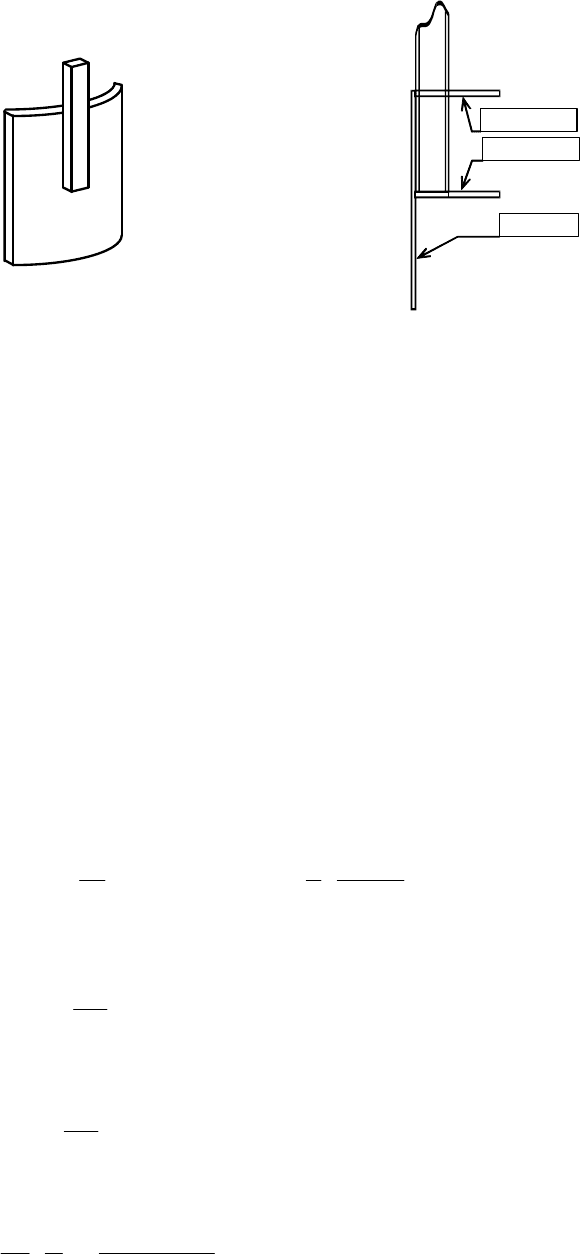
Rib
Shell wall
Lower ring
Upper ring
Loc
al rib without rings attached to
cylindrical wall
Local rib with stiffening rings to resist
radial displacements
Figure 5.8: Typical details of loading rib attachments
5.4.7 Anchorage at the base of a silo
(1) The design of the anchorage should take account of the circumferential non-uniformity of the
actual actions on the shell wall. Particular attention should be paid to the local high anchorage
requirements needed to resist wind action.
NOTE: Anchorage forces are usually underestimated if the silo is treated as a cantilever beam under
global bending.
(2) The separation between anchorages should not exceed the value derived from consideration of
the base ring design, given in 8.5.3.
(3) Unless a more thorough assessment is made using numerical analysis, the anchorage design
should have a resistance adequate to sustain the local value of the uplifting force n
x,Ed
per unit
circumference:
2
2
1
, , 1
2
2 3
3
1
2 4
M
x Ed n Edw m
m
L a
n p C m C
r a a
=
= + −
+
∑
... (5.85)
2
1
1 10,4
r
a
mL
= +
... (5.86)
2
2
1 7,8
r
a
mL
= +
... (5.87)
3
3
3
4 2 2
1
3
( 1)
z
r t r
a
I L m m
=
−
... (5.88)
where:
p
n,Edw
is the design value of the stagnation point pressure under wind;
L is
the total height of the cylindrical shell wall;
t is the mean thickness of the cylindrical shell wall;
EN 1993-4-1:2007 (Е)
56

I
z
is the second moment of area of the ring at the upper edge of the cylinder about its
vertical axis (circumferential bending);
C
m
are the harmonic coefficients of the wind pressure distribution around the
circumference
M is the highest harmonic in the wind pressure distribution.
NOTE: The values for the harmonic coefficients of wind pressure C
m
relevant to specific conditions
may be chosen by the National Annex. The following gives a simple recommendation for Class 1 and
2 silos: M = 4, C
1
= +0,25, C
2
= +1,0, C
3
= +0,45 and C
4
= −0.15. For Class 3 silos, the more
precise distributions with M = 4 for isolated silos and M = 10 for grouped silos given in Annex C are
recommended.
5.5 Detailing for openings in cylindrical walls
5.5.1 General
(1) Openings in the wall of the silo should be reinforced by vertical and horizontal stiffeners
adjacent to the opening. If any material of the shell wall lies between the opening and the stiffener, it
should be ignored in the calculation.
5.5.2 Rectangular openings
(1) The vertical reinforcement around a rectangular opening (see figure 5.9) should be dimensioned
so that the cross-sectional area of the stiffeners is not less than the cross-sectional area of the wall that
has been lost, but not more than twice this value.
(2) The horizontal reinforcement should be dimensioned so that the cross-sectional area of the
stiffeners is not less than the cross-sectional area of the wall that has been lost.
(3) The flexural stiffness of the stiffeners orthogonal to the direction of the membrane stress
resultant should be chosen so that the relative displacement
δ
of the shell wall in the direction of the
stress resultant on the centreline of the opening and resulting from the presence of the opening is not
greater than
δ
max
, determined as:
max 1d
t
k d
r
δ
= ⋅
... (5.89)
where d is the width of the opening normal to the direction of the stress resultant.
NOTE: The National Annex may choose the value of k
d1
. The value k
d1
= 0,02 is recommended.
(4) The vertical reinforcing stiffeners should extend not less than 2 rt above and below the
opening.
(5) The shell should be designed to resist local buckling of the wall adjacent to the termination of
the stiffeners using the provisions of 5.4.5 and 5.4.6 for local loads.
EN 1993-4-1:2007 (Е)
57
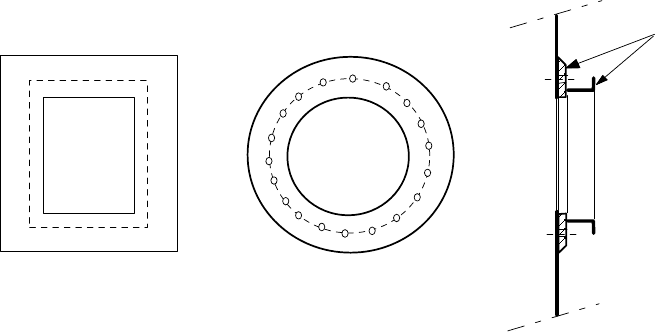
reinforcing structure
(welded or bolted on silo wall)
rectangular opening circular opening
Figure 5.9: Typical stiffening arrangements for openings in silo walls
5.6 Serviceability limit states
5.6.1 Basis
(1) The serviceability limit states for steel silo cylindrical plated walls should be taken as:
− deformations or deflections that adversely affect the effective use of the structure;
− deformations, deflections, vibration or oscillation that causes damage to both structural and
non-structural elements.
(2) Deformations, deflections and vibrations should be limited to meet the above criteria.
(3) Specific limiting values, appropriate to the intended use, should be agreed between the
designer, the client and the relevant authority, taking account of the intended use and the nature of the
solids to be stored.
5.6.2 Deflections
(1) The limiting value for global horizontal deflection should be taken as:
w
max
= k
d2
H ... (5.90)
w
here H is the height of the structure measured from the foundation to the roof.
NOTE: The National Annex may choose the value of k
d2
. The value k
d2
= 0,02 is recommended.
(2) The limiting value for local radial deflection (departure of cross-section from circular) under
wind should be taken as the lesser of:
w
r,max
= k
d3
r ... (5.91)
w
r,max
= k
d4
t ... (5.92)
where t is the local thickness of the thinnest part of the shell wall.
NOTE: The National Annex may choose the values of k
d3
and k
d4
. The values k
d3
= 0,05 and
k
d4
= 20 are recommended.
EN 1993-4-1:2007 (Е)
58
6 Design of conical hoppers
6.1 Basis
6.1.1 General
(1) Conical hoppers should be so proportioned that the basic design requirements for ultimate limit
states given in section 2 are satisfied.
(2) The safety assessment of the conical shell should be conducted using the provisions of EN
1993-1-6.
6.1.2 Hopper wall design
(1) The conical wall of the hopper should be checked for:
− resistance to rupture under internal pressure and wall friction;
− resistance to local yielding in bending at the transition;
− resistance to fatigue failure;
− resistance of joints (connections);
− resistance to buckling under transverse loads from feeders and attachments;
− local effects.
(2) The shell wall should satisfy the provisions of EN 1993-1-6, except where 6.3 to 6.5 provide
conditions that are deemed to satisfy the provisions of that standard.
(3) The rules given in 6.3 to 6.5 may be used for hoppers with hopper half angles in the range 0° <
β
< 70°.
(4) For hoppers in Consequence Class 1, the cyclic plasticity and fatigue limit states may be
ignored, provided that both the following two conditions are met:
a) The design for the rupture at the transition junction should be carried out using an
enhanced partial factor of
γ
M0
=
γ
M0g
.
b) No local meridional stiffeners or supports are attached to the hopper wall near the
transition junction.
NOTE: The National Annex may choose the value of
γ
M0g
. The value
γ
M0g
= 1,4 is recommended.
6.2 Distinctions between hopper shell forms
(1) A hopper wall constructed from flat rolled steel sheet should be termed 'isotropic'.
(2) A hopper wall with stiffeners attached to the outside should be termed 'externally stiffened'
(3) A hopper with more than one discharge orifice should be termed 'multiple outlet'
(4) A hopper which forms part of a silo supported on discrete column or bracket supports should be
termed 'discretely supported', even though the discrete supports are not directly beneath the hopper.
EN 1993-4-1:2007 (Е)
59
6.3 Resistance of conical hoppers
6.3.1 General
(1) The conical hopper should satisfy the provisions of EN 1993-1-6. Alternatively, these may be
deemed to be satisfied using the assessments of the design resistance given in 6.3.
(2) Special attention should be paid to the possibility that different parts of the hopper can be
critically loaded under the pressure patterns of either filling or discharge actions.
(3) The stress resultants arising in the body of the hopper may generally be found using the
membrane theory of shells.
NOTE: Additional information relating to the pressure patterns which may occur and the membrane
theory stress resultants in the hopper body is given in Annex B.
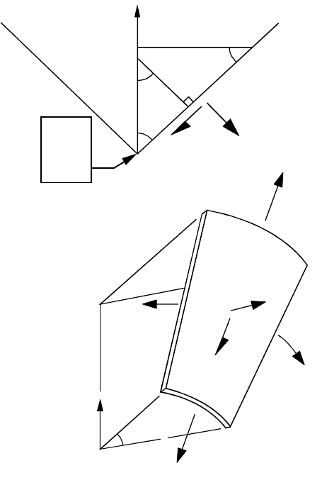
Figure 6.1: Hopper shell segment
6.3.2 Isotropic unstiffened welded or bolted hoppers
6.3.2.1 General
(1) A conical hopper should be treated as a shell structure, recognising the coupling of meridional
and circumferential actions in supporting loads.
n
θ
p
t
θ
β
φ
φ
p
n
p
t
origin
an
apex
n
θ
p
n
z
n
φ
n
φ
z
EN 1993-4-1:2007 (Е)
60
6.3.2.2 Plastic mechanism or rupture in the hopper body
(1) The design against rupture should recognise that the hopper can be subject to different patterns
and changing patterns of pressures on the wall. Because failure by rupture can easily propagate and is
generally not ductile, every point in the hopper should be able to resist the most severe design
condition.
(2) Welded or bolted joints running down the meridian within the conical hopper should be
proportioned at each point to sustain the worst membrane forces arising from either the filling or the
discharge pressure distribution.
(3) Welded or bolted joints running around the hopper circumference should be proportioned to
sustain the maximum total weight of solids that can be applied below that point.
NOTE: This is generally defined by the filling pressure distribution: see EN 1991-4.
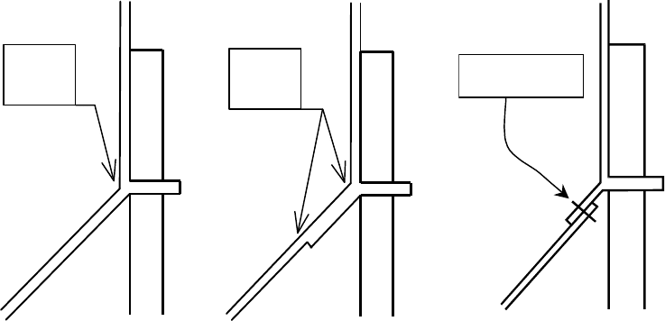
6.3.2.3 Rupture at the transition junction
(1) The circumferential joint between the hopper and the transition junction, see Figure 6.2, should
be designed to carry the maximum total meridional load that the hopper can be required to support,
allowing for possible unavoidable non-uniformities.
Critical
joint
Critical
joints
Critical joint
a) in welded construction b) in bolted construction
Figure 6.2: Hopper transition joint: potential for rupture
(2) Where the only loading under consideration is gravity and flow loading from the stored solid,
the meridional force per unit circumference n
φh,Ed,s
caused by the symmetrical pressures defined in
EN 1991-4 that must be transmitted through the transition joint should be evaluated using global
equilibrium. The design value of the local meridional force per unit circumference n
φh,Ed
, allowing
for the possible non-uniformity of the loading, should then be obtained as
n
φh,Ed
= g
asym
n
φh,Ed,s
… (6.1)
where:
n
φh,Ed,s
is the design value of the meridional membrane force per unit circumference at
the top of the hopper obtained assuming the hopper loads are entirely
symmetrical;
g
asym
is the unsymmetrical stress augmentation factor.
EN 1993-4-1:2007 (Е)
61

NOTE: Expressions for n
φh,Ed,s
may be found in Annex B. The National Annex may choose the
value of g
asym
. The value g
asym
= 1,2 is recommended.
(3) For silos in Consequence Class 2, an elastic bending analysis should be made of the hopper
where other loads from discrete supports, feeders, attached members, non-uniform hopper pressures
etc. are involved. This analysis should determine the maximum local value of the meridional force
per unit circumference to be transmitted through the hopper to transition junction joint.
(4) The design resistance of the hopper at the transition joint n
φh,Rd
should be taken as:
n
φh,Rd
= k
r
t f
u
/
γ
M2
... (6.2)
where f
u
is the tensile strength.
NOTE: The National Annex may choose the value of k
r
. The value k
r
= 0,90 is recommended.
6.3.2.4 Plastic mechanism at thickness changes or at the transition
(1) The plastic mechanism resistance of the hopper should be evaluated in terms of the local value
of meridional membrane stress resultant n
φ
at the upper edge of the cone or at a change of plate
thickness.
(2) The design resistance n
φ,Rd
should be determined from:
, 0
0,91 0,27
/
0,15
2,4 sin
cos
y
Rd M
rtf
n
rt
r
φ
µ
γ
µ
β
β
+
=
+
− ⋅
... (6.3)
where:
t is the local wall thickness;
r is the radius at the top of the plastic mechanism (hopper top or change of plate
thickness);
β
is the hopper half angle, see figure 6.1;
µ
is the wall friction coefficient for the hopper.
EN 1993-4-1:2007 (Е)
62

(3) At each critical point in the structure, the design stresses should satisfy the condition:
n
φ,Ed
≤ n
φ,Rd
... (6.4)
p
nh
p
nc
µ
p
nh
µ
p
nc
Fig
ure 6.3: Plastic collapse of conical hopper
6.3.2.5 Local flexure at the transition
(1) To avoid cyclic plasticity and fatigue failures, the hopper should be designed to resist the severe
local flexure at the top of the hopper that arises from both compatibility and equilibrium effects.
(2) This requirement may be ignored for silos of Consequence Class 1.
(3) In the absence of a finite element analysis of the structure, the value of the local bending stress
at the top of the hopper should be assessed using the following procedure.
(4) The effective radial force F
e,Ed
and moment M
e,Ed
acting on the transition ring should be
determined from:
F
e,Ed
= n
φh,Ed
sin
β
− F
h
− F
c
... (6.5)
M
e,Ed
= F
c
x
c
− F
h
x
h
... (6.6)
with:
F
c
= 2 x
c
p
nc
... (6.7)
F
h
= 2 x
h
(0,85 − 0,15
µ
cot
β
) p
nh
... (6.8)
x
c
= 0,39 rt
c
... (6.9)
x
h
= 0,39
cos
h
rt
β
... (6.10)
where (see figure 8.4):
EN 1993-4-1:2007 (Е)
63
t
h
is the hopper local wall thickness;
t
c
is the local wall thickness of the cylinder at the transition junction;
r is the radius of the transition junction (top of the hopper);
β
is the hopper apex half angle;
µ
is the wall friction coefficient for the hopper;
n
φh,Ed
is the design value of the meridional membrane stress resultant at the top of the
hopper;
p
nh
is the local value of normal pressure on the hopper just below the transition;
p
nc
is the local value of normal pressure on the cylinder just above the transition.
(5) The local bending stress
σ
bφh,Ed
at the top of the hopper should be determined from:
σ
bφh,Ed
=
2 1 , 3 2 , ,
2
6 6
{( 2 ) ( ) }
e Ed e Ed e Ed h
h
a a M a a F F x
t
η ρ η
− − − −
∆
... (6.11)
with:
2
1 3 2
2
a a a
∆ = −
... (6.12)
ρ
= 0,78 r ... (6.13)
η
= t
h
cosβ ... (6.14)
3/ 2
3/ 2 3/ 2
1
cos
ep
h
s c
A
t
a t t
ρ
β
= + + + ... (6.15)
2 2 2
2
s c h
a t t t
= − +
... (6.16)
5/ 2 5/ 2 5/ 2
3
cos
s c h
a t t t
β
= + + ... (6.17)
where:
t
h
is the hopper local wall thickness;
t
c
is the local wall thickness of the cylinder at the transition junction;
t
s
is the local wall thickness of the skirt below the transition junction;
A
ep
is the cross-sectional area of the ring at the transition junction (without any
effective contributions from the adjacent shell segments);
r is the radius of the transition junction (top of the hopper).
6.3.2.6 Hoppers that are part of a silo resting on discrete supports
(1) If the silo is supported on discrete supports or columns, the relative stiffness of the transition
ring
girder, cylinder wall and hopper should be taken into account when assessing the non-uniformity
of the meridional membrane stresses in the hopper.
(2) This requirement may be ignored for silos of Consequence Class 1.
EN 1993-4-1:2007 (Е)
64

(3) The hopper should be designed to sustain the highest local value of meridional tension at the
hopper top (adjacent to a support) according to 6.3.2.3 and 6.3.2.4.
6.3.2.7 Buckling in hoppers
(1) This criterion may be ignored for silos of Consequence Class 1.
(2) The hopper should be assessed for its resistance to buckling failure as a consequence of
horizontal actions from feeders or attached structures, or as a result of unsymmetrical vertical actions.
(3) The design buckling resistance n
φh,Rd
at the top of the hopper should be determined from:
2
, 1
0,6 cos /
h
h Rd xh M
t
n E
r
φ
α β γ
=
... (6.18)
where:
α
xh
is the elastic buckling imperfection sensitivity factor;
t
h
is the hopper local wall thickness;
r is the radius of the transition junction (top of the hopper).
and
γ
M1
is given in 2.9.2, but n
φ,Rd
should not be taken as greater than n
φ,Rd
= t
h
f
y
/
γ
M1
.
NOTE: The National Annex may choose the value of
α
xh
. The value α
xh
= 0,10 is recommended.
(4) The meridional force at the top of the hopper should satisfy the condition:
n
φh,Ed
≤ n
φh,Rd
... (6.19)
6.4 Considerations for special hopper structures
6.4.1 Supporting structures
(1) The effect of discrete supports beneath the silo should be treated as set out in 5.4. The
support
ing structures themselves should be designed to EN 1993-1-1, with the boundary between the
silo and supporting structure as defined in 1.1 (4).
6.4.2 Column supported hopper
(1) If the hopper body itself is supported on discrete supports or columns that do not reach the
hopper top edge, the hopper structure should be analysed using the bending theory of shells, see EN
1993-1-6.
(2) Adequate provision should be made to distribute the support forces into the hopper.
(3) The joints in the hopper should be designed for the highest local value of stress resultants to be
transmitted through them.
(4) The hopper should be assessed for resistance to buckling failure in zones where compressive
membrane stresses develop, see EN 1993-1-6.
EN 1993-4-1:2007 (Е)
65