Еврокод 3. Проектирование стальных конструкций. Часть 4-1. Бункеры
Подождите немного. Документ загружается.

µ
p
n
h
h
β
β
r
p
p
n
n
h
h
p
p
n
n
c
c
l
eh
l
l
ec
r
r
-
-
l
l
eh
s
s
i
i
n
n
β
β
n
n
φh
d
d
e
e
t
t
e
e
r
r
m
m
i
i
n
n
e
e
d
d
h
h
e
e
r
r
e
e
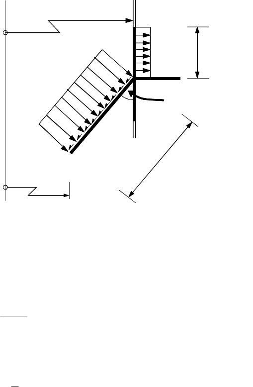
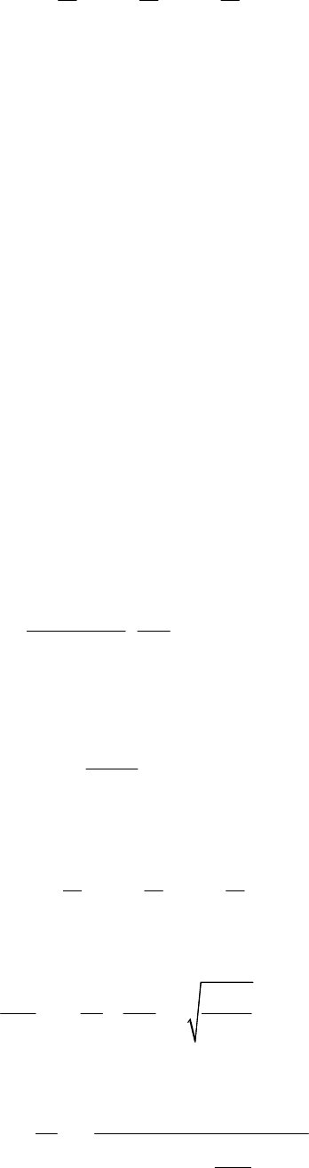
Figure 8.5: Local pressures and membrane stress resultant loadings on the
transition ring
(10) The maximum design compressive stress
σ
uθ,Ed
for the uniformly supported junction should be
determined from:
,
,
Ed
u Ed
et
N
A
θ
θ
σ
η
= ... (8.16)
with:
1 0,3
b
r
η
= + ... (8.17)
where:
N
θ,Ed
is the effective circumferential compressive force, see (9);
A
et
is the total effective area of the ring, see (7);
r
is the radius of the silo cylinder wall;
b is the width of the annular plate.
8.2.3 Transition junction ring girder
(1) For silos in Consequence Class 3, a numerical analysis of the structure should be carried out,
that models all plate elements as shell segments, and does not assume prismatic beam action in any
curved element. The analysis should take account of the finite width of the discrete supports.
(2) For silos in other Consequence Classes, the bending moments and torques within the ring girder
should be calculated, accounting for the eccentricities of loading and support from the ring girder
centroid.
(3) The total circumferential compressive thrust developed in the girder should be assumed
invariant around the circumference and determined from:
N
θ,Ed
= n
φh,Ed
r
c
sin
β
− p
nc
r
c
l
ll
l
ec
− p
nh
(cos
β
−
µ
sin
β
) r
c
l
ll
l
eh
... (8.18)
where (see figure 8.5):
EN 1993-4-1:2007 (Е)
76

r
c
is the radius of the silo cylinder wall;
β
is the half angle of the hopper (at the top);
l
ec
is the effective length of the cylinder segment above the transition (see 8.2.2 (4));
l
eh
is the effective length of the hopper segment (see 8.2.2 (4));
n
φh,Ed
is the design value of the meridional tension per unit circumference at the top of
the hopper;
p
nc
is the mean local pressure on the effective length of the cylinder segment;
p
nh
is the mean pressure on the effective length of the hopper segment;
µ
is the hopper wall friction coefficient.
(4) The variation with circumferential coordinate θ of the design bending moment M
r,Ed
about the
horizontal (radial) axis (sagging positive) and the design torsional moment T
θ,Ed
in the ring girder
should be taken as:
M
r,Ed
= n
xc,Ed
(r
g
− e
r
) [(r
g
− e
s
)
θ
o
(sin
θ
+ cot
θ
o
cos
θ
) − r
g
+ e
r
] + n
φh,Ed
e
x
(r
g
− e
r
) ...
(8.19)
T
θ,Ed
= n
xc,Ed
(r
g
− e
r
) [(r
g
− e
s
)
θ
o
(cot
θ
o
sin
θ
− cos
θ
) + r
g
(
θ
o
−
θ
)] ... (8.20)
with:
0
j
π
θ
=
... (8.21)
where (see figure 8.6):
θ
is the circumferential coordinate (in radians) measured from an origin at one
support;
θ
o
is the circumferential angle in radians subtended by the half span of the ring
girder;
j is the number of equally spaced discrete supports;
r
g
is the radius of the ring girder centroid;
e
r
is the radial eccentricity of the cylinder from the ring girder centroid (positive
where the centroid is at a larger radius);
e
s
is the radial eccentricity of the support from the ring girder centroid (positive
where the centroid is at a larger radius);
e
x
is the vertical eccentricity of the joint centre from the ring girder centroid
(positive where the centroid lies below the joint centre).
n
xc,Ed
is the design value of compressive membrane stress resultant at the base of the
cylinder:
n
φh,Ed
is the design value of tensile membrane stress resultant at the top of the hopper.
(5) The peak values of the design bending moment about the radial axis that occur over the support
M
rs,Ed
and at midspan M
rm,Ed
should be determined from:
M
rs,Ed
= n
xc,Ed
(r
g
− e
r
) [(r
g
− e
s
)
θ
o
cot
θ
o
− r
g
+ e
r
] + n
φh,Ed
e
x
(r
g
− e
r
) ... (8.22)
M
rm,Ed
= n
xc,Ed
(r
g
− e
r
) [(r
g
− e
s
)
θ
o
/ sin
θ
o
− r
g
+ e
r
] + n
φh,Ed
e
x
(r
g
− e
r
)
... (8.23)
EN 1993-4-1:2007 (Е)
77
(6) Where an open section ring girder is used, the torque should be assumed to be resisted entirely
by warping, unless a more precise analysis is used. Where warping resists the torques, the peak
design values of flange moment about a vertical axis in each flange should be taken as given by M
fs,Ed
at
the support and M
fm,Ed
at midspan, obtained as follows:
2
0
, , 0 0
( )
( )(1 cot )
3
g g r g
fs Ed xc Ed g s
r r e r
M n r e
h
θ
θ θ
−
= − − −
... (8.24)
2
0
, , 0 0
( )
( )(1 / sin )
6
g g r g
fm Ed xc Ed g s
r r e r
M n r e
h
θ
θ θ
−
= − − +
... (8.25)
where h is the vertical separation between the flanges of the ring girder.
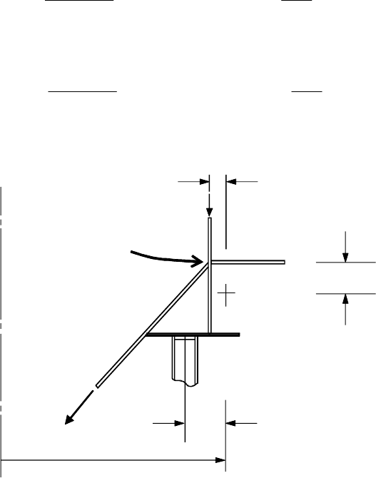
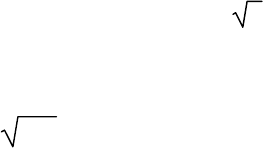
G
Ringbeam effective
section centroid, G
e
s
e
x
Axis
Cylinder/cone
transition junction
n
xc
e
r
n
φh
r
g
Figure 8.6: Eccentricities of vertical loads at a ring girder
(7) The circumferential membrane stresses
σ
θ,Ed
that develop in each flange of the ring girder
should be determined from the thrust N
θ,Ed
, radial axis moment M
r,Ed
and warping flange moments
M
f,Ed
using engineering bending and warping theory and adopting the stress resultants defined in (3)
to (6).
(8) The largest value of the circumferential membrane stress
σ
θ,Ed
(whether tensile or
compressive) that develops in either flange of the ring girder at any position around the circumference
should be determined as
σ
mθ,Ed
.
(9) The largest compressive value of the circumferential membrane stress
σ
θ,Ed
that develops in
either flange of the ring girder at any position around the circumference should be determined as
σ
cθ,Ed
.
EN 1993-4-1:2007 (Е)
78
8.3 Structural resistances
8.3.1 General
(1) The transition junction should satisfy the provisions of EN 1993-1-6, but these may be met
using the following assessments of the design resistance.
8.3.2 Resistance to plastic limit state
8.3.2.1 General
(1) The design value of the resistance should be determined using the provisions of EN 1993-1-6.
The following resistance assessments may be used instead as a simple safe approximation to those
provisions.
8.3.2.2 Resistance based on elastic evaluation
(1) The design value of the resistance should be determined at the most highly stressed point in the
junction.
(2) The design value of the resistance of the plastic limit state should be determined using:
f
p,Rd
= f
y
/
γ
M0
... (8.26)
8.3.2.3 Resistance based on plastic evaluation
(1) The design value of the resistance should be determined in terms of the attainable tensile
membrane stress resultant n
φh,Rd
in the hopper at the junction.
(2) The design value of the resistance at the plastic limit state n
φh,Rd
should be determined using:
,
0
1
(cos sin )
sin
p oc c os s oh h y
h Rd nc oc nh eh
M
A l t l t l t f
n p l p l
r
φ
β µ β
β γ
+ + +
= ⋅ + + −
... (8.27)
with:
2
2 2
c
s h
t
t t
α
=
+
... (8.28)
ψ
= 0,7 + 0,6
α
2
- 0,3
α
3
... (8.29)
- for the cylinder
l
oc
= 0,975 r t
c
- for the skirt
l
os
= 0,975
ψ
r t
s
- for the conical hopper segment
l
oh
= 0,975
ψ
cos
h
rt
β
where (see figure 8.5):
r is the radius of the silo cylinder wall;
t
c
is the thickness of the cylinder;
EN 1993-4-1:2007 (Е)
79

t
s
is the thickness of the skirt;
t
h
is the thickness of the hopper;
A
p
is the cross-sectional area of the ring;
β
is the half angle of the hopper (at the top);
l
oc
is the plastic effective length of the cylinder segment above the transition;
l
oh
is the plastic effective length of the hopper segment;
l
l
os
is the plastic effective length of the skirt segment below the transition;
n
φh,Rd
is the meridional membrane resistance per unit circumference at the top of the
hopper;
p
nc
is the mean local pressure on the effective length of the cylinder segment;
p
nh
is the mean pressure on the effective length of the hopper segment;
µ
is the hopper wall friction coefficient.
8.3.3 Resistance to in-plane buckling
(1) The design value of the resistance should be determined using the provisions of EN 1993-1-6.
The following resistance assessment may be used instead as a simple safe approximation to those
provisions.
(2) The design value of the resistance should be assessed using the point in the junction where the
highest compressive circumferential membrane stress occurs.
(3) The design value of the resistance against in-plane buckling
σ
ip,Rd
should be determined using:
,
2
1
4 1
z
ip Rd
et g M
EI
A r
σ
γ
= ⋅ ... (8.30)
where:
EI
z
is the flexural rigidity of the ring effective cross-section (see figure 8.3) about its
ver
tical axis;
A
et
is the effective cross-sectional area of the ring, given by 8.2.2;
r
g
is the radius of the centroid of the ring effective cross-section.
(4) The above resistance assessment and the associated verification against in-plane bucking of 8.4
may be omitted when the cone half angle
β
is greater than
β
lim
.
NOTE: The National Annex may choose the value of
β
lim
. The value
β
lim
= 20° is recommended.
8.3.4 Resistance to out-of-plane buckling and local shell buckling near the junction
8.3.4.1 General
(1) The design value of the resistance should be determined using the provisions of EN 1993-1-6.
The following resistance assessments may be used instead as a simple safe approximation to those
provisions.
EN 1993-4-1:2007 (Е)
80
8.3.4.2 Local shell buckling near the junction
(1) For junctions in which there is either no ring at the transition (simple cone to cylinder junction),
or the transition is ring stiffened. the design value of the resistance
σ
op,Rd
against shell buckling of the
wall adjacent to the junction should be determined using:
1,5
0,4
,
1
1
4,1(cos )
g
op Rd
M s et
Etr
t
r A
σ β
γ
= ⋅ ⋅ ⋅
... (8.31)
with:
r
s
= r for the cylindrical wall
r
s
=
cos
r
β
for the conical hopper wall
where:
r is the radius of the silo cylinder wall;
β
is the hopper apex half angle;
t is the thickness of the relevant shell segment;
A
et
is the effective cross-sectional area of the ring, given by 8.2.2;
r
g
is the radius of the centroid of the ring effective cross-section.
8.3.4.3 Annular plate transition junction
(1) For junctions in which the ring at the transition is in the form of an annular plate, the design
value of the resistance against out-of-plane buckling
σ
op,\,Rd
should be determined using:
2
,
1
1
p
op Rd
M
t
kE
b
σ
γ
= ⋅
... (8.32)
with:
c c s s
c s
k k
k
η η
η η
+
=
+
... (8.33)
k
s
= 0,385 + 0,452
b
r
... (8.34)
k
c
= 1,154 + 0,56
b
r
... (8.35)
η
s
= 0,43 + 0,1
2
20
r
b
... (8.36)
EN 1993-4-1:2007 (Е)
81
η
c
= 0,5
5/ 2 5 / 2 5/ 2
c s h
p p p
t t t
t t t
+ +
... (8.37)
where:
r is the radius of the silo cylinder wall;
t
c
is the thickness of the cylinder;
t
s
is the thickness of the skirt;
t
h
is the thickness of the hopper.
t
p
is the thickness of the annular plate ring;
b is the width of the annular plate ring;
k
c
is the plate buckling coefficient for a ring with clamped inner edge;
k
s
is the plate buckling coefficient for a ring with simply supported inner edge;
γ
M1
is the partial factor, see 2.9.2.
8.3.4.4 T section transition junction
(1) The following assessment should be used where the transition junction ring consists of an
annular plate of width b
p
with a symmetrically placed vertical stiffening flange of height b
f
at its
outer edge, forming a T section ring with the base of the T at the joint centre.
(2) The design value of the resistance against out-of-plane buckling
σ
op,Rd
of a T-section ring
beam should be determined on the basis of the maximum compressive value of the circumferential
membrane stress on the inner edge of the principal annular plate of the ring. The design value of the
resistance should be determined from:
,
1
1
s s c c
op Rd
s c M
η σ η σ
σ
η η γ
+
= ⋅
+
... (8.38)
with:
η
s
= 0,385 +
2
175
p
r
b
... (8.39)
η
c
= 0,5
5/ 2 5 / 2 5/ 2
c s h
p p p
t t t
t t t
+ +
... (8.40)
2
0
0,2 2
p t p
r t
s
r r
b GI b
EI GI
Ar r EI EI r
σ
= + +
... (8.41)
σ
p
=
( )
(
)
1,1
2
f f
1 5 1 32 16
64 1 5
p
p
p p
t
E
b
b t
b t
ρ ρ ρ
+ + −
⋅
+
... (8.42)
EN 1993-4-1:2007 (Е)
82

2
2
r z c
o
I I Ax
r
A
+ +
= ... (8.43)
1/ 3
f f
p p
b t
b t
ρ
=
... (8.44)
where:
r is the radius of the silo cylinder wall;
t
c
is the thickness of the cylinder;
t
s
is the thickness of the skirt;
t
h
is the thickness of the hopper.
t
p
is the thickness of the annular plate ring;
t
f
is the thickness of the outer vertical flange of the T section;
b
p
is the width of the annular plate ring;
b
f
is the height (flange width) of the outer vertical flange of the T section;
A
is the cross-sectional area of the T-section ring beam;
x
c
is the distance between the centroid of the T-section and its inner edge;
I
r
is the second moment of area of the T-section about its radial axis;
I
z
is the second moment of area of the T-section about its vertical axis;
I
t
is the uniform torsion constant for the T-section;
γ
M1
is the partial factor, see 2.9.2.
8.4 Limit state verifications
8.4.1 Uniformly supported transition junctions
(1) Where the silo has been analysed using a computer analysis, the procedures of EN 1993-1-6
sho
uld be used. Where the computer analysis does not include a buckling analysis, section 8.3 may be
used to provide the buckling resistances for the limit state verification in EN 1993-1-6.
(2) Where the silo is supported on a skirt extending to a uniform foundation (see 5.4.2) and the
calculations of 8.2 have been carried out, the transition junction may be deemed to be subject only to a
uniform circumferential membrane stress
σ
uθ,Ed
as determined in 8.2.2 (10). The following limit
state verifications should then be carried out.
(3) Where the plastic limit state is assessed using an elastic evaluation, the plastic limit state for the
junction should be verified using:
σ
uθ,Ed
≤ f
p,Rd
... (8.45)
where:
σ
uθ,Ed
is the design value of the stress taken from 8.2.2 (10);
f
p,Rd
is the design value of the plastic resistance taken from 8.3.2.2.
(4) Where the plastic limit state is assessed using a plastic evaluation, the plastic limit state for the
junction should be verified using:
n
φh,Ed
≤ n
φh,
Rd
... (8.46)
where:
EN 1993-4-1:2007 (Е)
83
n
φh,Ed
is the design value of the meridional membrane stress resultant at the top of the
hop
per;
n
φh,Rd
is the design value of the plastic resistance taken from 8.3.2.3.
(5) The in-plane buckling limit state for the junction should be verified using:
σ
uθ,Ed
≤
σ
ip,Rd
... (8.47)
where:
σ
uθ,Ed
is the design value of the stress taken from 8.2.2 (10);
σ
ip,Rd
is the design value of the in-plane buckling resistance taken from 8.3.3.
(6) The limit state verification against in-plane buckling may be omitted if both of the following
conditions are met:
− the cone half angle
β
is greater than
β
lim
and there is a cylinder above the ring;
− where the cylinder has a height L less than L
min
= k
L
rt , the upper boundary of the cylinder is
restrained against out-of-round displacements by a ring with a flexural rigidity EI
z
about its
vertical axis (circumferential bending) greater than:
EI
z,min
= k
R
E (rt)
2
( )
t/r ... (8.48)
where:
t is the thickness of the thinnest strake in the cylinder.
NOTE 1: The National Annex may choose the values of
β
lim
, k
L
and k
R
. The values
β
lim
= 10°, k
L
= 10 and k
R
= 0,04 are recommended.
NOTE 2: The requirement that the top of the cylinder should be restrained to remain circular is only
relevant for short cylinders above the transition ring, since taller cylinders provide sufficient restraint
against this mode of buckling without being themselves restrained to remain circular.
(7) The out-of-plane buckling limit state for the junction should be verified using:
σ
uθ,Ed
≤
σ
op,Rd
... (8.49)
where:
σ
uθ,Ed
is the design value of the stress taken from 8.2.2 (10);
σ
op,Rd
is the appropriate design value of the out-of-plane buckling resistance taken from
8.3.4.
8.4.2 Transition junction ring girder
(1) Where the silo has been analysed using a computer analysis, the procedures of EN 1993-1-6
should be used. Where the computer analysis does not include a buckling analysis, section 8.3 may be
used to provide the buckling resistances for the limit state verification in EN 1993-1-6.
(2) Where the silo is discretely supported, so that the transition junction acts as a ring girder with
circumferential membrane stresses which vary across the section and around the circumference, this
variation should be taken into account in the limit state verifications. Where the calculations of 8.2
have been carried out, the following limit state verifications should be undertaken.
(3) The plastic limit state for the junction should use the evaluated stress
σ
mθ,Ed
from 8.2.3 (8) and
should be verified using:
EN 1993-4-1:2007 (Е)
84
σ
mθ,Ed
≤ f
p,Rd
... (8.50)
where:
σ
mθ,Ed
is the design value of the stress taken from 8.2.3 (8);
f
p,Rd
is the design value of the plastic resistance taken from 8.3.2.2.
(4) The in-plane buckling limit state for the junction should use the evaluated stress
σ
cθ,Ed
from
8.2.3 (9) and should be verified using:
σ
cθ,Ed
≤
σ
ip,Rd
... (8.51)
where:
σ
cθ,Ed
is the design value of the stress taken from 8.2.3 (9);
σ
ip,Rd
is the design value of the in-plane buckling resistance taken from 8.3.3.
(5) The limit state verification against in-plane buckling may be omitted if both of the following
conditions are met:
− the cone half angle
β
is greater than
β
lim
and there is a cylinder above the ring;
− where the cylinder has a height L less than L
min
= k
L
rt , the upper boundary of the cylinder is
restrained against out-of-round displacements by a ring with a flexural rigidity EI
z
about its
vertical axis (circumferential bending) greater than:
EI
z,min
= k
R
E (rt)
2
( )
t/r ... (8.52)
where:
t is the thickness of the thinnest strake in the cylinder;
L is the height of the shell wall above the ring.
NOTE 1: The National Annex may choose the values of
β
lim
, k
L
and k
R
. The values
β
lim
= 10°, k
L
= 10 and k
R
= 0,04 are recommended.
NOTE 2: The requirement that the top of the cylinder should be restrained to remain circular is only
relevant for short cylinders above the ring, since taller cylinders provide sufficient restraint against this
mode of buckling without being themselves restrained to remain circular.
(6) The out-of-plane buckling limit state for the junction should use the evaluated stress
σ
cθ,Ed
from 8.2.3 (9) and should be verified using:
σ
cθ,Ed
≤
σ
op,Rd
... (8.53)
where:
σ
cθ,Ed
is the design value of the stress taken from 8.2.3 (9);
σ
op,Rd
is the design value of the out-of-plane buckling resistance taken from 8.3.4.
8.5 Considerations concerning support arrangements for the junction
8.5.1 Skirt supported junctions
(1) Where the silo is supported on a skirt extending to a uniform foundation (see 5.4.2), the
tra
nsition junction may be deemed to carry only circumferential membrane stresses.
EN 1993-4-1:2007 (Е)
85