Fieldbus Foundation. System Engineering Guidelines
Подождите немного. Документ загружается.


Revision 3.1 - 70 - March 2010
7.0 FIELDBUS NETWORK/SEGMENT DESIGN GUIDELINES
7.1 FOUNDATION Fieldbus Network/Segment Topology
The FOUNDATION fieldbus installation shall use the tree, spur or combination topology. Other
topologies are not recommended.
Commentary:
Components of fieldbus segments can be connected together in various topologies. The
topology selected is often, though not always driven by the physical device location in order to
reduce installation costs. Hence, control narratives, plot plans and risk management
considerations are used in addition to P&IDs and instrument indexes in the design of a fieldbus
segment.
Spur connections shall be connected to current-limiting connections to the bus via device
couplers to provide short-circuit protection, and allow the ability to work on field devices without
a hot work permit. The device coupler should provide a non-incendive or intrinsically safe
connection to the field device. Exceptions to this may be considered when lightning surge
protection is required (see Section 7.3.5.3).
Commentary:
The drops and current limiting can be provided by device couplers in junction boxes or by
device couplers that can be field-mounted.
The connection from the marshalling cabinet/Host to the coupler(s) in the field for the
topologies shown in Sections 7.1.2, 7.1.3, and 7.1.4 are often provided by a multi-pair,
individually shielded cable of the same type (ITC) used for the individual network and spur
wires. However, spur wire may be of a smaller gauge (See Section 7.7.3).
Commentary:
Depending on whether or not segment bridging is supported in the Host, the desire to
implement control in the field may drive the need to connect all the devices for the affected
loop to reside on the same segment,.
7.1.1 Point-to-Point Topology
This topology consists of a network having a maximum of only two devices. The network could
be entirely in the field (e.g., a transmitter and valve, with no connection beyond the two) or it
could be a field device connected to a Host system (doing control or monitoring). This topology
is illustrated below and should not be used. It is not an economical design except as listed
below.
Revision 3.1 - 71 - March 2010
Figure 7.1. Example of Point-to-Point Topology.
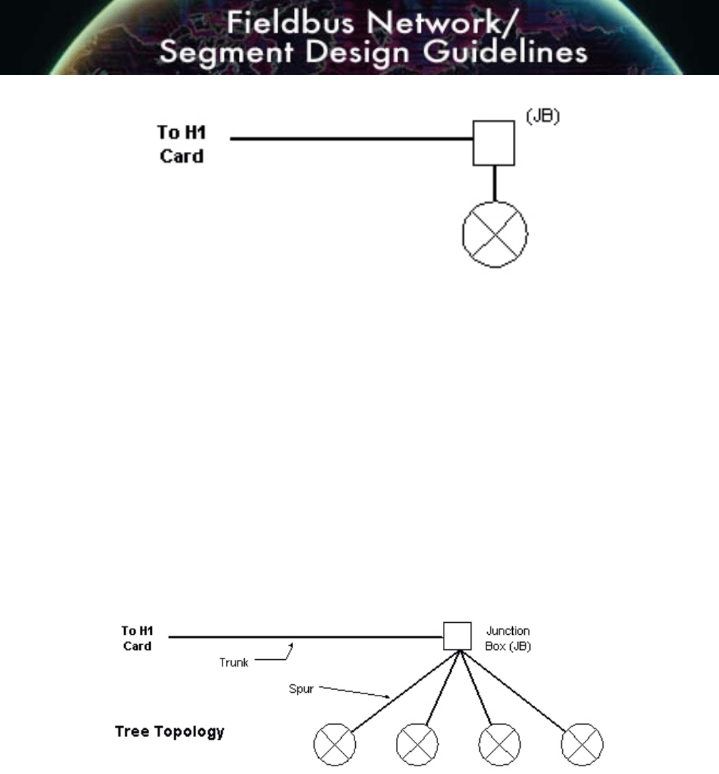
7.1.2 Tree Topology (Chicken Foot)
This topology consists of a single fieldbus segment connected to a common junction box to
form a network. This topology can be used at the end of a home run cable, and is practical if
the devices on the same segment are well separated but in the general area of the junction
box. When using this topology, the maximum spur lengths must be considered. Maximum spur
lengths are discussed in Section 7.2.4. This topology is illustrated below in Figure 7.2.
Figure 7.2. Example of Tree (Chicken’s Foot) Topology.
This is the preferred topology to be used for reuse of existing wiring, as it is most similar to the
conventional installation and will, therefore, provide the optimal use of existing infrastructure.
Tree branch topology should be used for the following situations:
• Retrofit installations
• High density of fieldbus devices in a particular area
Revision 3.1 - 72 - March 2010
This topology also allows maximum flexibility when configuring and assigning devices to
networks/segments.
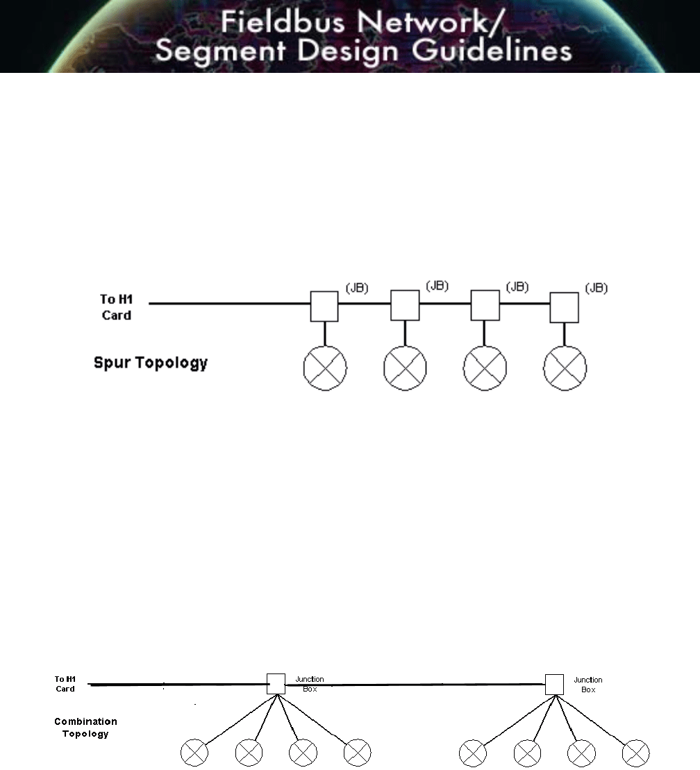
7.1.3 Spur Topology (Bus with Spurs)
This topology consists of fieldbus devices connected to a multi-drop bus segment through a
length of cable called a spur. This technology is technically acceptable, but generally not a
good economical choice when there is a high density of devices.
Figure 7.3. Example of Spur Topology.
Bus with spur topology may be used in new installations that have a low density of devices in
an area. Spurs shall be connected to current-limiting connections to the bus as this provides
short-circuit protection.
7.1.4 Combination Topology
Combinations of the above topologies must follow all the rules for maximum fieldbus
network/segment length, and include the length of spurs in the total length calculation. These
types of topologies are preferred for designs using bricks with tray cable. Spurs are permitted
to extend only from trunk lines and not from other spur lines.
Figure 7.4. Example of Combination Topology.
Commentary:
Care shall be taken to install the correct number of terminators with one terminator at the final
device coupler.
7.1.5 Daisy Chain Topology

Revision 3.1 - 73 - March 2010
This topology consists of a network/segment that is routed from device to device, and is
connected at the terminals of the fieldbus device. The topology is illustrated below in Figure
7.5. It should not be used, as it is unacceptable, for maintenance purposes.
Commentary:
The daisy chain topology is not used because devices cannot be added or removed from a
network/segment during operation without disrupting service to other devices. Similarly, failure
of one device will impact all other devices “downstream” of the failed field device, and signal
level will probably increase due to the loss of one terminator.
Figure 7.5. Example of Daisy Chain Topology.
7.2 FOUNDATION Fieldbus Wiring
7.2.1 Cable Types
For information on F
OUNDATION fieldbus wire and cable requirements, see Section 6.0 –
Segment Design Components.
7.2.2 Distance Constraints
The maximum allowed length of a non-intrinsically safe FOUNDATION fieldbus segment is
1900 m, provided that the cable meets the required specifications (See Section 6.7). This total
segment length is computed by adding the length of the main trunk line and all the spurs that
extend from it.
Total Segment Length = Trunk + All Spurs
Commentary:
From field experience, these lengths have been found to be conservative for high power
trunks. As stated in this specification, the length of a segment is limited by DC voltage drop,
power availability, and signal quality. As the end-user gains field experience, these length

Revision 3.1 - 74 - March 2010
limits may be revised shorter or longer to reflect real-world experience. See Section 7.7.4 for
further information on signal attenuation limits to segment length.
For trunks that limit power to meet non-incendive or intrinsically safe requirements, segment
length and number of devices supported will be severely limited.
7.2.3 Homerun Cable (Trunk)
Runs parallel to high power cables should be minimized, and adequate spacing and shielding
should be employed.
10% spare pairs should be provided for all multi-pair segment trunk cables, with a minimum of
one spare pair. This requirement includes spares on trunk cable runs between interface
enclosures/marshalling racks and junction boxes, and between junction boxes.
Commentary:
The decision to use multi-pair or single-pair trunk cabling depends on the number of
networks/segments installed in the field area. Typically, the trunk cable will be a multi-pair
cable if more than one network/segment is required in the area or the network/segment in the
area would be loaded to maximum. Facilities may have their own rules relative to spare
capacity requirements upon completion of a project. This is suggested as a guideline in cases
where a standard has not been established. Care should be taken to land spare trunk pairs on
terminals in order to avoid possible noise interference.
When installing FOUNDATION fieldbus in a Brownfield facility, the existing home run cables shall
be tested for suitability for reuse. This test can be done using cable testing tools (See Section
9).
Commentary:
Using existing cable has a risk of poor quality and requires field verification. Extra QA
procedures will identify bad cables (See Section 8)
At present, Relcom devices are the only known simple handheld test products available for this
service.
7.2.4 Spurs
A standard specification for maximum spur length is 120 meters. However, practical
experience, formal tests and theory all confirm that 200 meters is acceptable if the cable is
within Fieldbus Foundation specifications. IS spurs have additional distance limitations
depending on the IS design style (e.g., Entity, FISCO, Multiple Fieldbus Barriers).
Commentary:
A spur is a drop-off of the main trunk line. The trunk is considered to be the main cable run and
will contain segment terminators at each end. A spur that is less than 200 meters is negligible
as a transmission line and can accurately be modeled as an equivalent capacitor. Note:
Quarter-wavelength at H1 frequencies is around 2 kilometers. Strictly following the IEC 61158-
2 Annex B wiring guide can place unnecessary and costly restrictions on fieldbus wiring.

Revision 3.1 - 75 - March 2010
Only one (1) FOUNDATION fieldbus device shall be connected to each spur.
Commentary:
Since a short-circuit protection wiring block is being used, the segment design is limited to one
(1) device per spur. The spur length is the length of the cable from the wiring block to the
fieldbus device.
Any spur over 120 meters should require principal approval. The intent of the selected multi-
drop bus wiring method is to eliminate the need for long spur lengths and to keep spurs under
the recommended length of 30 meters or less. Longer spurs may be needed to keep the bus
out of high-risk areas. (e.g., hazardous Zone 1). A validation of device voltage at the long spur
length shall be performed as given in Table 7.4.
7.3 FOUNDATION Fieldbus Power, Grounding & Lightning Protection
7.3.1 Power
FOUNDATION fieldbus devices may be powered either from the segment (bus), or locally
powered, depending on the device design.
Commentary:
Bus-powered devices typically require 10-30 mA of current at between 9 and 32 volts. Any
network/segment designed to operate at less than 2 volts above the minimum required voltage
at any device or wiring component, normally should carry a warning about additional loads in
the network documentation. Minimum network/segment voltage should always be shown in the
network documentation.
The total current draw from all devices on the network must not exceed the rating of the
F
OUNDATION fieldbus power supply. The network/segment design must take into account:
• Total maximum device quiescent current draw
• One spur short-circuit fault (i.e., ~50 mA additional current draw)
• 15 - 25% additional current load above the two (2) previous requirements (for
inrush current and expansion, etc.)
• Current consumption of wiring components
• Test equipment (typically 12 mA per device)
The number of bus-powered (two-wire) devices on a segment is limited by the following
factors:
• Area classification requirements
• Output voltage of the FOUNDATION fieldbus power supply
• Current consumption of each device
• Current consumption of wiring components
• Location of device on the network/segment (i.e., voltage drop)
• Location of the FOUNDATION fieldbus power supply
• Resistance of each section of cable (i.e., cable characteristics)

Revision 3.1 - 76 - March 2010
• Minimum operating voltage of each device
• Additional current consumption due to one spur short-circuit fault (~40 mA)
• In-rush current caused by powering on the entire segment at once
• Segment bandwidth
Refer to Tables 7.2, 7.3, and 7.4 for calculations.
Commentary:
Current experience shows that if good quality cable is used, and if the guidelines given in this
document are followed, these calculations may not be necessary for all segments.
7.3.2 Polarity
Wiring polarity shall be maintained throughout the segment design and installation.
Commentary:
Wiring polarity is critical because although most fieldbus devices aren’t polarity-sensitive, some
instruments are. When wired with the wrong polarity, a device or device coupler may not
operate correctly.
7.3.3 Grounding
The instrument signal conductors must not be used as a ground. Instrument safety grounds
must be made through a separate conductor outside of the signal cable. FOUNDATION fieldbus
devices shall not connect either conductor of the twisted pair to ground at any point in the
network. The fieldbus signals are applied and preserved differentially throughout the network.
The grounding systems are generally the responsibility of the Electrical Engineering discipline
and shall be as specified in other documents. The following are the specific FOUNDATION
fieldbus grounding requirements.
The FOUNDATION fieldbus cable shield shall be kept isolated from the safety grounding system
except where specifically designated connections are required as shown in Figures 7-6
through 7-9, illustrating both non-incendive and IS applications.
Instrument signal conductors shall not be used as an earth/ground. If an instrument safety
earth/ground is required, it shall be made through a separate conductor. The conductor may
be in the same cable as the instrument signal conductors and shield, but shall be located
outside the shield within this cable.
Fieldbus devices should not connect either conductor of the twisted pair to earth/ground at any
point in the network.
Commentary:
The earthing/grounding of either conductor would be expected to cause some or all devices on
that bus network/segment to lose communications intermittently or completely for the period
that the conductor is earthed/grounded.

Revision 3.1 - 77 - March 2010
7.3.4 Shielding
Shielding is a very important aspect of segment design. Various options (Classes A – D) may
be used, depending on local codes, standards and practices. These classes are illustrated in
this section and larger versions of these illustrations are given in Appendix 3 for clarity.
Class A design shown in Figure 7-6 is recommended for most regions of the world. The
instrument shield is terminated at the Host (fieldbus power supply) end of the network and is
not connected to ground at any other place.
Commentary:
Some device I/O shields, such as grounded thermocouples on temperature multiplexers, may
require grounding separately from the fieldbus shield. Some regions, such as Europe, prefer
using Class B design in areas where there is equipotential grounding assured.
Class C design is an alternate recommendation shown in Figure 7-8. The instrument shield is
terminated at the Host (fieldbus power supply) end of the network in the marshalling cabinet
and is connected to ground at field devices with isolating device couplers. It is commonly used
for IS spurs on a high-power trunk.
Class D design is not recommended.
If a multiple homerun cable goes to a field junction box, do not attach the cable shield wires
from different networks together. This creates ground loops and noise onto the network.
The approaches to the grounding concepts (e.g., construction) may vary due to national
standards, but the same basic concepts (equipotential ground) are consistent worldwide.
Grounding concepts can vary depending on national standards. In Great Britain, for example,
installation with central grounding is common practice whereas in other European countries,
such as Germany, a plantwide potential matching line is usually laid. In North America, on the
other hand, the cables are often routed in pipes (conduit) that lead to the central cabinets.
Every concept has advantages and restrictions, which are set off against the plant topology
and external conditions such as the extension of the fieldbus, the grounding concept of the
plant, interference frequencies to be expected, existing Ex areas and the need to protect the
fieldbus against lightning.
Generally speaking, in all the shielding concepts, instruments are connected to a potential
matching cable with a large cross-section, which is necessary from the point of view of
explosion protection alone. This potential matching cable runs through the plant and is
grounded at one point. Depending on the building type, a separate cable does not always have
to be routed. In concrete and steel constructions, the reinforcements and additional connection
points of the constructions assume the task of potential matching. Ultimately, the guidelines
with regard to installing in hazardous areas and the applicable national regulations also have
to be observed.

Revision 3.1 - 78 - March 2010
Figure 7-6. Class A: Single-point Shielding.
Single-point shielding (Class A) requires that the shield be connect to ground at only one
location on a segment. The IEC 61158-2 recommends single-point shielding installation. The
cable shield is usually connected to the common system referencing ground (GND Reference)
through the fieldbus power supply.
The advantage of this type of installation lies in its protection against interference frequencies
up to a few megahertz. Ripple frequencies in the 50/60 Hz range and multiples thereof
(harmonic) are particularly well suppressed. These frequencies can come from power cables
routed parallel to the fieldbus cable.
Single-point shielding also offers protection against lightning. By separating the cable shield
and plant grounding, equalizing currents cannot flow over the cable shield. Thus, if lightning
strikes the plant, it cannot run through to the control system and cause damage.
Further EMC protection involves laying the fieldbus cable in a steel pipe (conduit) or armored
cable that acts as an additional Faraday shield.

Revision 3.1 - 79 - March 2010
Figure 7-7. Class B: Multi-point Shielding.
Multi-point shielding (Class B) provides the greatest degree of protection against
electromagnetic interference, similar to conduit or armored cable, in the upper frequency range
even for interferences that are above several megahertz. All the instrument and cable shields
of the bus cable are grounded locally which, in turn, has to be grounded in the safe area for
installations in hazardous areas. Multi-point grounding provides optimal protection from a
single noise source at any location.
In accordance with IEC 60079-13, Paragraph 12.2.2.3, this method can be used if the
installation is performed in such a way that provides a high degree of safety with regard to
potential matching. Under these conditions, this grounding version meets the requirements of
hazardous area installation rules.
The disadvantage of multiple grounding is seen in the event of poor equipotential ground. If
good potential matching is not possible between the grounding points of the shield, the shield
will become a current carrying conductor and induce noise into the network. The following
documents provide guidance for defining a good equipotential ground.
IEC 60079-14 (Elektrische Betriebsmittel für gasexplosionsgefährdete Bereiche-
Teil14: Elektrische anlagen für gefährdete Bereiche (ausgenommen Grubenbaue)
Multi-point grounding provides direct connection for lightning surges back to the control room
through the signal and shield wires and may require special attention.