Fieldbus Foundation. System Engineering Guidelines
Подождите немного. Документ загружается.

Revision 3.1 - 130 - March 2010
FIELD
S1
S2
FIELD
S1
FIELD
S3
FIELD
S4
FIELD
S2
FIELD
FIELD FIELD
RIE BUILDING
OUT
S1
S3
S5
IN
S2
S4
S6
OUT
S1
S3
S5
IN
S2
S4
S6
4+
5-
6s
OAS
15+
14s
13- 22-
23s
24+ 5+
6-
SHLD
PRIM CCG DELTAV RACK #5 RACK #5 17
CABINET FILE POS.
CCG DELTAV RACK #5
CCG-05-17-P01/P02
IO TYPE:
CS TAG:
FieldbusFF CH: P02
PT10038 \ FT10001 \
TT10007 \ FT10000 \
PT10037 \ FT10002
C-CCU -FT -10002
C-CCU -TT -10002
C-CCU -FT -10001
C-CCU -FT -10000
C-CCU -PT -10037
C-CCU -PT -10038
Drawing Name:
Fieldbus Segment Name:
Rev:
FIELDBUS SEGMENT DIAGRAM
Plant:
Area:
Unit:
Project:
Domain:
Revision
Date
By
No:
TAG: CCU -FT -10000
TAG: CCU -FT -10002
TAG: CCU -TT -10002
TAG: CCU -FT -10001
TAG: CCU -PT -10038
TAG: CCU -PT -10037
CCG-FFMP-009
TS-1
CCG DELTAV RACK #5
CCG-05-FBPS-18
CCG-05-17-P02-BK #2 CCG-05-17-P02-BK #1
CCG-05-17-P02-2 CCG-05-17-P02-1
CCG-FF-MP009A CCG-05-FBPS-18
BK
WH
BK
WH
BK
WH
BK
WH
BR
BL
PR#2PR#2
NOTES:
Sheet:
MARSHALLING CABINET SYSTEM CABINET
RIE BUILDING
RIE BUILDING
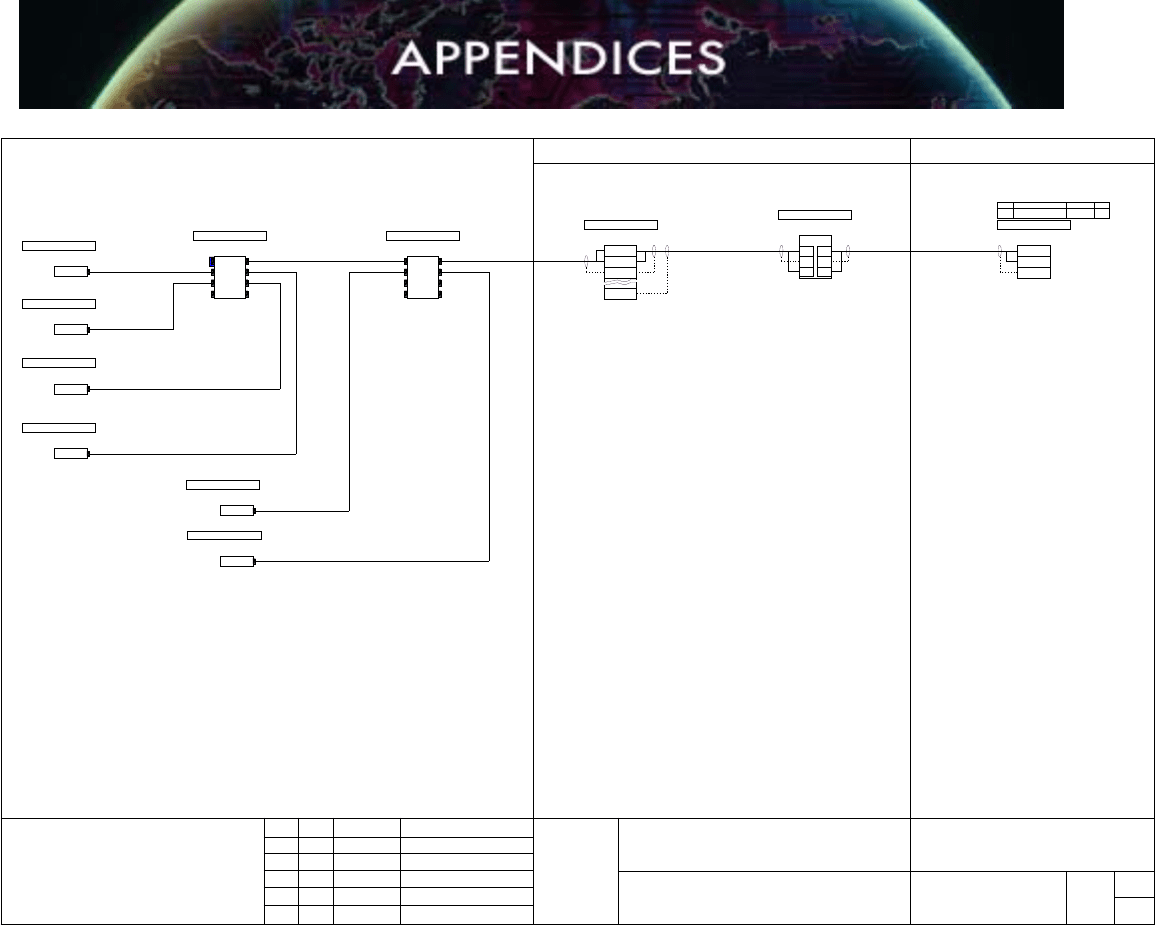
Figure A6.1. Segment Drawing Based on Connectors.
Revision 3.1 - 131 - March 2010
S1
FIELD
FIELD FIELD
RIE BUILDING
OUT
S1
S3
S5
IN
S2
S4
S6
OUT
S1
S3
S5
IN
S2
S4
S6
4+
5-
6s
OAS
15+
14s
13- 22-
23s
24+ 5+
6-
SHLD
PRIM CCG DELTAV RACK #5 RACK #5 17
CABINET FILE POS.
CCG DELTAV RACK #5
CCG-05-17-P01/P02
IO TYPE:
CS TAG:
FieldbusFF CH: P02
PT10038 \ FT10001 \
TT10007 \ FT10000 \
PT10037 \ FT10002
C-CCU -FT -10000
Drawing Name:
Loop Name:INSTRUMENT LOOP DIAGRAM
Plant:
Area:
Unit:
Project:
Domain:
Revision
Date
By
No:
TAG: CCU -FT -10000
CCG-FFMP-009
TS-1
CCG DELTAV RACK #5
CCG-05-FBPS-18
CCG-05-17-P02-BK #2 CCG-05-17-P02-BK #1
CCG-05-17-P02-2 CCG-05-17-P02-1
CCG-FF-MP009A CCG-05-FBPS-18
BK
WH
BK
WH
BK
WH
BK
WH
BR
BL
PR#2PR#2
NOTES:
Rev:Sheet:
4
5
6
OAS
BK
WH
TAG: CCU -LT -10001
CCU -LT -10001
TS - 1
CCU-LT-10001
PR #1
BK
WH
+
-
TAG: CCU -LV -10001
CCU -LV -10001
TS - 1
CCU-LV-10001
BK
WH
+
-
BK
WH
BK
WH
3
7
8
9
PR #1
PR #1
WH
BK
PR #2
PR #3
RIE BUILDING
5
6
CCG DELTAV RACK #6 RACK #6 17
CABINET FILE POS.
CCG DELTAV RACK #5
CCG-06-17-P01
IO TYPE:
CS TAG:
AO CH: 03
LV10001
CCG-02-ADCMP
RIE BUILDING
3
4
CCG DELTAV RACK #6 RACK #6 16
CABINET FILE POS.
CCG DELTAV RACK #5
CCG-06-16-P01
IO TYPE:
CS TAG:
AI CH: 02
LT10001
CCG-02-ADCMP
BK
WH
PR #2
BK
WH
PR #3
5
6
3
4
3
4
5
6
OAS
MARSHALLING CABINET SYSTEM CABINET
RIE BUILDING
RIE BUILDING
CCG-ADCMP-010
TS-1
RIE BUILDING
CCG-ADCMP-010
TS-2
RIE BUILDING
FIELD
CCG-ADCJB-001
PR #1
CCG-ADCMP-010
TS-2
RIE BUILDING
(1)
(2)
(9)
(10)
BK
BK
BK
BK
CCG-ADCMP
RIE BUILDING
OAS
CCU-ADCJB-001
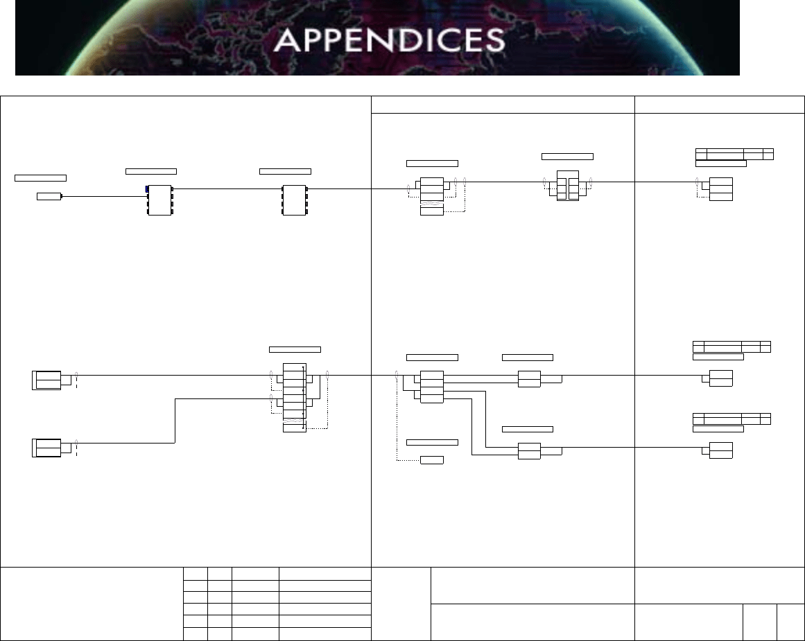
Figure A6.2. Loop Drawing for Both F
OUNDATION Fieldbus and 4-20 mA Devices.

Revision 3.1 - 132 - March 2010
T1+
T1S
T1-
1+
1S
5-
5S
5+
6-
6S
1- 6+
2+
2S
2-
3+
3S
3-
4+
4S
4-
T2+
T2S
T2- 10+
10S
10-
9+
9S
9-
8+
8S
8-
7+
7S
7-
CN13+
3S
3-
CN1
CN1
CH3+
CH3-
CH3+
CH3-
TAG: 155PIC -020 -TX
155PIC-020-TX
TS - 1
155PIC-020-TX
Pair 1
BK
BL
+
-
TAG: 155PIC -020 -TX
155PIC-020-TX
TS - 1
155PIC-020-TX
Pair 1
BK
BL
+
-
TAG: 155PIC -020 -TX
155PIC-020-TX
TS - 1
155PIC-020-TX
Pair 1
BK
BL
+
-
TAG: 155PIC -020 -TX
155PIC-020-TX
TS - 1
155PIC-020-TX
Pair 1
BK
BL
+
-
155-JF-107006
155-107-106-1
Field
FAR
FAR 1-07
IO TYPE:
CS TAG:
Fieldbus CH: 3
115PT020 \ 155TT008 \
115TT011 \ 155PV020
Plant:
Area:
Unit:
CONTRACT No. LOCATION:
DRG No.
FIELDBUS SEGMENT DIAGRAM
RevSheet
RevisionDateAppChkByRev
NOTES:
FIELD FAR
MDF SYSTEM CABINET
107-MDF-001
TPF20
155-F-107006
107-SC-0155/0156
107-DCS-005
N2-S1
SEC
PRIM 107-DCS-005 N2 1
107-DCS-005 N2 2
CABINET FILE POS.
BK
BL
Pair 1
BK
BL
Pair 1
BK
BL
Pair 1
BK
BL
Pair 1
BK
BL
Pair 1
BK
BL
Pair 1
Segment Number
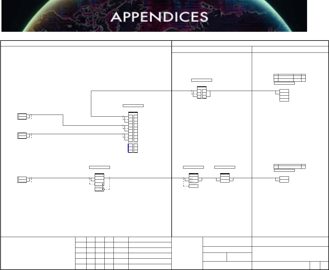
Figure A6.3. Segment Drawing Applying Device Couplers in a JB.
Revision 3.1 - 133 - March 2010
T1+
T1S
T1-
1+
1S
5-
5S
5+
6-
6S
1- 6+
2+
2S
2-
T2+
T2S
T2- 10+
10S
10-
7+
7S
7-
CN13+
3S
3-
CN1
CN1
CH3+
CH3-
CH3+
CH3-
TAG: 155LIC -002 -TX
155LIC-002-TX
TS - 1
155LIC-002-TX
Pair 1
BK
BL
+
-
TAG: 155LCV -002 -CV
155LCV-002-CV
TS - 1
155LCV-002-CV
Pair 1
BK
BL
+
-
155-JF-107008
155-107-108-1
Field
FAR
FAR 1-07
IO TYPE:
CS TAG:
Fieldbus CH: 3
115LIC002 \ 155LCV002
Plant:
Area:
Unit:
CONTRACT No. LOCATION:
DRG No.
FIELDBUS LOOP DIAGRAM
RevSheet
RevisionDateAppChkByRev
NOTES:
FIELD FAR
MDF SYSTEM CABINET
107-MDF-001
TPF21
155-F-107008
107-SC-0157/0158
107-DCS-005
N2-S3
SEC
PRIM 107-DCS-005 N2 3
107-DCS-005 N2 4
CABINET FILE POS.
BK
BL
BK
BL
Pair 1
BK
BL
Pair 1
Pair 1
Pair 1
10L+
10L-
CH8+
CH8-
FAR
FAR 1-07
IO TYPE:
CS TAG:
Analog In CH: 8
115FIC001
107-MDF-001
TPA21
107-SC-0159
107-DCS-005
N2-S5
PRIM 107-DCS-005 N2 5
CABINET FILE POS.
T1+
T1S
T1-
TAG: 155FIC -001 -TX
155FIC-001-TX
TS - 1
155FIC-001-TX
BK
Wh
+
-
155-JE-107303
TB1
Field
Pair 1
BK
Wh
Loop Number
1
2
FAR
107-MDF-001
TPA22
Pair 1
OAS
155-J-107303
155FIC-001-TX
155-J-107303
Figure A6.4. Loop Drawing Applying Both FOUNDATION Fieldbus and 4-20 mA Devices.

Revision 3.1 - 134 - March 2010
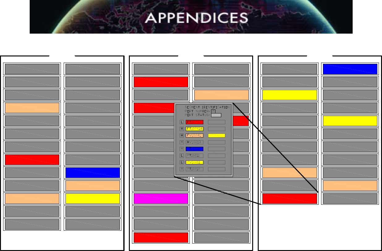
APPENDIX 7: MAINTENANCE GRAPHICS
The following screens may be used as examples of maintenance documentation and
navigation for FOUNDATION fieldbus segments. These are custom, user-built graphics that can
show the status of multiple fieldbus segments in a plant unit. Pop-up screens can show
individual segments.
The purpose of these screens is to reduce the number of mouse clicks required to navigate
through diagnostic displays from typical explorer trees while giving additional information about
device criticality and alert status (live data).
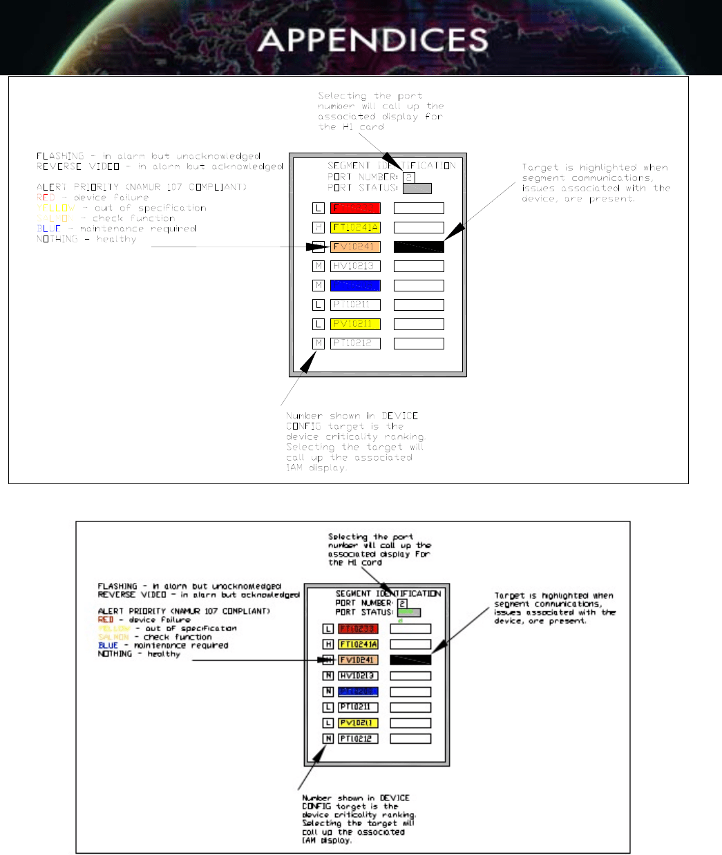
Figure A7.1 shows a typical screen for segments in a process unit. The pop-up window in that
screen shows an individual segment. Figure A7.2 shows more detail for the pop-up window.
The colors used are in compliance with the NAMUR 107 standard. All project FOUNDATION
fieldbus maintenance displays shall be NAMUR 107 compliant in the display of alert priority.
The device vendor shall provide details of device maintenance and indicate the impact of
device changes on other devices and/or Host system with regard to monitoring, historian
database, advanced diagnostics, calibrating and configuring, including a “help” guide.
Revision 3.1 - 135 - March 2010
CCGCTL01 CCGCTL02 CCGCTL03
03-01-29-02
MF2
03-01-29-01
MF2
03-01-19-01
MF2
03-01-17-02
MF2
03-01-17-01
CSS
03-01-13-02
MF2/CSS
03-01-01-01
MF2
03-01-01-02
MF2
03-01-03-01
MF2
03-01-03-02
CSS/MF2
03-01-05-01
CSS/MF1
03-01-05-02
MF2
03-01-09-01
CSS/MF2
03-01-09-02
MF2
03-01-11-01
CSS/MF2
03-01-11-02
CSS
03-01-13-01
MF2/CSS
01-01-01-01
CCS/RR2
01-01-01-02
CSS
01-01-03-01
CSS/RR2
01-01-03-02
CSS/RR2
01-01-05-01
CSS
01-01-05-02
CSS
01-01-09-01
CSS
01-01-17-02
CSS/RR2
01-01-19-01
CSS/RR2
01-01-19-02
CSS/RR2
01-01-21-01
CSS/RR2
01-01-21-02
RR2
01-01-25-01
CSS/RR2
01-01-25-02
CSS
01-01-27-01
CSS/RR2
01-01-27-02
RR2
01-01-29-01
RR2
01-01-29-02
CSS/RR2
02-01-01-01
RR1
02-01-01-02
RR1
02-01-03-01
RR1
02-01-03-02
NONE
02-01-05-01
RR1
02-01-05-02
RR1
02-01-09-01
RR1
02-01-09-02
RR1
02-01-23-02
RR1
02-01-23-01
RR1
02-01-21-02
RR1
02-01-21-01
NONE
02-01-19-02
RR1
02-01-19-01
CSS
02-01-17-02
RR1
02-01-17-01
RR1
02-01-25-01
RR1
02-01-25-02
RR1/CSS
02-01-27-01
RR1
02-01-27-02
RR1
02-01-29-01
RR1
02-01-11-01
RR1
02-01-11-02
CSS/RR1
02-01-13-01
CSS/RR1/MF1
02-01-13-02
RR1
02-01-15-01
RR1
01-01-09-02
CSS
01-01-11-01
CSS
01-01-11-02
CSS
01-01-13-01
CSS
01-01-13-02
CSS
01-01-31-01
RR2
01-01-31-02
RR2
01-01-17-01
RR2
02-01-15-02
NONE
02-01-29-02
RR1/CSS
03-01-27-02
MF2/CSS
03-01-27-01
MF2/CSS
03-01-21-02
MF2
03-01-21-01
MF2
03-01-19-02
CSS/MF2
FIELDBUS MAINTENANCE OVERVIEW
Good
Figure A7.1. FOUNDATION Fieldbus Example of Maintenance Graphic for Segments.
Revision 3.1 - 136 - March 2010
Figure A7.2. Details of FOUNDATION Fieldbus Segment Maintenance Pop-up
Graphic.
Good

Revision 3.1 - 137 - March 2010
APPENDIX 8: ACCEPTANCE TESTING PROCEDURES
A8.1 INTRODUCTION
The use of FOUNDATION fieldbus will necessitate some different or modified acceptance
testing criteria and procedures. The following is meant to be a guideline only. The use of
specific Host systems and field devices and wiring components will require modified
and/or additional procedures.
A8.2 Device Integration Testing
A complete functional test shall be conducted for each type of fieldbus device used in
the project (i.e., third-party products).
A8.2.1 Functionality Test Procedure
This test will include, but is not limited to, plug-and-play interconnectivity to the Host
system, verifying access to all Function Blocks being used in the project, actual device
operation, (e.g. stroke valves/MOVs, simulate process inputs for transmitters, etc.).
A8.2.2 Device Check
For each device to be tested, complete at least the following steps:
• Document the hardware and DD revisions of the device. Verify that
corresponding DD files are included in the Host system library. If not existing,
contact the Host manufacturer and determine the availability and add it to the
library. Some Host systems modify the files somewhat in order to ensure
compatibility with their system. Otherwise, the DDs may be obtained from the
device manufacturer or from the Fieldbus Foundation website.
• If the particular device (and revision) has been tested by the Host system vendor,
obtain the testing results (if possible) and check for any known problems and
work-arounds. Use that information to create or supplement device testing
procedures.
• Check that the database for this device is correctly populated (either by test
criteria or specific project criteria). It is assumed that the database is populated
by an upload followed by modifying the relevant ranges, alarms, units, etc. The
correct database population is checked by comparison with the relevant
documents and the physical device itself.
• Perform a download to the FOUNDATION fieldbus device and observe that no
unexplained errors occur. Host systems will report download errors. This should
include verification that all RBs and TBs can be place Out of Service (OOS) and
returned to Automatic (Auto) correctly.

Revision 3.1 - 138 - March 2010
• Observe and record the Link Master capabilities of the device. If it is Link Master
capable, ensure that the capability can be toggled off or on as the project
requires.
• Observe and record the parameter default values as received from the factory.
These values are usually available from the device manufacturer’s operation and
maintenance manuals, the defaults should be physically compared to the device
as occasionally changes are made to the devices and not updated in the
manuals in a timely manner. A determination can then be made as to which, if
any, of the default values must be made to suit the project needs.
• Perform a calibration and setup for each type of FOUNDATION fieldbus device,
using inherent device methods, or dedicated EDDL or FDT/DTM wizards
depending on the Host system and available asset management tools. All
calibration and setup procedures for each device shall be documented in detail
and approved by the end user. The test shall include a calibration and setup for
each type of device. Examples include (but are not limited to) the following:
Temperature Transmitters:
• Changing RTD/thermocouple types and downloading transmitter span
pressure transmitters
Pressure Transmitters
• Zeroing pressure and DP transmitters
• Zeroing elevation on DP level transmitters
Valve Positioners:
• Setup and calibration of a new positioner on a control valve
• Create a diagnostic alert or alarm condition and observe the annunciation in the
HMI. While that alert or alarm is still active, create another separate alert or
alarm condition and observe if that condition is also annunciated.
• For valves and other final elements, observe and record fault state actions
available within the device and simulate as many fault conditions as possible to
emulate communications loss or diagnostic alarm conditions.
Commentary:
The purpose of these requirements is to verify and document the standard default
condition of the device, the ease of access to calibration wizards and setup procedures
via the host or maintenance system as well as how the device will react to potential
conditions.
A8.3 Factory Acceptance Testing (FAT):
Develop and document procedures for the following:
A8.3.1 H1 Interface or Linking Device Operation

Revision 3.1 - 139 - March 2010
Using a test segment (with the types of wiring components and at least one field device
to be used on the project), connect the segment to every port on the H1 interface or
linking devices (including spares) at the terminal block designated for the field wiring or
system cable downstream of the fieldbus power supply.
Observe that the device(s) is recognized on the Host system live list.
If power supplies or power conditioners with switchable terminators are used, verify that
the terminator switch is in the correct position.
Verify that the DC voltage and LAS signal is within rated limits of the power supply.
Commentary:
Verification of DC voltage and LAS signal may be accomplished with hand-held test
equipment, a portable oscilloscope, or with advanced diagnostic modules (online or
offline).
A8.3.2 Redundancy Switch-over Test Procedure
Where redundant FOUNDATION fieldbus interface cards and/or power supplies are used,
the redundant operation of each component shall be tested. The test shall verify that
automatic fail over shall not cause an upset (i.e., signal bumps, loss of operator view,
mode changes, etc.). All FOUNDATION fieldbus interface cards and power supplies shall
be tested.
All failure alarms shall be tested and signed off.
A8.3 Field Device Operation
If separate Device Integration Testing is not performed prior to FAT, then use the
procedures described in Device Integration (Section A8.2) above.
A8.3.4 Data Reconciliation
For each configured parameter residing in the FOUNDATION fieldbus devices (e.g. in TB,
AI, PID or AO block), complete the following steps:
• Verify the appropriate scale and engineering units are configured as needed in
both the AI (AO) Function Block and in the Transducer Block.
• Verify that the scale and engineering units are correct and consistent for the
FOUNDATION fieldbus device and the associated faceplate, graphics and trends.
• Verify that all engineering units in the Transducer Block are consistent with the
project standards. In particular, engineering units used for diagnostic and not for
graphics may be overlooked and require extensive rework if not detected at the
device integration test.
• Simulate a process variable equal to half the scale and verify.
• The process variable appears correctly within the PV parameter field of the AI
(AO) block.