Fitzgerald A.E. Electric Machinery
Подождите немного. Документ загружается.

326 CHAPTER
6 Polyphase Induction Machines
From Eq. 6.25
Tmec h =
nphl~(R2/s)
_-- 3 x 23.92 x
4.80
Ws 125.7
= 65.4 N. m
and from Eq. 6.21
Pmech =
nphl~(R2/s)(1
-- S) ----- 3 X 23.92 X 4.80 X 0.97 = 7980 W
The curves of Fig. 6.15 were computed by repeating these calculations for a number
of assumed values of s.
b. At the maximum-torque point, from Eq. 6.35,
R2
SmaxT
R 2
V / l,eq Jr" (Xl,eq -~- X2) 2
0.144
= = 0.192
x/0.2732 + 0.6992
and thus the speed at
Tma x
is equal to (1
- SmaxT)n s -'-
(1 - 0.192) x 1200 = 970 r/min
From Eq. 6.36
Tmax = m
R2
1,eq
Ws Rl,eq
-~- V /
l,eq
-Jr-
(Xl,eq
~-
X2) 2
1 0.5 x 3 x 122.32 "]
= J = 175N.m
125.7 0.273 + ~/0.2732 + 0.6992
c. At starting, s --- 1. Therefore
,start ~-
Vl,eq
From Eq. 6.25
g/(Rl,eq -~- R2) 2 -~- (Xl,eq -~- X2) 2
122.3
= = 150A
~/0.4172 -+- 0.6992
Tstart __
nph 12R2
_-- 3 x 1502 x 0.144 __ 77.3 N. m
Ws 125.7
)ractice Problem 6.;
The rotor of the induction motor of Example 6.3 is replaced by a rotor with twice the rotor
resistance but which is otherwise identical to the original rotor. Repeat the calculations of
Example 6.2.
Solution
a. 12 = 12.4 A, Tmech = 35.0 N. m, Pmech = 4270 W
b.
Tma x -~-
175 N. m at speed = 740 r/min
c. At starting, Tstart = 128 N.m, 12,start = 136 A
6.5
Torque and Power by Use of Thevenin's Theorem
327
)ractice Problem 6.,
For the induction motor of Example 6.3, find (a) the rotor resistance required to produce peak
electromechanical torque at zero speed (i.e., SmaxT = 1.0) and (b) the corresponding torque
Tmax.
Solution
a. R2 "-0.751
f2
b. Tmax= 175N.m
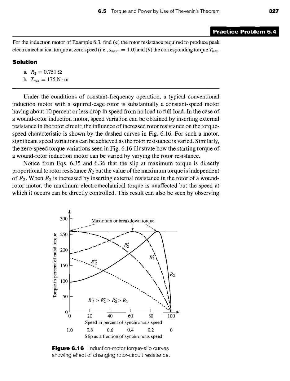
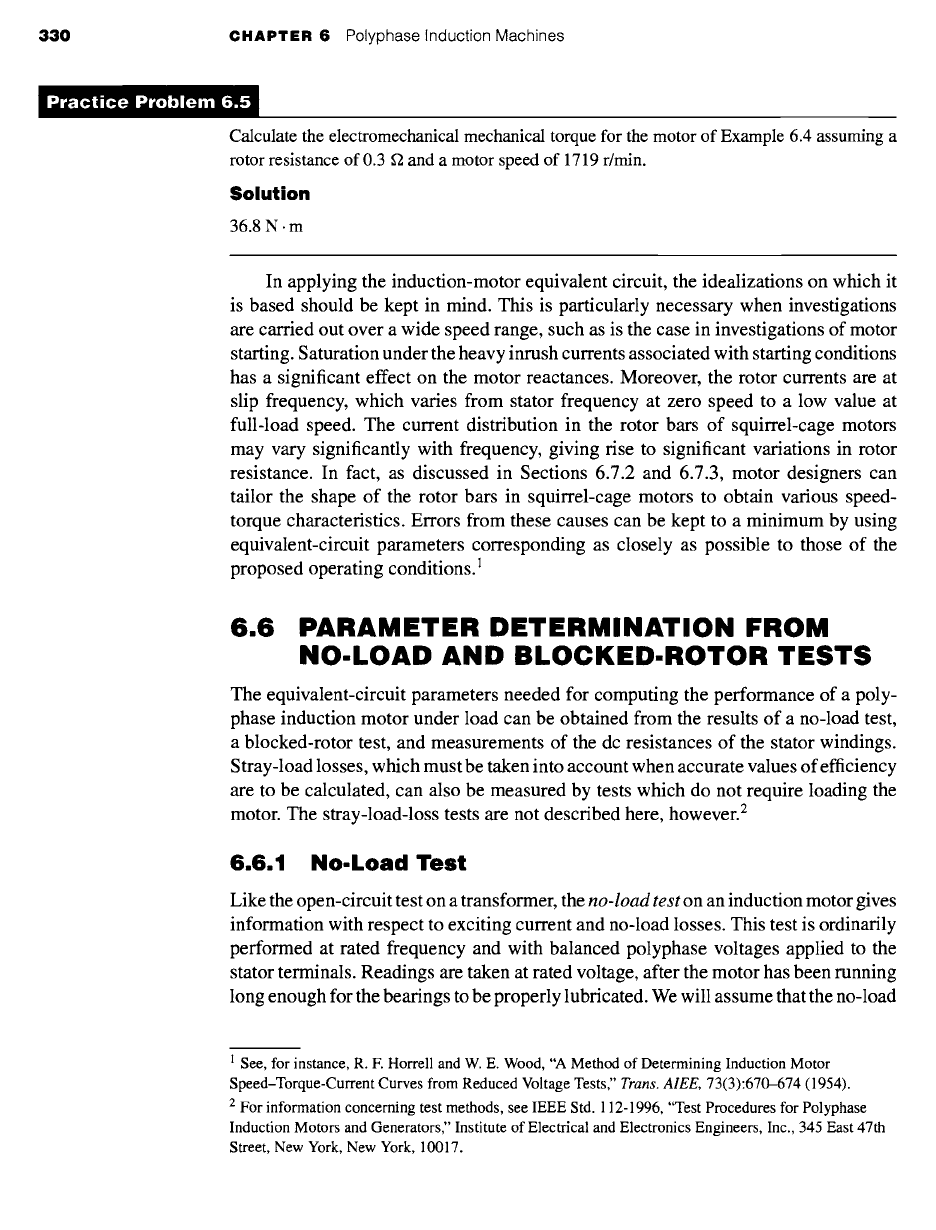
Under the conditions of constant-frequency operation, a typical conventional
induction motor with a squirrel-cage rotor is substantially a constant-speed motor
having about 10 percent or less drop in speed from no load to full load. In the case of
a wound-rotor induction motor, speed variation can be obtained by inserting external
resistance in the rotor circuit; the influence of increased rotor resistance on the torque-
speed characteristic is shown by the dashed curves in Fig. 6.16. For such a motor,
significant speed variations can be achieved as the rotor resistance is varied. Similarly,
the zero-speed torque variations seen in Fig. 6.16 illustrate how the starting torque of
a wound-rotor induction motor can be varied by varying the rotor resistance.
Notice from Eqs. 6.35 and 6.36 that the slip at maximum torque is directly
proportional to rotor resistance R2 but the value of the maximum torque is independent
of R2. When R2 is increased by inserting external resistance in the rotor of a wound-
rotor motor, the maximum electromechanical torque is unaffected but the speed at
which it occurs can be directly controlled. This result can also be seen by observing
300
250
o
.,o
~ 2oo
o
+fi 150
©
.=. lOO
~ 5o
Maximum or breakdown torque
R2
0 20 40 60 80 1 O0
Speed in percent of synchronous speed
1.0 0.8 0.6 0.4 0.2 0
Slip as a fraction of synchronous speed
Figure
6.16 Induction-motor torque-slip curves
showing effect of changing rotor-circuit resistance.
328 CHAPTER 6 Polyphase Induction Machines
that the electromechanical torque expression of Eq. 6.33 is a function of the ratio
R2/s.
Thus, the torque is unchanged as long as the ratio
R2/s
remains constant.
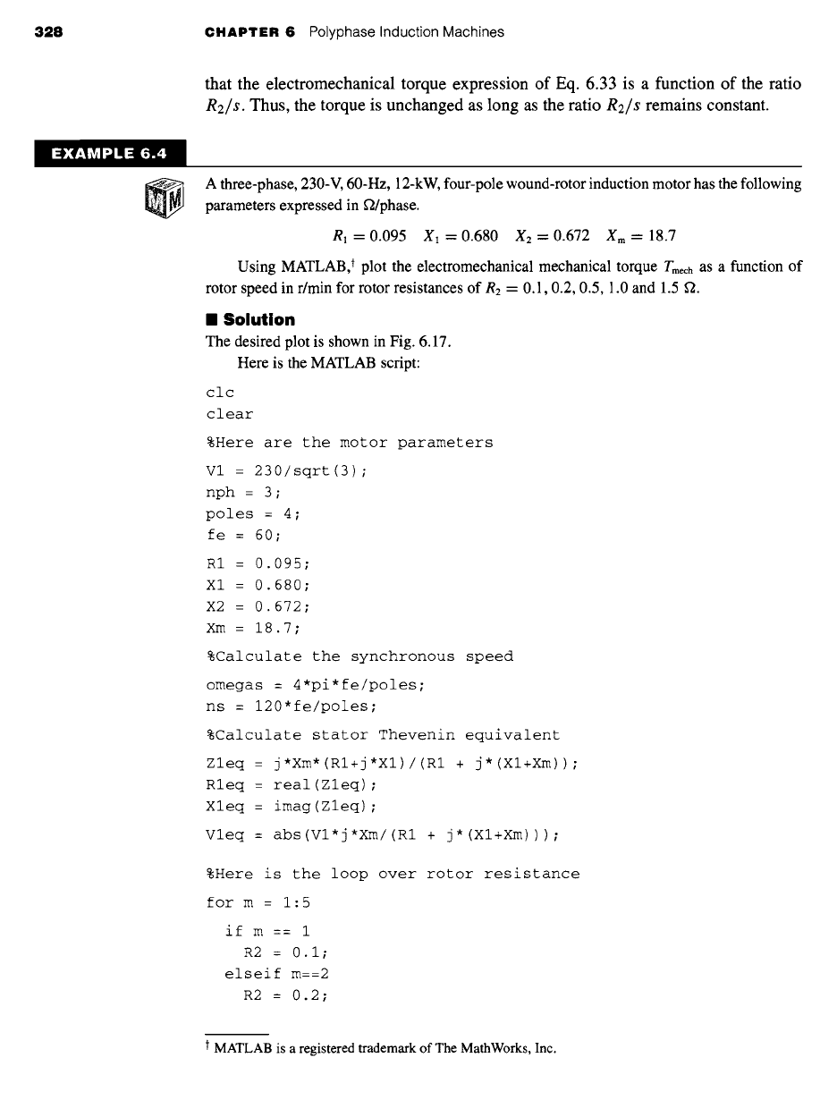
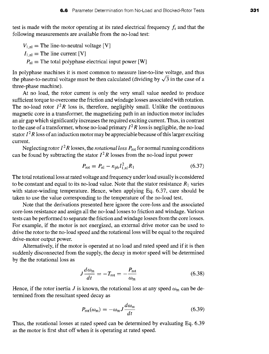
A three-phase, 230-V, 60-Hz, 12-kW, four-pole wound-rotor induction motor has the following
parameters expressed in f2/phase.
R1=0.095 X1=0.680 X2=0.672 Xm=18.7
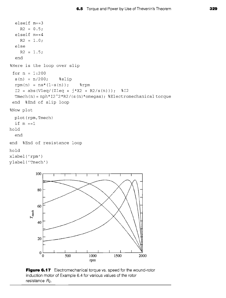
Using MATLAB: plot the electromechanical mechanical torque Tmech as a function of
rotor speed in r/min for rotor resistances of R2 = 0.1, 0.2, 0.5, 1.0 and 1.5 ft.
II Solution
The desired plot is shown in Fig. 6.17.
Here is the MATLAB script:
clc
clear
%Here are the motor parameters
V1 = 230/sqrt(3) ;
nph = 3 ;
poles = 4 ;
fe = 60 ;
R1 = 0.095;
Xl = 0. 680;
X2 = 0.672;
Xm = 18.7;
%Calculate the synchronous speed
omegas = 4*pi*fe/poles;
ns = 120*fe/poles;
%Calculate stator Thevenin equivalent
Zleq : j*Xm*(ml+j*Xl)/(ml + j*(Xl+Xm)) ;
Rleq = real(Zleq) ;
Xleq = imag(Zleq) ;
Vleq = abs(Vl*j*Xm/(Rl + j*(XI+Xm))) ;
%Here is the loop over rotor resistance
for m : 1:5
if m == 1
R2 = 0.i;
elseif m==2
R2 = 0.2;
t MATLAB is a registered trademark of The MathWorks, Inc.
6.5 Torque and Power by Use of Thevenin's Theorem 329
elseif m==3
R2 = 0.5;
elseif m==4
R2 = 1.0;
else
R2 = 1.5;
end
%Here is the loop over slip
for n : 1:200
s(n) : n/200; %slip
rpm(n) = ns*(l-s(n)); %rpm
I2 : abs(Vleq/(Zleq + j'X2 + R2/s(n))) ; %I2
Tmech(n) = nph*I2^2*R2/(s(n)*omegas); %Electromechanical torque
end %End of slip loop
%Now plot
plot (rpm, Tmech)
if m ==i
hold
end
end %End of resistance loop
hold
xlabel ( ' rpm' )
ylabel ('Tmech')
100
80
60
40
20
0
0
I I I I I I I I
500 1000 1500 2000
I I I I I I I I
rpm
Figure 6.17 Electromechanical torque vs. speed for the wound-rotor
induction motor of Example 6.4 for various values of the rotor
resistance R2.
330 CHAPTER
6 Polyphase Induction Machines
Calculate the electromechanical mechanical torque for the motor of Example 6.4 assuming a
rotor resistance of 0.3 ~ and a motor speed of 1719 r/min.
Solution
36.8 N. m
In applying the induction-motor equivalent circuit, the idealizations on which it
is based should be kept in mind. This is particularly necessary when investigations
are carried out over a wide speed range, such as is the case in investigations of motor
starting. Saturation under the heavy inrush currents associated with starting conditions
has a significant effect on the motor reactances. Moreover, the rotor currents are at
slip frequency, which varies from stator frequency at zero speed to a low value at
full-load speed. The current distribution in the rotor bars of squirrel-cage motors
may vary significantly with frequency, giving rise to significant variations in rotor
resistance. In fact, as discussed in Sections 6.7.2 and 6.7.3, motor designers can
tailor the shape of the rotor bars in squirrel-cage motors to obtain various speed-
torque characteristics. Errors from these causes can be kept to a minimum by using
equivalent-circuit parameters corresponding as closely as possible to those of the
proposed operating conditions. 1
6.6
PARAMETER DETERMINATION FROM
NO-LOAD AND BLOCKED-ROTOR TESTS
The equivalent-circuit parameters needed for computing the performance of a poly-
phase induction motor under load can be obtained from the results of a no-load test,
a blocked-rotor test, and measurements of the dc resistances of the stator windings.
Stray-load losses, which must be taken into account when accurate values of efficiency
are to be calculated, can also be measured by tests which do not require loading the
motor. The stray-load-loss tests are not described here, however. 2
6.6.1 No.Load Test
Like the open-circuit test on a transformer, the
no-load test
on an induction motor gives
information with respect to exciting current and no-load losses. This test is ordinarily
performed at rated frequency and with balanced polyphase voltages applied to the
stator terminals. Readings are taken at rated voltage, after the motor has been running
long enough for the bearings to be properly lubricated. We will assume that the no-load
I See, for instance, R. E Horrell and W. E. Wood, "A Method of Determining Induction Motor
Speed-Torque-Current Curves from Reduced Voltage Tests,"
Trans. AIEE,
73(3):670-674 (1954).
2 For information concerning test methods, see IEEE Std. 112-1996, "Test Procedures for Polyphase
Induction Motors and Generators," Institute of Electrical and Electronics Engineers, Inc., 345 East 47th
Street, New York, New York, 10017.
6,6
Parameter Determination from No-Load and Blocked-Rotor Tests
331
test is made with the motor operating at its rated electrical frequency fr and that the
following measurements are available from the no-load test:
Vl,nl - The line-to-neutral voltage [V]
II,nl -- The line current [V]
Pnl --
The total polyphase electrical input power [W]
In polyphase machines it is most common to measure line-to-line voltage, and thus
the phase-to-neutral voltage must be then calculated (dividing by ~/3 in the case of a
three-phase machine).
At no load, the rotor current is only the very small value needed to produce
sufficient torque to overcome the friction and windage losses associated with rotation.
The no-load rotor
IZR
loss is, therefore, negligibly small. Unlike the continuous
magnetic core in a transformer, the magnetizing path in an induction motor includes
an air gap which significantly increases the required exciting current. Thus, in contrast
to the case of a transformer, whose no-load primary 12 R loss is negligible, the no-load
stator I 2 R loss of an induction motor may be appreciable because of this larger exciting
current.
Neglecting rotor I 2 R losses, the
rotational loss
Prot for normal running conditions
can be found by subtracting the stator
IZR
losses from the no-load input power
Prot -- Pnl - nph
I2,n 1R
1 (6.37)
The total rotational loss at rated voltage and frequency under load usually is considered
to be constant and equal to its no-load value. Note that the stator resistance R1 varies
with stator-winding temperature. Hence, when applying Eq. 6.37, care should be
taken to use the value corresponding to the temperature of the no-load test.
Note that the derivations presented here ignore the core-loss and the associated
core-loss resistance and assign all the no-load losses to friction and windage. Various
tests can be performed to separate the friction and windage losses from the core losses.
For example, if the motor is not energized, an external drive motor can be used to
drive the rotor to the no-load speed and the rotational loss will be equal to the required
drive-motor output power.
Alternatively, if the motor is operated at no load and rated speed and if it is then
suddenly disconnected from the supply, the decay in motor speed will be determined
by the the rotational loss as
doom Prot
J~ = -Trot = (6.38)
dt 09 m
Hence, if the rotor inertia J is known, the rotational loss at any speed
(-Om
can be de-
termined from the resultant speed decay as
doom
Prot(O)m) -- --O)mJ~ (6.39)
dt
Thus, the rotational losses at rated speed can be determined by evaluating Eq. 6.39
as the motor is first shut off when it is operating at rated speed.
332 CHAPTER 6 Polyphase Induction Machines
If the no-load rotational losses are determined in this fashion, the core loss can
be determined as
Pcore = Pnl- Prot-
nphI?,nlR1
(6.40)
Here Pcore is the total
no-load core loss
corresponding to the voltage of the no-load
test (typically rated voltage).
Under no-load conditions, the stator current is relatively low and, to a first approx-
imation, one can neglect the corresponding voltage drop across the stator resistance
and leakage reactance. Under this approximation, the voltage across the core-loss re-
sistance will be equal to the no-load line-to-neutral voltage and the core-loss resistance
can be determined as
gc
=
nph V12nl
(6.41)
Pcore
Provided that the machine is operated close to rated speed and rated voltage, the
refinement associated with separating out the core loss and specifically incorporating it
in the form of a core-loss resistance in the equivalent circuit will not make a significant
difference in the results of an analysis. Hence, it is common to ignore the core-loss
resistance and to simply include the core losses with the rotational losses. For the
purposes of analytical simplicity, this approach will be followed in the remainder of
the text. However, if necessary, the reader should find it relatively straight forward to
modify the remaining derivations to appropriately include the core-loss resistance.
Because the slip at no load, Snl, is very small, the reflected rotor resistance R2/Snl is
very large. The parallel combination of rotor and magnetizing branches then becomes
j Xm shunted by the rotor leakage reactance X2 in series with a very high resistance,
and the reactance of this parallel combination therefore very nearly equals Xm. Con-
sequently the apparent reactance Xnl measured at the stator terminals at no load very
nearly equals X~ + Xm, which is the self-reactance X1~ of the stator; i.e.,
Xnl = Xll = XI -~- Xm
(6.42)
The self-reactance of the stator can therefore be determined from the no-load
measurements. The reactive power at no load Qnl can be determined as
Qnl = v/S21- p2 (6.43)
where
Snl -- nph Vl,nlll,nl
(6.44)
is the total apparent power input at no load.
The no-load reactance Xnl can then be calculated from Onl and ll,nl as
anl
Xnl -- 12
(6.45)
nph l,nl
Usually the no-load power factor is small (i.e.,
anl
>>
enl) SO
that the no-load
6.6
Parameter Determination from No-Load and Blocked-Rotor Tests 333
reactance very nearly equals the no-load impedance.
Vl,nl
Xnl ~ (6.46)
II,nl
6.6.2 Blocked.Rotor Test
Like the short-circuit test on a transformer, the
blocked-rotor test
on an induction motor
gives information with respect to the leakage impedances. The rotor is blocked so that
it cannot rotate (hence the slip is equal to unity), and balanced polyphase voltages are
applied to the stator terminals. We will assume that the following measurements are
available from the blocked-rotor test:
Vl,bl = The line-to-neutral voltage [V]
II,bl --
The line current [V]
Pbl -- The total polyphase electrical input power [W]
fbl = The frequency of the blocked-rotor test [Hz]
In some cases, the blocked-rotor torque also is measured.
The equivalent circuit for blocked-rotor conditions is identical to that of a short-
circuited transformer. An induction motor is more complicated than a transformer,
however, because its leakage impedance may be affected by magnetic saturation of
the leakage-flux paths and by rotor frequency. The blocked-rotor impedance may also
be affected by rotor position, although this effect generally is small with squirrel-cage
rotors.
The guiding principle is that the blocked-rotor test should be performed under
conditions for which the current and rotor frequency are approximately the same as
those in the machine at the operating condition for which the performance is later to
be calculated. For example, if one is interested in the characteristics at slips near unity,
as in starting, the blocked-rotor test should be taken at normal frequency and with
currents near the values encountered in starting. If, however, one is interested in normal
running characteristics, the blocked-rotor test should be taken at a reduced voltage
which results in approximately rated current; the frequency also should be reduced,
since the values of rotor effective resistance and leakage inductance at the low rotor
frequencies corresponding to small slips may differ appreciably from their values at
normal frequency, particularly with double-cage or deep-bar rotors, as discussed in
Section 6.7.2.
IEEE Standard 112 suggests a blocked-rotor test frequency of 25 percent of
rated frequency. The total leakage reactance at normal frequency can be obtained
from this test value by considering the reactance to be proportional to frequency. The
effects of frequency often are negligible for normal motors of less than 25-hp rating,
and the blocked impedance can then be measured directly at normal frequency. The
importance of maintaining test currents near their rated value stems from the fact that
these leakage reactances are significantly affected by saturation.
Based upon blocked-rotor measurements, the blocked-rotor reactance can be
found from the blocked-rotor reactive power
Qbl = ~/S~I-
p2 (6.47)
334 CHAPTER 6 Polyphase Induction Machines
where
Sbl "-- nph Vl,blll,bl
(6.48)
is the total blocked-rotor apparent power. The blocked-rotor reactance, corrected to
rated frequency, can then be calculated as
Xbl ~ Tbl nph 1,bl
12 (6.49)
The blocked-rotor resistance can be calculated from the blocked-rotor input
power as
Pbl
Rbl =
12 (6.50)
np h 1,bl
Once these parameters have been determined, the equivalent circuit parameters
can be determined. Under blocked-rotor conditions, an expression for the stator input
impedance can be obtained from examination of Fig. 6.11 a (with s = 1) as
Zbl -- gl + jX1 + (R2 + jX2)
in parallel with
jXm
( )
-" R1 + R2 R2 + (X m + 22)2
( Xm(RE + Xz(Xm + X2)) )
Here we have assumed that the reactances are at their rated-frequency values. Making
appropriate approximations (e.g., assuming R2 << Xm), Eq. 6.51 can be reduced to
Zbl =
gl + RE 22 + Xm + j X1 + X2 Xe + Xm (6.52)
Thus the apparent resistance under blocked-rotor conditions is given by
Rbl = RI + R2 X2 +
Xm (6.53)
and the apparent rated-frequency blocked-rotor reactance by
Xbl = X 1 -~- X 2 X2 -+- Xm
(6.54)
From Eqs. 6.54 and 6.53, the rotor leakage reactance X2 and resistance R2 can
be found as
( Xm ) (6.55)
X2 = (Xbl- X l) Xm -~- X l - Xbl
and
N2 ~ (gbl-- gl) (X2"~-Xm) 2
Xm (6.56)
6,6 Parameter Determination from No-Load and Blocked-Rotor Tests 335
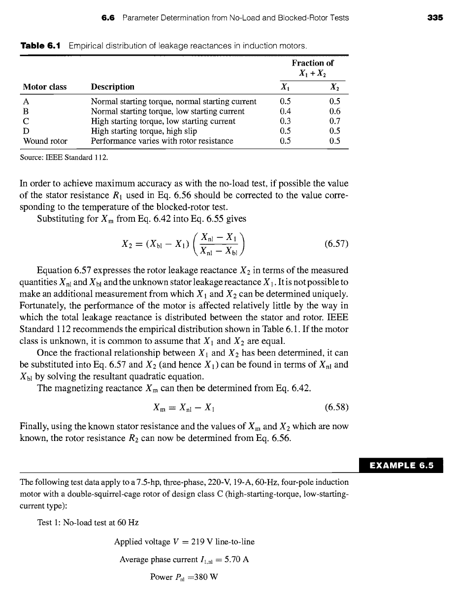
Table
6.1 Empirical distribution of leakage reactances in induction motors.
Iltlll! ~. .
Fraction
of
X 1 q- X 2
Motor class Description X~ X2
A
B
C
D
Wound rotor
Normal starting torque, normal starting current 0.5 015
Normal starting torque, low starting current 0.4 0.6
High starting torque, low starting current 0.3 0.7
High starting torque, high slip 0.5 0.5
Performance varies with rotor resistance 0.5 0.5
Source: IEEE Standard 112.
In order to achieve maximum accuracy as with the no-load test, if possible the value
of the stator resistance R1 used in Eq. 6.56 should be corrected to the value corre-
sponding to the temperature of the blocked-rotor test.
Substituting for Xm from Eq. 6.42 into Eq. 6.55 gives
(Xnl- X1) (6.57)
X2 -- (Xbl- X1) Xn 1 - Xbl
Equation 6.57 expresses the rotor leakage reactance X2 in terms of the measured
quantities
Xnl
and
Xbl
and the unknown stator leakage reactance X1. It is not possible to
make an additional measurement from which X1 and X2 can be determined uniquely.
Fortunately, the performance of the motor is affected relatively little by the way in
which the total leakage reactance is distributed between the stator and rotor. IEEE
Standard 112 recommends the empirical distribution shown in Table 6.1. If the motor
class is unknown, it is common to assume that X1 and X2 are equal.
Once the fractional relationship between X1 and
X2
has been determined, it can
be substituted into Eq. 6.57 and X2 (and hence XI) can be found in terms of Xnl and
Xbl by solving the resultant quadratic equation.
The magnetizing reactance Xm can then be determined from Eq. 6.42.
Xm --- Xnl- X1
(6.58)
Finally, using the known stator resistance and the values of Xm and X2 which are now
known, the rotor resistance R2 can now be determined from Eq. 6.56.
The following test data apply to a 7.5-hp, three-phase, 220-V, 19-A, 60-Hz, four-pole induction
motor with a double-squirrel-cage rotor of design class C (high-starting-torque, low-starting-
current type):
Test 1: No-load test at 60 Hz
Applied voltage V = 219 V line-to-line
Average phase current Ii,nl = 5.70 A
Power Pnl =380 W
EXAMPLE 6.5