Fitzgerald A.E. Electric Machinery
Подождите немного. Документ загружается.

356 CHAPTER 6 Polyphase Induction Machines
6.28 Neglecting any effects of rotational and core losses, use MATLAB to plot the
internal torque versus speed curve for the induction motor of Problem 6.10
for rated-voltage, rated-frequency operation. On the same plot, plot curves of
internal torque versus speed for this motor assuming the rotor resistance
increases by a factor of 2, 5 and 10.
6.29 A 100-kW, three-phase, 60-Hz, 460-V, six-pole wound-rotor induction motor
develops its rated full-load output at a speed of 1158 r/min when operated at
rated voltage and frequency with its slip rings short-circuited. The maximum
torque it can develop at rated voltage and frequency is 310 percent of full-load
torque. The resistance of the rotor winding is 0.17 S2/phase Y. Neglect any
effects of rotational and stray-load loss and stator resistance.
a. Compute the rotor I2R loss at full load.
b. Compute the speed at maximum torque in r/min.
c. How much resistance must be inserted in series with the rotor windings
to produce maximum starting torque?
With the rotor windings short-circuited, the motor is now run from a
50-Hz supply with the applied voltage adjusted so that the air-gap flux wave
is essentially equal to that at rated 60-Hz operation.
d. Compute the 50-Hz applied voltage.
e. Compute the speed at which the motor will develop a torque equal to its
rated 60-Hz value with its slip-tings shorted.
6.30 A 460-V, three-phase, six-pole, 60-Hz, 150-kW, wound-rotor induction motor
develops an internal torque of 190 percent with a line current of 200 percent
(torque and current expressed as a percentage of their full-load values) at a
slip of 5.6 percent when running at rated voltage and frequency with its rotor
terminals short-circuited. The rotor resistance is measured to be 90 mfl
between each slip ring and may be assumed to remain constant. A balanced
set of Y-connected resistors is to be connected to the slip rings in order to
limit the rated-voltage starting current to 200 percent of its rated value. What
resistance must be chosen for each leg of the Y connection? What will be the
starting torque under these conditions?
6.31 The resistance measured between each pair of slip rings of a three-phase,
60-Hz, 250-kW, 16-pole, wound-rotor induction motor is 49 mfl. With the
slip tings short-circuited, the full-load slip is 0.041. For the purposes of this
problem, it may be assumed that the slip-torque curve is a straight line from
no load to full load. The motor drives a fan which requires 250 kW at the
full-load speed of the motor. Assuming the torque to drive the fan varies as
the square of the fan speed, what resistance should be connected in series
with the rotor resistance to reduce the fan speed to 400 ffmin?
DC Machines
p
c machines are characterized by their versatility. By means of various com-
binations of shunt-, series-, and separately-excited field windings they can be
designed to display a wide variety of volt-ampere or speed-torque character-
istics for both dynamic and steady-state operation. Because of the ease with which
they can be controlled, systems of dc machines have been frequently used in appli-
cations requiring a wide range of motor speeds or precise control of motor output. In
recent years, solid-state ac drive system technology has developed sufficiently that
these systems are replacing dc machines in applications previously associated almost
exclusively with dc machines. However, the versatility of dc machines in combination
with the relative simplicity of their drive systems will insure their continued use in a
wide variety of applications.
7.1 INTRODUCTION
The essential features of a dc machine are shown schematically in Fig. 7.1. The stator
has salient poles and is excited by one or more field coils. The air-gap flux distribution
created by the field windings is symmetric about the center line of the field poles.
This axis is called the
field axis
or
direct axis.
As discussed in Section 4.6.2, the ac voltage generated in each rotating arma-
ture coil is converted to dc in the external armature terminals by means of a rotating
commutator and stationary brushes to which the armature leads are connected. The
commutator-brush combination forms a mechanical rectifier, resulting in a dc arma-
ture voltage as well as an armature-mmf wave which is fixed in space. Commutator
action is discussed in detail in Section 7.2.
The brushes are located so that commutation occurs when the coil sides are in the
neutral zone, midway between the field poles. The axis of the armature-mmf wave then
is 90 electrical degrees from the axis of the field poles, i.e., in the
quadrature axis.
In
the schematic representation of Fig. 7.1 a, the brushes are shown in the quadrature axis
357
358 CHAPTER 7 DC Machines
Onnclrnhlro
Direct
Brushes axis
Field
ield
oil
Armature
coils
(a) (b)
Figure
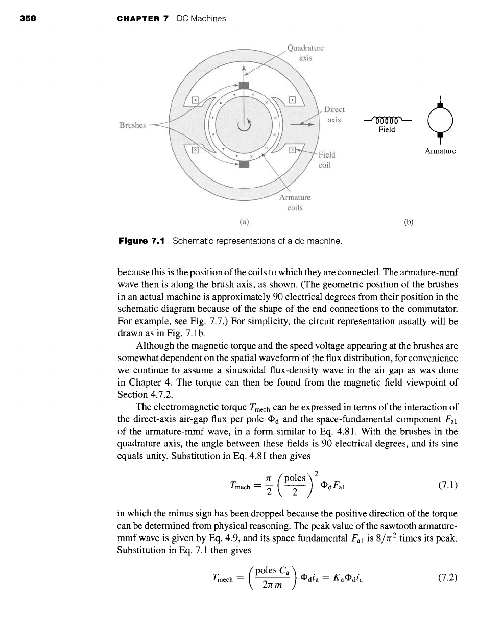
7.1 Schematic representations of a dc machine.
because this is the position of the coils to which they are connected. The armature-mmf
wave then is along the brush axis, as shown. (The geometric position of the brushes
in an actual machine is approximately 90 electrical degrees from their position in the
schematic diagram because of the shape of the end connections to the commutator.
For example, see Fig. 7.7.) For simplicity, the circuit representation usually will be
drawn as in Fig. 7.1 b.
Although the magnetic torque and the speed voltage appearing at the brushes are
somewhat dependent on the spatial waveform of the flux distribution, for convenience
we continue to assume a sinusoidal flux-density wave in the air gap as was done
in Chapter 4. The torque can then be found from the magnetic field viewpoint of
Section 4.7.2.
The electromagnetic torque Tmech can be expressed in terms of the interaction of
the direct-axis air-gap flux per pole ~d and the space-fundamental component Fal
of the armature-mmf wave, in a form similar to Eq. 4.81. With the brushes in the
quadrature axis, the angle between these fields is 90 electrical degrees, and its sine
equals unity. Substitution in Eq. 4.81 then gives
7r (p°les) 2
Tmech -- ~- 2 ~d Fal (7.1)
in which the minus sign has been dropped because the positive direction of the torque
can be determined from physical reasoning. The peak value of the sawtooth armature-
mmf wave is given by Eq. 4.9, and its space fundamental Fal is 8/zr 2 times its peak.
Substitution in Eq. 7.1 then gives
Tmech'-(p°lesCa) ~dia-Kadpdia2rrm
(7.2)
7.1 Introduction 359
Brush
voltage e a
X
~) Rectified
coilvoltages
t
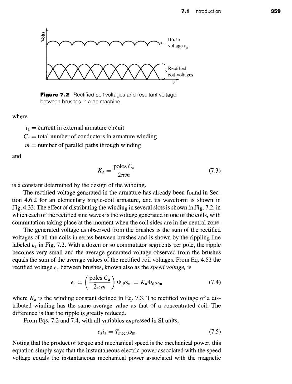
Figure 7.2
Rectified coil voltages and resultant voltage
between brushes in a dc machine.
where
and
ia -- current in external armature circuit
Ca "-"
total number of conductors in armature winding
m - number of parallel paths through winding
poles
Ca
ga = (7.3)
27rm
is a constant determined by the design of the winding.
The rectified voltage generated in the armature has already been found in Sec-
tion 4.6.2 for an elementary single-coil armature, and its waveform is shown in
Fig. 4.33. The effect of distributing the winding in several slots is shown in Fig. 7.2, in
which each of the rectified sine waves is the voltage generated in one of the coils, with
commutation taking place at the moment when the coil sides are in the neutral zone.
The generated voltage as observed from the brushes is the sum of the rectified
voltages of all the coils in series between brushes and is shown by the rippling line
labeled
ea
in Fig. 7.2. With a dozen or so commutator segments per pole, the ripple
becomes very small and the average generated voltage observed from the brushes
equals the sum of the average values of the rectified coil voltages. From Eq. 4.53 the
rectified voltage ea between brushes, known also as the
speed voltage,
is
(p°les Ca) ~dC0m -- Ka~dC0 m (7.4)
ea -- 2zrm
where
Ka
is the winding constant defined in Eq. 7.3. The rectified voltage of a dis-
tributed winding has the same average value as that of a concentrated coil. The
difference is that the ripple is greatly reduced.
From Eqs. 7.2 and 7.4, with all variables expressed in SI units,
eaia--
TmechO)m
(7.5)
Noting that the product of torque and mechanical speed is the mechanical power, this
equation simply says that the instantaneous electric power associated with the speed
voltage equals the instantaneous mechanical power associated with the magnetic
360 CHAPTER 7 DC Machines
~d
Air-gap -,~--'
ZNfif
ea0
Air-gap
-~//f
Speed -- Ogmo
ENfif
(a) (b)
ea0
//
Air-gap
----~/Y
Speed = O)m0
r
tf
(c)
Figure
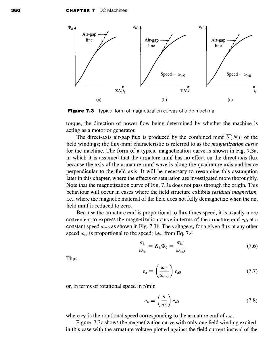
7.3 Typical form of magnetization curves of a dc machine.
torque, the direction of power flow being determined by whether the machine is
acting as a motor or generator.
The direct-axis air-gap flux is produced by the combined mmf ~ Nfif of the
field windings; the flux-mmf characteristic is referred to as the magnetization curve
for the machine. The form of a typical magnetization curve is shown in Fig. 7.3a,
in which it is assumed that the armature mmf has no effect on the direct-axis flux
because the axis of the armature-mmf wave is along the quadrature axis and hence
perpendicular to the field axis. It will be necessary to reexamine this assumption
later in this chapter, where the effects of saturation are investigated more thoroughly.
Note that the magnetization curve of Fig. 7.3a does not pass through the origin. This
behaviour will occur in cases where the field structure exhibits residual magnetism,
i.e., where the magnetic material of the field does not fully demagnetize when the net
field mmf is reduced to zero.
Because the armature emf is proportional to flux times speed, it is usually more
convenient to express the magnetization curve in terms of the armature emf ea0 at a
constant speed Wm0 as shown in Fig. 7.3b. The voltage ea for a given flux at any other
speed
O-)m is
proportional to the speed; i.e., from Eq. 7.4
ea ea0
-- Ka~d --
(7.6)
O)m Ogm0
Thus
ea-- -- ea0
(7.7)
O)m0
or, in terms of rotational speed in r/min
(n)
ea -- -- eao
no
(7.8)
where no is the rotational speed corresponding to the armature emf of
ea0.
Figure 7.3c shows the magnetization curve with only one field winding excited,
in this case with the armature voltage plotted against the field current instead of the
7.1 Introduction 361
field ampere-turns. This curve can easily be obtained by test methods; since the field
current can be measured directly, no knowledge of any design details is required.
Over a fairly wide range of excitation the reluctance of the electrical steel in the
machine is negligible compared with that of the air gap. In this region the flux is
linearly proportional to the total mmf of the field windings, the constant of propor-
tionality being the direct-axis permeance/gd; thus
fYPd --- ~')d Z Nfif
(7.9)
The dashed straight line through the origin coinciding with the straight portion of the
magnetization curves in Fig. 7.3 is called the air-gap line. This nomenclature refers
to the fact that this linear magnetizing characteristic would be found if the reluctance
of the magnetic material portion of the flux path remained negligible compared to that
of the air gap, independent of the degree of magnetic saturation of the motor steel.
The outstanding advantages of dc machines arise from the wide variety of oper-
ating characteristics which can be obtained by selection of the method of excitation of
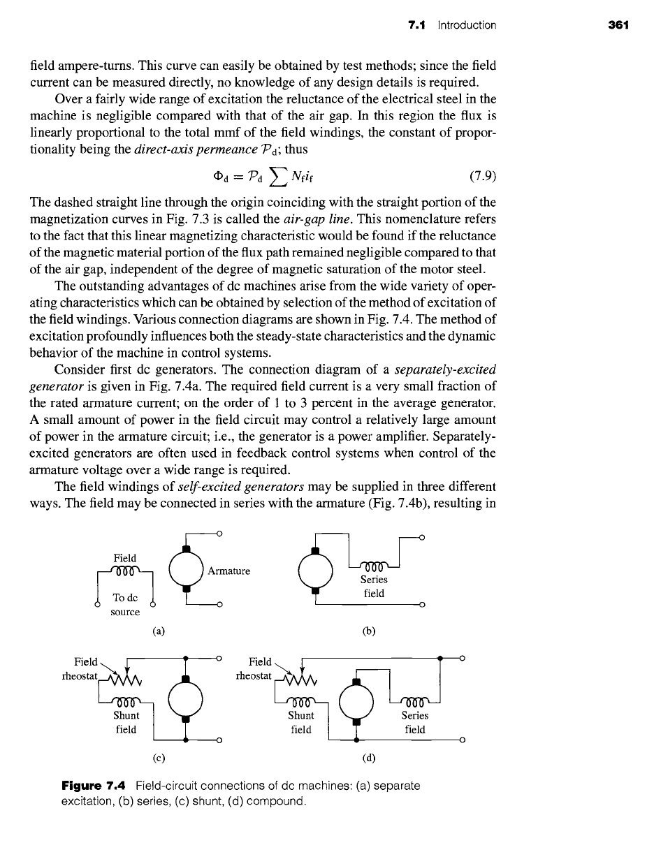
the field windings. Various connection diagrams are shown in Fig. 7.4. The method of
excitation profoundly influences both the steady-state characteristics and the dynamic
behavior of the machine in control systems.
Consider first dc generators. The connection diagram of a separately-excited
generator is given in Fig. 7.4a. The required field current is a very small fraction of
the rated armature current; on the order of 1 to 3 percent in the average generator.
A small amount of power in the field circuit may control a relatively large amount
of power in the armature circuit; i.e., the generator is a power amplifier. Separately-
excited generators are often used in feedback control systems when control of the
armature voltage over a wide range is required.
The field windings of self-excited generators may be supplied in three different
ways. The field may be connected in series with the armature (Fig. 7.4b), resulting in
o
Field
Armature
o
source
o
(a) (b)
Field Field ~ ~
o
rheostat rheostat
field ~ Sf~e~dt Sf~il7
.. O
(c) (d)
Figure 7.4
Field-circuit connections of dc machines: (a) separate
excitation, (b) series, (c) shunt, (d) compound.
362 CHAPTER 7 DC Machines
0
100
o 75
~ 50
~b
N 25
t
Shunt
Separatel~
....--
-- =-"--- ------ - .........
m •
i
i
i
- /
I
I
I
/ I I I I
r
0 25 50 75 100
Load current in percent of rating
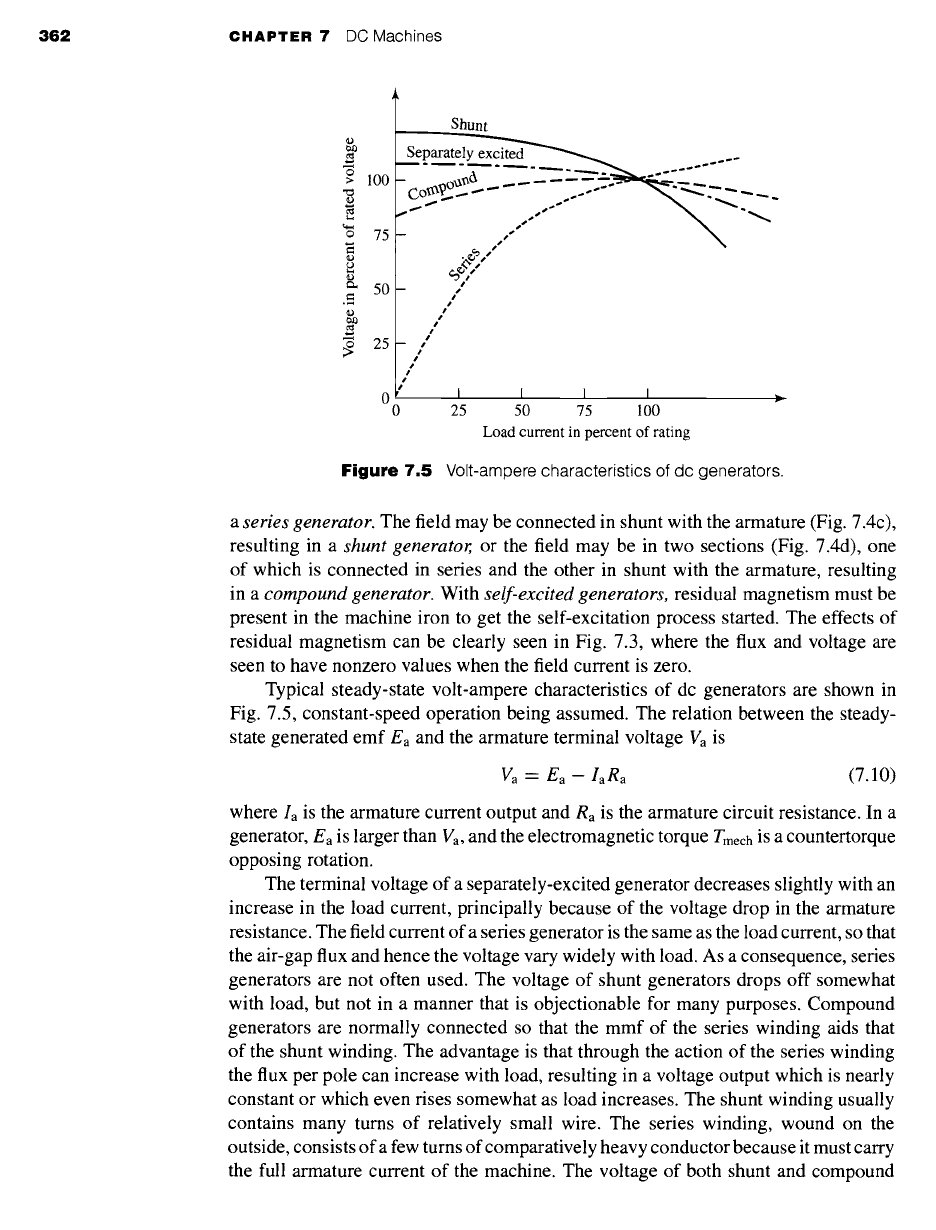
Figure 7.5 Volt-ampere characteristics of dc generators.
a series generator.
The field may be connected in shunt with the armature (Fig. 7.4c),
resulting in a
shunt generator,
or the field may be in two sections (Fig. 7.4d), one
of which is connected in series and the other in shunt with the armature, resulting
in a
compound generator.
With
self-excited generators,
residual magnetism must be
present in the machine iron to get the self-excitation process started. The effects of
residual magnetism can be clearly seen in Fig. 7.3, where the flux and voltage are
seen to have nonzero values when the field current is zero.
Typical steady-state volt-ampere characteristics of dc generators are shown in
Fig. 7.5, constant-speed operation being assumed. The relation between the steady-
state generated emf Ea and the armature terminal voltage Va is
Va - Ea- taRa
(7.10)
where la is the armature current output and
Ra
is the armature circuit resistance. In a
generator, Ea is larger than Va, and the electromagnetic torque Tmech is a countertorque
opposing rotation.
The terminal voltage of a separately-excited generator decreases slightly with an
increase in the load current, principally because of the voltage drop in the armature
resistance. The field current of a series generator is the same as the load current, so that
the air-gap flux and hence the voltage vary widely with load. As a consequence, series
generators are not often used. The voltage of shunt generators drops off somewhat
with load, but not in a manner that is objectionable for many purposes. Compound
generators are normally connected so that the mmf of the series winding aids that
of the shunt winding. The advantage is that through the action of the series winding
the flux per pole can increase with load, resulting in a voltage output which is nearly
constant or which even rises somewhat as load increases. The shunt winding usually
contains many turns of relatively small wire. The series winding, wound on the
outside, consists of a few turns of comparatively heavy conductor because it must carry
the full armature current of the machine. The voltage of both shunt and compound
7.1 Introduction 363
%-.
o 100
75
~ 5o-
~ 25-
OUnc 1
Shunt ~
-
_ ~ "~
%
%
%,
0 I I I I
0 25 50 75 100
Load torque in percent of rating
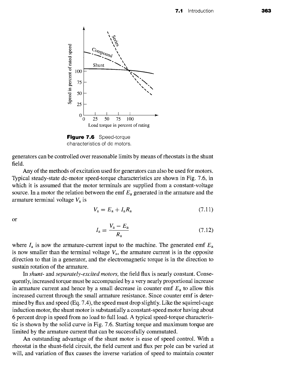
Figure 7.6
Speed-torque
characteristics of dc motors.
generators can be controlled over reasonable limits by means of rheostats in the shunt
field.
Any of the methods of excitation used for generators can also be used for motors.
Typical steady-state dc-motor speed-torque characteristics are shown in Fig. 7.6, in
which it is assumed that the motor terminals are supplied from a constant-voltage
source. In a motor the relation between the emf Ea generated in the armature and the
armature terminal voltage Va is
Va = Ea + IaR.
(7.11)
or
Va m Ea
Ia - (7.12)
Ra
where Ia is now the armature-current input to the machine. The generated emf Ea
is now smaller than the terminal voltage Va, the armature current is in the opposite
direction to that in a generator, and the electromagnetic torque is in the direction to
sustain rotation of the armature.
In
shunt-
and
separately-excited motors,
the field flux is nearly constant. Conse-
quently, increased torque must be accompanied by a very nearly proportional increase
in armature current and hence by a small decrease in counter emf Ea to allow this
increased current through the small armature resistance. Since counter emf is deter-
mined by flux and speed (Eq. 7.4), the speed must drop slightly. Like the squirrel-cage
induction motor, the shunt motor is substantially a constant-speed motor having about
6 percent drop in speed from no load to full load. A typical speed-torque characteris-
tic is shown by the solid curve in Fig. 7.6. Starting torque and maximum torque are
limited by the armature current that can be successfully commutated.
An outstanding advantage of the shunt motor is ease of speed control. With a
rheostat in the shunt-field circuit, the field current and flux per pole can be varied at
will, and variation of flux causes the inverse variation of speed to maintain counter
364 CHAPTER 7
DC Machines
emf approximately equal to the impressed terminal voltage. A maximum speed range
of about 4 or 6 to 1 can be obtained by this method, the limitation again being
commutating conditions. By variation of the impressed armature voltage, very wide
speed ranges can be obtained.
In the
series motor,
increase in load is accompanied by increases in the arma-
ture current and mmf and the stator field flux (provided the iron is not completely
saturated). Because flux increases with load, speed must drop in order to maintain
the balance between impressed voltage and counter emf; moreover, the increase in
armature current caused by increased torque is smaller than in the shunt motor be-
cause of the increased flux. The series motor is therefore a varying-speed motor with
a markedly drooping speed-torque characteristic of the type shown in Fig. 7.6. For
applications requiting heavy torque overloads, this characteristic is particularly ad-
vantageous because the corresponding power overloads are held to more reasonable
values by the associated speed drops. Very favorable starting characteristics also result
from the increase in flux with increased armature current.
In the
compound motor,
the series field may be connected either
cumulatively,
so
that its mmf adds to that of the shunt field, or
differentially,
so that it opposes. The
differential connection is rarely used. As shown by the broken-dash curve in Fig. 7.6,
a cumulatively-compounded motor has speed-load characteristics intermediate be-
tween those of a shunt and a series motor, with the drop of speed with load depending
on the relative number of ampere-tums in the shunt and series fields. It does not have
the disadvantage of very high light-load speed associated with a series motor, but it
retains to a considerable degree the advantages of series excitation.
The application advantages of dc machines lie in the variety of performance
characteristics offered by the possibilities of shunt, series, and compound excitation.
Some of these characteristics have been touched upon briefly in this section. Still
greater possibilities exist if additional sets of brushes are added so that other voltages
can be obtained from the commutator. Thus the versatility of dc-machine systems and
their adaptability to control, both manual and automatic, are their outstanding features.
7.2 COMMUTATOR ACTION
The dc machine differs in several respects from the ideal model of Section 4.2.2.
Although the basic concepts of Section 4.2.2 are still valid, a reexamination of the
assumptions and a modification of the model are desirable. The crux of the matter is
the effect of the commutator shown in Figs. 4.2 and 4.16.
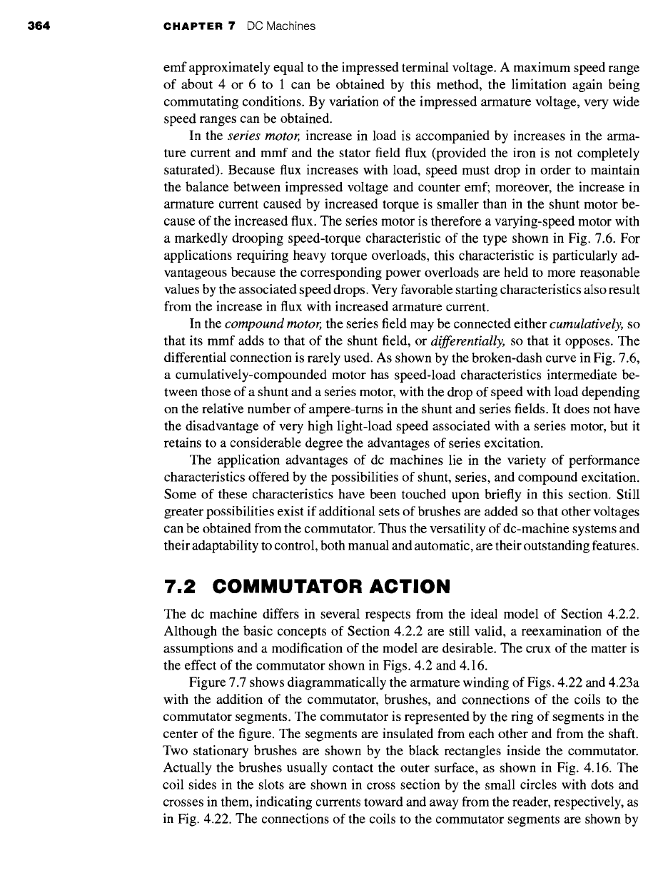
Figure 7.7 shows diagrammatically the armature winding of Figs. 4.22 and 4.23a
with the addition of the commutator, brushes, and connections of the coils to the
commutator segments. The commutator is represented by the ring of segments in the
center of the figure. The segments are insulated from each other and from the shaft.
Two stationary brushes are shown by the black rectangles inside the commutator.
Actually the brushes usually contact the outer surface, as shown in Fig. 4.16. The
coil sides in the slots are shown in cross section by the small circles with dots and
crosses in them, indicating currents toward and away from the reader, respectively, as
in Fig. 4.22. The connections of the coils to the commutator segments are shown by
7.2 Commutator Action 365
V1
~!ii!!~i~i!~i!~!iii!iii~iiiiiii!!!i~iiii~iJiiJJ~i!iiiii!~ii~i~i~ii~ii~i~iii~ii~i~i~i~i~iJi~iiJ .... /
V
~!~i~i~i~i~i~i!ii!!i~iii!i~}ii!iii!i~ii}i~}~!ii!iii~iiiii!ii~i~i~iii~i~!i!i~i~ii~ ~¸ /
i iiji:i Yli}iiiii:'i}i}iiiiiiiii/!i!}!iii}iiiii}i}i}ii}ii i: 10 /
f /
iiii!iiiii::i!iiiii;iliiii!!ii!iiiilililiiiiiiiiii ;;ill i!il iiiiiii iiiiiiiiiiii!!!i!iiiiiiiiiii!iiiiiii I
i..i iiiii!i!iiiiiii!ii ii!ii
9,,
NI
i Magnetic axis
of armature
12..__ ___.... 1
i
11 ¢--' ~
NN2
/ .).
7 "'6
(a)
\\
Field coil
NI
V1
NI
T
/// \\
/
i\
IQ® ~'. ~bll ->-/a~X A
(b)
j j
/
//
FI
IE]
Figure
7.7 Dc machine armature winding with commutator and brushes.
(a), (b) Current directions for two positions of the armature.