FitzGerald J., Dennis A., Durcikova A. Business Data Communications and Networking
Подождите немного. Документ загружается.

4.3 ERROR CONTROL 125
the received signal can thus be distorted by unequal loss of its component frequencies.
Attenuation increases as frequency increases or as the diameter of the wire decreases.
Intermodulation noise is a special type of cross-talk. The signals from two circuits
combine to form a new signal that falls into a frequency band reserved for another signal.
This type of noise is similar to harmonics in music. On a multiplexed line, many different
signals are amplified together, and slight variations in the adjustment of the equipment
can cause intermodulation noise. A maladjusted modem may transmit a strong frequency
tone when not transmitting data, thus producing this type of noise.
In general, errors are more likely to occur in wireless, microwove, or satellite trans-
mission than transmission through cables. Therefore, error detection is more important
when using radiated media than guided media.
4.3.2 Error Prevention
Obviously, error prevention is very important. There are many techniques to prevent
errors (or at least reduce them), depending on the situation. Shielding (protecting wires
by covering them with an insulating coating) is one of the best ways to prevent impulse
noise, cross-talk, and intermodulation noise. Many different types of wires and cables
are available with different amounts of shielding. In general, the greater the shielding,
the more expensive the cable and the more difficult it is to install.
Moving cables away from sources of noise (especially power sources) can also
reduce impulse noise, cross-talk, and intermodulation noise. For impulse noise, this means
avoiding lights and heavy machinery. Locating communication cables away from power
cables is always a good idea. For cross-talk, this means physically separating the cables
from other communication cables.
Cross-talk and intermodulation noise is often caused by improper multiplexing.
Changing multiplexing techniques (e.g., from FDM to TDM) or changing the frequencies
or size of the guardbands in FDM can help.
Many types of noise (e.g., echoes, white noise) can be caused by poorly maintained
equipment or poor connections and splices among cables. This is particularly true for
echo in fiber-optic cables, which is almost always caused by poor connections. The
solution here is obvious: Tune the transmission equipment and redo the connections.
To avoid attenuation, telephone circuits have repeaters or amplifiers spaced
throughout their length. The distance between them depends on the amount of power
lost per unit length of the transmission line. An amplifier takes the incoming signal,
increases its strength, and retransmits it on the next section of the circuit. They are
typically used on analog circuits such as the telephone company’s voice circuits. The
distance between the amplifiers depends on the amount of attenuation, although 1- to
10-mile intervals are common. On analog circuits, it is important to recognize that the
noise and distortion are also amplified, along with the signal. This means some noise
from a previous circuit is regenerated and amplified each time the signal is amplified.
Repeaters are commonly used on digital circuits. A repeater receives the incoming
signal, translates it into a digital message, and retransmits the message. Because the
message is recreated at each repeater, noise and distortion from the previous circuit are
not amplified. This provides a much cleaner signal and results in a lower error rate for
digital circuits.

126 CHAPTER 4 DATA LINK LAYER
4.1
FINDING THE SOURCE
OF
IMPULSE NOISE
MANAGEMENT
FOCUS
Several years ago, the University of Georgia
radio station received FCC (Federal Communica-
tions Commission) approval to broadcast using
a stronger signal. Immediately after the station
started broadcasting with the new signal, the
campus backbone network (BN) became unusable
because of impulse noise. It took two days to link
the impulse noise to the radio station, and when
the radio station returned to its usual broadcast
signal, the problem disappeared.
However, this was only the first step in the
problem. The radio station wanted to broadcast
at full strength, and there was no good reason for
why the stronger broadcast should affect the BN
in this way. After two weeks of effort, the pro-
blem was discovered. A short section of the
BN ran above ground between two buildings. It
turned out that the specific brand of outdoor cable
we used was particularly tasty to squirrels. They
had eaten the outer insulating coating off of the
cable, making it act like an antennae to receive
the radio signals. The cable was replaced with a
steel-coated armored cable so the squirrels could
not eat the insulation. Things worked fine when
the radio station returned to its stronger signal.
4.3.3 Error Detection
It is possible to develop data transmission methodologies that give very high
error-detection performance. The only way to do error-detection is to send extra data
with each message. These error-detection data are added to each message by the data
link layer of the sender on the basis of some mathematical calculations performed on
the message (in some cases, error-detection methods are built into the hardware itself).
The receiver performs the same mathematical calculations on the message it receives
and matches its results against the error-detection data that were transmitted with the
message. If the two match, the message is assumed to be correct. If they don’t match,
an error has occurred.
In general, the larger the amount of error-detection data sent, the greater the ability
to detect an error. However, as the amount of error-detection data is increased, the
throughput of useful data is reduced, because more of the available capacity is used to
transmit these error-detection data and less is used to transmit the actual message itself.
Therefore, the efficiency of data throughput varies inversely as the desired amount of
error detection is increased.
Three well-known error-detection methods are parity checking, checksum, and
cyclic redundancy checking.
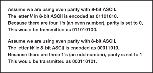
Parity Checking One of the oldest and simplest error-detection methods is parity.
With this technique, one additional bit is added to each byte in the message. The value
of this additional parity bit is based on the number of 1’s in each byte transmitted. This
parity bit is set to make the total number of 1’s in the byte (including the parity bit)
either an even number or an odd number. Figure 4.3 gives an example.
A little thought will convince you that any single error (a switch of a 1 to a 0 or
vice versa) will be detected by parity, but it cannot determine which bit was in error. You
will know an error occurred, but not what the error was. But if two bits are switched, the
4.3 ERROR CONTROL 127
FIGURE 4.3 Using parity for error
detection
parity check will not detect any error. It is easy to see that parity can detect errors only
when an odd number of bits have been switched; any even number of errors cancel one
another out. Therefore, the probability of detecting an error, given that one has occurred,
is only about 50 percent. Many networks today do not use parity because of its low
error-detection rate. When parity is used, protocols are described as having odd parity
or even parity.
Checksum With the checksum technique, a checksum (typically one byte) is added
to the end of the message. The checksum is calculated by adding the decimal value of
each character in the message, dividing the sum by 255, and using the remainder as the
checksum. The receiver calculates its own checksum in the same way and compares it
with the transmitted checksum. If the two values are equal, the message is presumed
to contain no errors. Use of checksum detects close to 95 percent of the errors for
multiple-bit burst errors.
Cyclical Redundancy Check One of the most popular error-checking schemes is
cyclical redundancy check (CRC). It adds 8, 16, 24, or 32 bits to the message. With
CRC, a message is treated as one long binary number, P. Before transmission, the
data link layer (or hardware device) divides P by a fixed binary number, G, resulting
in a whole number, Q, and a remainder, R/G. So, P/G = Q + R/G. For example, if
P = 58 and G = 8, then Q = 7andR = 2. G is chosen so that the remainder, R, will
be either 8 bits, 16 bits, 24 bits, or 32 bits.
1
The remainder, R, is appended to the message as the error-checking characters
before transmission. The receiving hardware divides the received message by the same
G, which generates an R. The receiving hardware checks to ascertain whether the received
R agrees with the locally generated R. If it does not, the message is assumed to be in error.
Cyclical redundancy check performs quite well. The most commonly used CRC
codes are CRC-16 (a 16-bit version), CRC-CCITT (another 16-bit version), and CRC-32
(a 32-bit version). The probability of detecting an error is 100% for all errors of the
same length as the CRC or less. For example, CRC-16 is guaranteed to detect errors if
1
CRC is actually more complicated than this because it uses polynominal division, not “normal” division as
illustrated here. Ross Willams provides an excellent tutorial on CRC at www.ross.net/crc/crcpaper.html.
128 CHAPTER 4 DATA LINK LAYER
16 or fewer bits are affected. If the burst error is longer than the CRC, then CRC is not
perfect but is close to it. CRC-16 will detect about 99.998 percent of all burst errors
longer than 16 bits, whereas CRC-32 will detect about 99.99999998 percent of all burst
errors longer than 32 bits.
4.3.4 Error Correction via Retransmission
Once error has been detected, it must be corrected. The simplest, most effective, least
expensive, and most commonly used method for error correction is retransmission. With
retransmission, a receiver that detects an error simply asks the sender to retransmit the
message until it is received without error. This is often called Automatic Repeat reQuest
(ARQ). There are two types of ARQ: stop-and-wait and continuous.
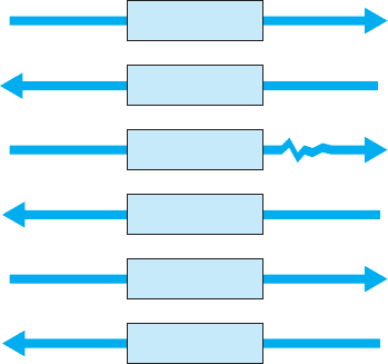
Stop-and-Wait ARQ With stop-and-wait ARQ, the sender stops and waits for a
response from the receiver after each data packet. After receiving a packet, the receiver
sends either an acknowledgment (ACK), if the packet was received without error, or a
negative acknowledgment (NAK), if the message contained an error. If it is an NAK,
the sender resends the previous message. If it is an ACK, the sender continues with the
next message. Stop-and-wait ARQ is by definition a half-duplex transmission technique
(Figure 4.4).
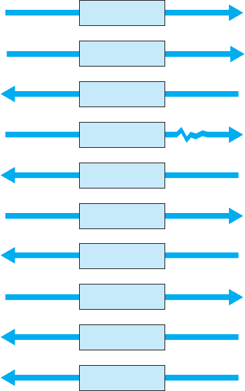
Continuous ARQ With continuous ARQ, the sender does not wait for an acknowledg-
ment after sending a message; it immediately sends the next one. Although the messages
are being transmitted, the sender examines the stream of returning acknowledgments. If
it receives an NAK, the sender retransmits the needed messages. The packets that are
retransmitted may be only those containing an error (called Link Access Protocol for
Modems [LAP-M]) or may be the first packet with an error and all those that followed
it (called Go-Back-N ARQ). LAP-M is better because it is more efficient.
Packet A
Sender Receiver
ACK
Packet B
NAK
Packet B
ACK
No errors
detected
Errors
detected
No errors
detected
FIGURE 4.4
Stop-and-wait ARQ
(Automatic Repeat reQuest).
ACK = acknowledgment;
NAK = negative
acknowledgment
4.3 ERROR CONTROL 129
Packet A
Sender Receiver
Packet B
ACK A
Packet C
ACK B
Packet D
No errors
detected
No errors
detected
NAK C
Packet C
ACK D
ACK C
No errors
detected
No errors
detected
Errors
detected
FIGURE 4.5
Continuous ARQ (Automatic
Repeat reQuest). ACK =
acknowledgment; NAK =
negative acknowledgment
Continuous ARQ is by definition a full-duplex transmission technique, because
both the sender and the receiver are transmitting simultaneously. (The sender is send-
ing messages, and the receiver is sending ACKs and NAKs.) Figure 4.5 illustrates the
flow of messages on a communication circuit using continuous ARQ. Continuous ARQ
is sometimes called sliding window because of the visual imagery the early network
designers used to think about continuous ARQ. Visualize the sender having a set of mes-
sages to send in memory stacked in order from first to last. Now imagine a window that
moves through the stack from first to last. As a message is sent, the window expands to
cover it, meaning that the sender is waiting for an ACK for the message. As an ACK
is received for a message, the window moves forward, dropping the message out of the
bottom of the window, indicating that it has been sent and received successfully.
Continuous ARQ is also important in providing flow control, which means
ensuring that the computer sending the message is not transmitting too quickly for the
receiver. For example, if a client computer was sending information too quickly for
a server computer to store a file being uploaded, the server might run out of memory
to store the file. By using ACKs and NAKs, the receiver can control the rate at which
it receives information. With stop-and-wait ARQ, the receiver does not send an ACK
until it is ready to receive more packets. In continuous ARQ, the sender and receiver

130 CHAPTER 4 DATA LINK LAYER
4.1
HOW FORWARD ERROR
CORRECTION WORKS
TECHNICAL
FOCUS
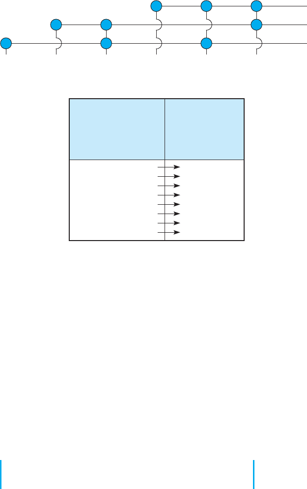
To see how error-correcting codes work, consider
the example of a forward error checking code in
Figure 4.6, called a Hamming code, after its inven-
tor, R. W. Hamming. This code is a very simple
approach, capable of correcting 1-bit errors. More
sophisticated techniques (e.g., Reed–Solomon) are
commonly used today, but this will give you a sense
of how they work.
The Hamming code associates even parity bits
with unique combinations of data bits. With a
4-data-bit code as an example, a character might
be represented by the data-bit configuration 1010.
Three parity bits,
P
1
,
P
2
,and
P
4
, are added, resulting
in a 7-bit code, shown in the upper half of Figure 4.6.
Notice that the data bits (
D
3
,
D
5
,
D
6
,
D
7
) are 1010 and
the parity bits (
P
1
,
P
2
,
P
4
) are 101.
As depicted in the upper half of Figure 4.6, parity
bit
P
1
applies to data bits
D
3
,
D
5
,and
D
7
. Parity bit
P
2
applies to data bits
D
3
,
D
6
,and
D
7
. Parity bit
P
4
applies to data bits
D
5
,
D
6
,and
D
7
. For the example,
in which
D
3
,
D
5
,
D
6
,
D
7
= 1010,
P
1
must equal 1
because there is only a single 1 among
D
3
,
D
5
and
D
7
and parity must be even. Similarly,
P
2
must be 0
because
D
3
and
D
6
are 1’s.
P
4
is 1 because
D
6
is the
only 1 among
D
5
,
D
6
,and
D
7
.
Now, assume that during the transmission, data
bit
D
7
ischangedfroma0toa1bylinenoise.
Because this data bit is being checked by
P
1
,
P
2
,and
P
4
, all 3 parity bits now show odd parity instead of
the correct even parity.
D
7
is the only data bit that is
monitored by all 3 parity bits; therefore, when
D
7
is in
error, all 3 parity bits show an incorrect parity. In this
way, the receiving equipment can determine which
bit was in error and reverse its state, thus correcting
the error without retransmission.
The lower half of the figure is a table that deter-
mines the location of the bit in error. A 1 in the table
means that the corresponding parity bit indicates a
parity error. Conversely, a 0 means the parity check
is correct. These 0’s and 1’s form a binary number
that indicates the numeric location of the erroneous
bit. In the previous example,
P
1
,
P
2
,and
P
4
checks all
failed, yielding 111, or a decimal 7, the subscript of
the erroneous bit.
usually agree on the size of the sliding window. Once the sender has transmitted the
maximum number of packets permitted in the sliding window, it cannot send any more
packets until the receiver sends an ACK.
4.3.5 Forward Error Correction
Forward error correction uses codes containing sufficient redundancy to prevent errors
by detecting and correcting them at the receiving end without retransmission of the
original message. The redundancy, or extra bits required, varies with different schemes.
It ranges from a small percentage of extra bits to 100% redundancy, with the number of
error-detecting bits roughly equaling the number of data bits. One of the characteristics
of many error-correcting codes is that there must be a minimum number of error-free
bits between bursts of errors.
Forward error correction is commonly used in satellite transmission. A round trip
from the earth station to the satellite and back includes a significant delay. Error rates can
fluctuate depending on the condition of equipment, sunspots, or the weather. Indeed, some
weather conditions make it impossible to transmit without some errors, making forward
error correction essential. Compared with satellite equipment costs, the additional cost
of forward error correction is insignificant.
4.4 DATA LINK PROTOCOLS 131
√ = Corresponding parity
check is correct
X = Corresponding parity
check fails
Determines in which
bit the error occured
P
4
P
2
P
1
√√√
√√
X
√ X √
√
XX
X
√√
X √ X
XX
√
XXX
no error
P
1
P
2
D
3
P
4
D
5
D
6
D
7
P
1
P
2
D
3
P
4
D
5
D
6
1011010
Checking relations between parity bits (P) and data bits (D)
Interpreting parity bit patterns
FIGURE 4.6
Hamming code for
forward error correction
4.3.6 Error Control in Practice
In the OSI model (see Chapter 1), error control is defined to be a layer-2 function—it
is the responsibility of the data link layer. However, in practice, we have moved away
from this. Most network cables—especially LAN cables—are very reliable and errors
are far less common than they were in the 1980s.
Therefore, most data link layer software used in LANs (i.e., Ethernet) is configured
to detect errors, but not correct them. Any time a packet with an error is discovered, it
is simply discarded. Wireless LANs and some WANs, where errors are more likely, still
perform both error detection and error correction.
The implication from this is that error correction must be performed by software
at higher layers. This software must be able to detect lost packets (i.e., those that have
been discarded) and request the sender to retransmit them. This is commonly done by
the transport layer using continuous ARQ as we shall see in the next chapter.
4.4 DATA LINK PROTOCOLS
In this section, we outline several commonly used data link layer protocols, which are
summarized in Figure 4.7. Here we focus on message delineation, which indicates where
a message starts and stops, and the various parts or fields within the message. For
example, you must clearly indicate which part of a message or packet of data is the
132 CHAPTER 4 DATA LINK LAYER
*
Varies depending on the message length.
ARQ = Automatic Repeat reQuest; CRC = cyclical redundancy check; HDLC = high-level data link control; PPP =
Point-to-Point Protocol; SDLC = s
y
nchronous data link control.
FIGURE 4.7 Protocol summary
error-control portion; otherwise, the receiver cannot use it properly to determine if an
error has occurred. The data link layer performs this function by adding a PDU to the
packet it receives from the network layer. This PDU is called a frame.
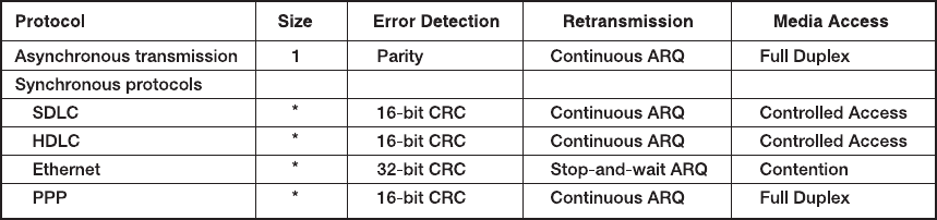
4.4.1 Asynchronous Transmission
Asynchronous transmission isoftenreferredtoasstart-stop transmission because
the transmitting computer can transmit a character whenever it is convenient, and the
receiving computer will accept that character. It is typically used on point-to-point
full-duplex circuits (i.e., circuits that have only two computers on them), so media
access control is not a concern. If you use VT100 protocol, or connect to a UNIX or
Linux computer using Telnet, chances are you are using asynchronous transmission.
With asynchronous transmission, each character is transmitted independently of all
other characters. To separate the characters and synchronize transmission, a start bit and
a stop bit are put on the front and back of each individual character. For example, if we
are using 7-bit ASCII with even parity, the total transmission is 10 bits for each character
(1 start bit, 7 bits for the letter, 1 parity bit, 1 stop bit).
The start bit and stop bit are the opposite of each other. Typically, the start bit is a 0
and the stop bit is a 1. There is no fixed distance between characters because the terminal
transmits the character as soon as it is typed, which varies with the speed of the typist.
The recognition of the start and stop of each message (called synchronization) takes
place for each individual character because the start bit is a signal that tells the receiver
to start sampling the incoming bits of a character so the data bits can be interpreted into
their proper character structure. A stop bit informs the receiver that the character has
been received and resets it for recognition of the next start bit.
When the sender is waiting for the user to type the next character, no data are sent;
the communication circuit is idle. This idle time really is artificial—some signal always
must be sent down the circuit. For example, suppose we are using a unipolar digital
signaling technique where +5 volts indicates a 1 and 0 volts indicates a 0 (see Chapter 3).
Even if we send 0 volts, we are still sending a signal, a 0 in this case. Asynchronous
transmission defines the idle signal (the signal that is sent down the circuit when no data
4.4 DATA LINK PROTOCOLS 133
0V
+3V
0
11
1010 110
Idle Idle
Stop
bit
Parity
bit
7bit ASCII data
Start
bit
FIGURE 4.8
Asynchronous transmission.
ASCII = United States of
America Standard Code for
Information Interchange
are being transmitted) as the same as the stop bit. When the sender finishes transmitting
a letter and is waiting for more data to send, it sends a continuous series of stop bits.
Figure 4.8 shows an example of asynchronous transmission.
Some older protocols have two stop bits instead of the traditional single stop bit.
The use of both a start bit and a stop bit is changing; some protocols have eliminated
the stop bit altogether.
4.4.2 Synchronous Transmission
With synchronous transmission, all the letters or data in one group of data are transmit-
ted at one time as a block of data. This block of data is called a frame. For example, a
terminal or personal computer will save all the keystrokes typed by the user and transmit
them only when the user presses a special “transmit” key. In this case, the start and end
of the entire frame must be marked, not the start and end of each letter. Synchronous
transmission is often used on both point-to-point and multipoint circuits. For multipoint
circuits, each packet must include a destination address and a source address, and media
access control is important.
The start and end of each frame (synchronization) sometimes is established by
adding synchronization characters (SYN) to the start of the frame. Depending on the
protocol, there may be anywhere from one to eight SYN characters. After the SYN
characters, the transmitting computer sends a long stream of data that may contain thou-
sands of bits. Knowing what code is being used, the receiving computer counts off the
appropriate number of bits for the first character, assumes this is the first character, and
passes it to the computer. It then counts off the bits for the second character, and so on.
In summary, asynchronous data transmission means each character is transmitted
as a totally independent entity with its own start and stop bits to inform the receiving
computer that the character is beginning and ending. Synchronous transmission means
whole blocks of data are transmitted as frames after the sender and the receiver have
been synchronized.
There are many protocols for synchronous transmission. We discuss four commonly
used synchronous data link protocols.
Synchronous Data Link Control Synchronous data link control (SDLC) is a
mainframe protocol developed by IBM in 1972 that is still in use today. It uses a
controlled-access media access protocol. If you use a 3270 protocol, you’re using SDLC.
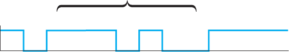
Figure 4.9 shows a typical SDLC frame. Each SDLC frame begins and ends with
a special bit pattern (01111110), known as the flag. The address field identifies the
destination. The length of the address field is usually 8 bits but can be set at 16 bits; all
computers on the same network must use the same length. The control field identifies the
134 CHAPTER 4 DATA LINK LAYER
8 bits32 bitsVariable
length
8 bits8 bits
Flag FlagAddress Control Message
8 bits
Frame check
sequence
FIGURE 4.9 SDLC
(synchronous data link control)
frame layout
kind of frame that is being transmitted, either information or supervisory. An information
frame is used for the transfer and reception of messages, frame numbering of contiguous
frames, and the like. A supervisory frame is used to transmit acknowledgments (ACKs
and NAKs). The message field is of variable length and is the user’s message. The frame
check sequence field is a 32-bit CRC code (some older versions use a 16-bit CRC).
High-Level Data Link Control High-level data link control (HDLC) is a formal
standard developed by the ISO often used in WANs. HDLC is essentially the same as
SDLC, except that the address and control fields can be longer. HDLC also has several
additional benefits that are beyond the scope of this book, such as a larger sliding window
for continuous ARQ. It uses a controlled-access media access protocol. One variant,
Link Access Protocol–Balanced (LAP-B), uses the same structure as HDLC but is a
scaled-down version of HDLC (i.e., provides fewer of those benefits mentioned that are
“beyond the scope of this book”). A version of HDLC called Cisco HDLC (cHDLC)
includes a network protocol field. cHDLC and HDLC have gradually replaced SDLC.
Ethernet Ethernet is a very popular LAN protocol, conceived by Bob Metcalfe in
1973 and developed jointly by Digital, Intel, and Xerox in the 1970s. Since then, Ethernet
has been further refined and developed into a formal standard called IEEE 802.3ac. There
are several versions of Ethernet in use today. Ethernet uses a contention media access
protocol.
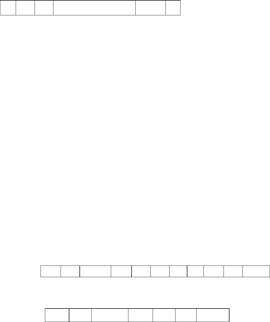
There are several standard versions of Ethernet. Figure 4.10a shows an Ethernet
803.3ac frame. The frame starts with a 7-byte preamble which is a repeating pattern of
ones and zeros (10101010). This is followed by a start of frame delimiter, which marks
the start of the frame. The destination address specifies the receiver, whereas the source
address specifies the sender. The length indicates the length in 8-bit bytes of the message
portion of the frame. The VLAN tag field is an optional 4-byte address field used by
virtual LANs (VLANs), which are discussed in Chapter 7. The Ethernet frame uses this
Preamble
7
bytes
Start of
Frame
1
byte
Destination
Address
6
bytes
Source
Address
6
bytes
VLAN
Tag
4
bytes
Length
2
bytes
Control
1-2
bytes
Data
46-1,500
bytes
Frame Check
Sequence
4
bytes
DSAP
1
byte
SSAP
1
byte
FIGURE 4.10a Ethernet 802.3ac frame layout
Preamble
7
bytes
Start of
Frame
1
byte
Destination
Address
6
bytes
Source
Address
6
bytes
2
bytes
Type
46-1,500
bytes
Frame Check
Sequence
4
bytes
Data
FIGURE 4.10b Ethernet II frame layout