FitzGerald J., Dennis A., Durcikova A. Business Data Communications and Networking
Подождите немного. Документ загружается.

A.2 NULL MODEM CABLE CONNECTIONS 485
37-pin connector
main channel
DB-9
9-pin connector
secondary channel
37-Pin Connector 9-Pin Connector
Pin
First Segment
Assignment Function
PinPin Function
Second Segment
Assignment Function
1
2
3
4
5
6
7
8
9
10
11
12
13
14
15
16
17
18
19
Shield
Signaling rate indicator
(Unassigned)
Send data
Send timing
Receive data
Request to send
Receive timing
Clear to send
Local loopback
Data mode
Terminal ready
Receiver ready
Remote loopback
Incoming call
Select frequency/signaling
rate selector
Terminal timing
Test mode
Signal ground
20
21
22
23
24
25
26
27
28
29
30
31
32
33
34
35
36
37
Receive common
(Unassigned)
Send data ready
Send timing
Receive data
Request to send
Receive timing
Clear to send
Terminal in service
Data mode
Terminal ready
Receiver ready
Select standby
Signal quality
New signal
Terminal timing
Standby indicator
Send common
1
2
3
4
5
6
7
8
9
Shield
Secondary receiver
Secondary send data
Secondary receive data
Signal ground
Receive common
Secondary request to send
Secondary clear to send
Send common
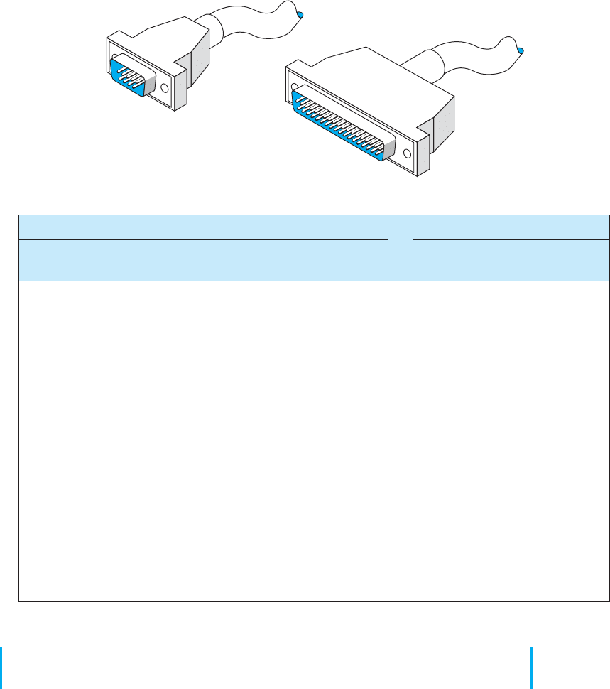
FIGURE A.2 RS449 cable specifications
A.2 NULL MODEM CABLE CONNECTIONS
Null modem cables allow transmission between two computers that are next to each other
(6 to 8 feet apart) without using a modem. If you discover that the diskette from your
computer will not fit into another one, that transmitting over telephone lines is impossible,
or that you cannot transmit data easily from one computer to another for any reason,
then it is time to get a null modem cable.
486 APPENDIX A CONNECTOR CABLES
TXD Transmit data
RXD Receive data
RTS Request to send
CTS Clear to send
DSR Data set ready
SG Signal ground
CD Carrier detect
DTR Data terminal ready
RI Ring indicator
CD Carrier detect (used by a modem to indicate
the presence of a carrier signal)
DSR Data set ready
RXD Receive data
RTS Request to send
XD Transmit data
CTS Clear to send
DTR Data terminal ready
RI Ring indicator
SG Signal ground
1
2
3
4
5
6
7
8
9
10
11
12
13
14
15
16
17
18
19
20
21
22
23
24
25
1
2
3
4
5
6
7
8
9
10
11
12
13
14
15
16
17
18
19
20
21
22
23
24
25
1
2
3
4
5
6
7
8
9
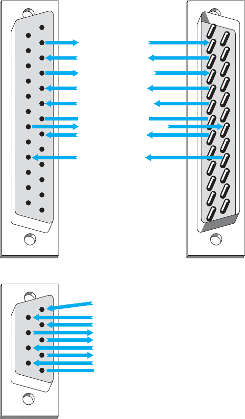
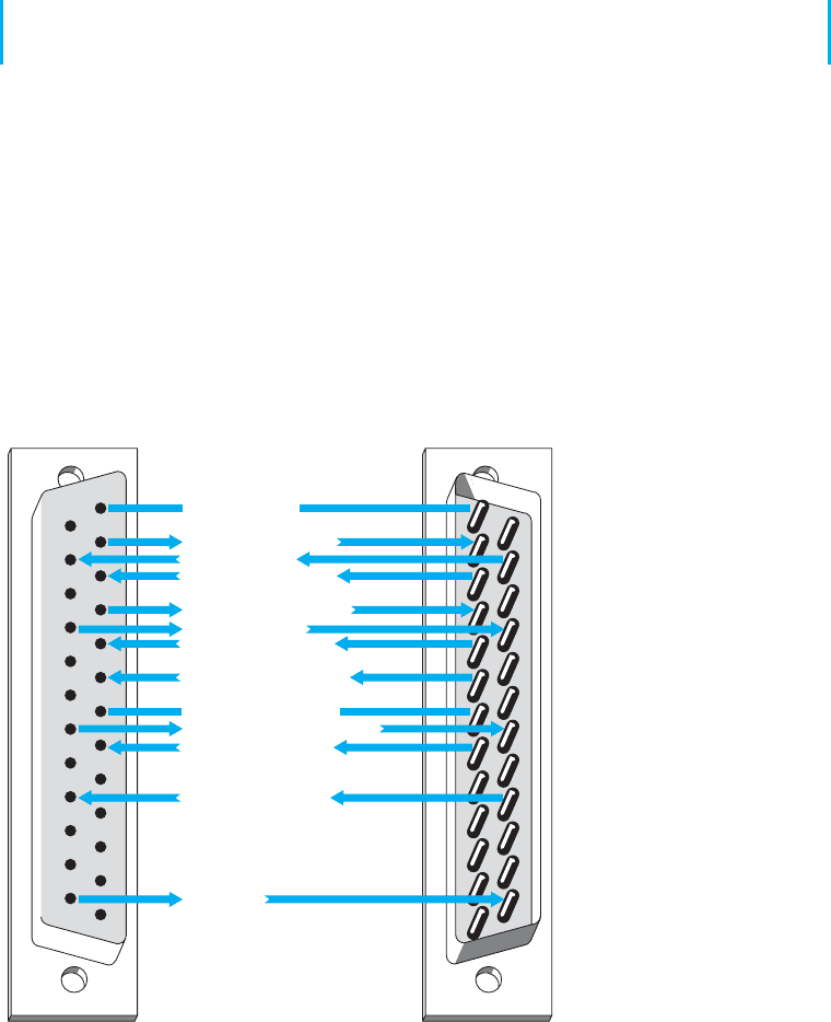
FIGURE A.3 Pin configurations
First, bring the two computers close together. Next, obtain a null modem cable
(more on the pin connections shortly). The cable runs from the serial communication
port on the first computer to the serial communication port on the second one. The cable
is called a null modem cable because it eliminates the need for a modem. You can either
build a null modem cable or buy one from any computer store. Null modem connector
blocks are available to connect between two cables you already own.
To transfer data between two computers, just hook the null modem cable between
them and call up one of the computers by using the communication software you
A.3 DATA SIGNALING/SYNCHRONIZATION 487
normally use. To do so, put one computer in answer mode and use the other one to
call it, but skip the step of dialing the telephone number. After the receiving com-
puter has answered that it is ready, the data can be sent, just as you would on a
normal long-distance dial-up connection. Basically, a null modem cable switches pins
2 and 3 (Transmit and Receive) of the RS232 connector plug.
A.3 DATA SIGNALING/SYNCHRONIZATION
Let us look at data signaling or synchronization as it occurs on a RS232 connector cable.
Figure A.4 shows the 13 most frequently used pins of the 25-pin RS232 connector cable.
A computer is on the left side of the figure and a modem is on the right.
Do you ever wonder what happens when you press the “send” key to transmit
synchronous data? When a synchronous block of data is sent, the computer and the
modem raise and lower electrical signals (plus and minus polarity) between themselves
over the RS232 connector. This is usually a nominal +12 or −12 volts. For example, a
modem with a RS232 interface might indicate that it is on and ready to operate by raising
the signal on pin 6, Data set ready. (Data set is an older term for a modem.) When a call
comes in, the modem shows the computer that the telephone line is ringing by raising
a signal on pin 22, the Ring indicator. Raising a signal means putting +12 volts on the
TXD Transmit data
RXD Receive data
RTS Request to send
CTS Clear to send
DSR Data set ready
SG Signal ground
CD Carrier detect
DTR Data terminal ready
RI Ring indicator
1
2
3
4
5
6
7
8
9
10
11
12
13
14
15
16
17
18
19
20
21
22
23
24
25
1
2
3
4
5
6
7
8
9
10
11
12
13
14
15
16
17
18
19
20
21
22
23
24
25
Frame ground
Receive clock
Transmit clock
Test/busy
Computer DTE side Name and pin number Modem DCE side
FIGURE A.4 Data signaling with
RS232 cables. DCE 1-1-data circuit
terminating equipment: DTE 1-1-data
terminal equipment

488 APPENDIX A CONNECTOR CABLES
wire or pin. The computer may then tell the modem to answer the call by raising a signal
on pin 20, Data terminal ready. After the modems connect, the modem may indicate the
connection status to the computer by raising a signal on pin 8, Carrier detect. At the
end of the session, the microcomputer may tell the modem to drop the telephone call
(release the circuit) by lowering the signal on pin 20, Data terminal ready. The Request
to send and Clear to send signals go over pins 4 and 5, respectively, which are used
in half-duplex modems to manage control of the communication channel. Incidentally,
some of these basic procedures may vary slightly from one manufacturer to another.
Follow the pins and signal direction arrows in Figure A.4 as we discuss an example
that handles the flow of a block of synchronous data. When the computer operator presses
the “send” key to transmit a block of data, pin 4, Request to send, transmits the signal
from the computer to the modem. This informs the modem that a block of data is ready
to be sent. The modem then sends a Clear to send signal back to the computer by using
pin 5, thus telling the computer that it can send a synchronous block of data.
The computer now outpulses a serial stream of bits that contain two 8-bit SYN
characters in front of the message block. A SYN character is 0110100 (decimal 22 in
ASCII code). This bit stream passes over the connector cable to the modem using pin 2,
Transmit data. The modem then modulates this data block to convert it from the digital
signal (plus and minus polarity) to an analog signal (discussed in the next section). From
the modem, the data go out onto the local loop circuit between your business premises
and the telephone company central office. From there, it goes to the long-distance IXC
and the receiving end’s telephone company central office. Then it moves to the local
loop, into the modem, across the connector cable, and into the server at the other end of
the circuit.
This process is repeated for each synchronous message block in half-duplex trans-
mission. The data signaling that takes place between the computer and the modem
involves the Request to send, Clear to send, and Transmit data pins. Accurate timing
between blocks of data is critical in data signaling and synchronization. If this timing is
lost, the entire block of data is destroyed and must be retransmitted.
A.4 ETHERNET AND RJ–45
A.4.1 10Base-T
Ethernet 10Base-T is most often wired with cat 5 cable, which has four pairs of wire in
each cable, but only two pairs are used so that cat 3 cable can still be used if desired.
One pair of two wires is used to transmit from the computer to the hub (or switch),
while the other pair of two wires is used to receive data from the hub (or switch). Both
wires in each pair transmit the same signal but with opposite polarity; the transmit +
wire uses positive charges while the transmit—uses negative charges. This redundancy
helps reduce errors and also reduces interference between the wires in the pair. Thus,
10Base-T is capable of full-duplex transmission at the hardware level, but it usually is
only implemented as half-duplex.
A.4 ETHERNET AND RJ–45 489
Pin number
1
2
3
4
5
6
7
8
White with orange stripe
Orange with white stripe or solid orange
White with green stripe
Blue with white stripe or solid blue
White with blue stripe
Green with white stripe or solid green
White with brown stripe or solid brown
Brown with white stripe or solid brown
Transmit +
Transmit –
Receive +
Not used
Not used
Receive –
Not used
Not used
Color (EIA/TIA 568B standard) Name
FIGURE A.5 Pins used by
10Base-T and 100Base-T at the
computer end
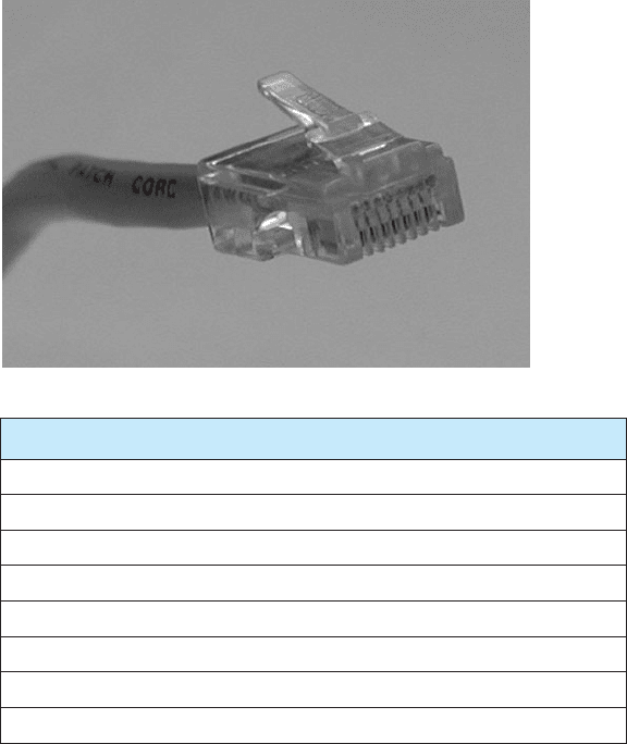
Figure A.5 shows the way in which cat 5 cables are wired. The cable is wired into
an RJ–45 connector,
1
which is an 8-pin connector used to plug into NICs, hubs, and
switches. Pins 1 and 2 are the wires used to transmit from the computer’s NIC while pins
3 and 6 are used to receive transmissions at the computer’s NIC. The pins on the hub
or switch are reversed; that is, pins 1 and 2 deliver the computer’s NIC’s transmissions,
so they are the receive pins at the hub or switch, while 3 and 6 are the receive pins at
the hub or switch. Any time you want to directly connect two computer NICs or two
hubs/switches, you must use a crossover cable, which connects pins 1 and 2 at one end
to pins 3 and 6 at the other (and vice versa).
1
To be very precise, it is not an RJ-45 connector, but rather a version of the RJ-45 designed for network use.
The RJ-45 is designed for telephone use, which tolerates higher interference. Just about everyone calls it an
RJ-45 connector, but if you ever buy a “real” RJ-45 connector designed for telephone use and try to build a
LAN cable yourself to save a few dollars, it won’t work.
490 APPENDIX A CONNECTOR CABLES
In order to successfully send and receive messages, both the sender and receiver
have to agree how bits will be transmitted over the specific wires in the cable. They
must understand both how fast the data will be sent and what electrical voltages will be
used to represent a binary 1 and a binary 0. 10Base-T transmits at a rate of 10 Mbps,
or 10 million bits per second. This means that the computers divide each second into
10 million time periods in which they can send data. Each time period (100 nanoseconds
[i.e., 100 billionths of a second]) contains one bit, either binary 1 or a binary 0. Thus
each wire in the cat 3 or cat 5 cable must be capable of carrying a signal that changes
10 million times per second; we call this a signaling rate of 10 million Hertz, or 10 MHz.
One of the challenges in transmitting this fast is making sure that the clock at
the receiver is synchronized with the clock at the sender so they can both understand
when one of these 100-nanosecond time periods starts and stops. This is done by using
Manchester encoding, a special type of signaling in which the signal is changed from
high voltage (2 volts) to low voltage (0 volts) or vice versa in the middle of the signal.
A change from low to high is used to represent a 1, while the opposite (a change from
high to low) is used to represent a 0. Thus, in the exact middle of each time period, the
signal voltage changes. This “heartbeat” synchronizes the clocks.
A.4.2 100Base-T
Ethernet 100Base-T also transmits data over cat 5 cables. It uses exactly the same wiring
and connector pin configurations as 10Base-T so that the wiring for the two types of
LANs is identical.
100Base-T does not use Manchester encoding. 100Base-T uses 4B5B coding, in
which the data are sent in groups of 5 bits, the first 4 of which are data and the last one
is used for clock synchronizing purposes and to minimize interference. The fifth bit is
chosen to ensure than no more than 4 out of the 5 bits have the same value. Because of
the high speed at which the data is being transmitted, a long series of all ones or all zeros
would result in a long transmission of positive or negative voltage, which has a greater
chance of causing interference to other wires than an alternating positive and negative
pattern of voltages. Also, without regular changes in signal as is done in Manchester
encoding, it becomes increasingly difficult to ensure that the clocks on the sender and
receiver are synchronized. Adding this extra fifth bit every 4 bits of data ensures no long
single-level transmissions are sent and ensures a transition for clock synchronizing.
In order to achieve a data rate of 100 Mbps when using 4B5B, the sender and
receiver have to operate at 125 MHz, because only 4 out of every 5 bits transmitted con-
tain data. 100Base-T uses a technique called Multi-Level Transmission–3 Level (MLT-3)
to transmit the 4B5B codes through the cable. With MLT-3, three levels of voltage are
defined, +1 volts, 0 volts, and −1 volts. MLT-3 is based on changes in voltages like
Manchester encoding, but in a different way. To send a binary zero, MLT-3 simply
maintains the same voltage as used in the previous time slot. To transmit a binary 0, the
voltage is changed to an adjacent level (e.g., from −1to0or0to+1).
A.4.3 1 GbE
The version of 1 GbE that runs over twisted-pair cables is called 1000Base-T and runs
over one cat 5 cable by using parallel transmission. That is, it uses each of the four pairs

A.5 UNIVERSAL SERIAL BUS 491
of wires in the cat 5 cable as a separate half-duplex circuit with a transmit and receive
wire pair. We now have four parallel circuits running through one cable, so in each clock
tick we can send four signals at a time through the cable. 100Base-T Ethernet uses a
4B5B coding scheme in which the set of 5 bits (4 data, one overhead) were transmitted
at 125 MHz (i.e., 125 million times per second), giving a speed of 100 Mbps. 125 MHz
is the fastest data rate at which the wires in cat 5 can reliably transmit for any reasonable
distance. However, 125 MHz times 4 bits per signal equals only 500 Mbps. In order to
get 1000 Mbps, we have to do something more creative.
Until now, we talked about transmitting one bit in each time interval by using a
higher voltage and a lower voltage (e.g., see Manchester encoding). Gigabit Ethernet
uses the same 125 MHz clock speed as 100Base-T Ethernet, but sends 2 bits in each
time interval using Pulse Amplitude Modulation–5 (PAM-5). With PAM-5, five different
voltage levels are defined, ranging from +1 volts to −1 volts. Four of these voltage levels
are used to send data. One voltage is defined to be the 2-bit pattern 00, another is defined
to be 01, another 10, and another 11. The fifth voltage level is used for the fifth control
bit. So, in each time period, the sender sends one electrical pulse at one of the five
defined voltages, which represents a certain pattern of 2 bits, rather than just 1 bit as
with Manchester encoding. Two bits per time interval times 125 time intervals per second
times four separate circuit pairs in each cat 5 cable equals 1000 Mbps.
Because we are now sending 2 bits per signal using five different voltage levels
rather than just two voltage levels as with Manchester encoding or 4B5B, the signal is
more susceptible to noise or interference. This is because it is more difficult for the NIC
to distinguish among differences in five voltage levels rather than two voltage levels
because the differences between levels are smaller. It takes a much smaller amount of
noise to trick the NIC into thinking a signal sent at one voltage level is actually a different
level. For this reason, most organizations use cat 5e cable for 100Base-T; cat 5e is a
version of cat 5 cable specially modified to reduce errors when used in 1000Base-T
installations. Cat 6 cable has also been proposed, which has a capacity of 250 MHz. The
maximum length of cat 5/5e/6 cable for 1000Base-T is 100 meters from the computer to
the hub or switch.
A.5 UNIVERSAL SERIAL BUS
Universal Serial Bus (USB) is another commonly used data transfer standard. Older
USB devices will support serial data transfer at either 1.5 Mbps or 12 Mbps. Devices that
conform to the USB 2.0 standard will support both these older speeds, plus 480 Mbps,
which is sometimes called Hi-Speed USB.
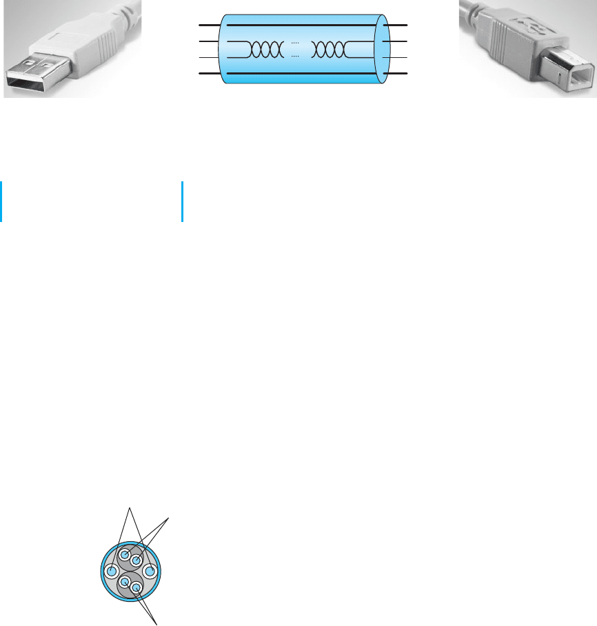
USB cables have a host end and a device end, each of which have different styles
of connectors (Figure A.6). Inside the cable, there are four wires. One is a ground wire
and one (VBUS) is used to send a +5 volt power signal to the USB device. The two D
wires are used to transmit the data in two separate serial data streams using a nonreturn
to zero technique. The D+ wire sends the data with a positive charge while the D-
wire sends the identical data with an offsetting negative charge to reduce interference
and error.
492 APPENDIX A CONNECTOR CABLES
VBUS
D+
D–
GND
VBUS
D+
D–
GND
Series A Connectors
used at the Host System end
Series B Connectors
used at the USB Device end
FIGURE A.6 USB cables
A.6 FIREWIRE
Firewire, a competitor to USB, was originally developed by Apple computer in the early
1990s and was standardized as IEEE 1394a-2000. Like USB, it is a serial bus connector.
Firewire is also called i.Link.
Modern 1394a-2000 Firewire devices will support serial data transfer at 400 Mbps.
Firewire cables have either a 4-pin or 6-pin configuration with a variety of different types
of connectors. Inside the cable there are six wires (Figure A.7). Two are used to send
8–40 volts of power to the Firewire device. The other wires are two pairs of two wires
used to transmit the data in two separate serial data streams using a nonreturn to zero
technique. Within each pair, the D+ wire sends the data with a positive charge while the
D- wire sends the identical data with an offsetting negative charge to reduce interference
and error.
Because there are two pairs of wires, Firewire could be configured to transmit in
parallel, but it is not. Instead, one pair of wires is used to send data and the other pair is
used to continuously send clocking signals to minimize the chance of error.
Power
Pair 1
Pair 2Cable
FIGURE A.7 Firewire cables
APPENDIX B
SPANNING TREE
PROTOCOL
Redundancy is an important element of good network design (see Chapter 12). Redundant
circuits and devices mean that the network can continue to operate even if one circuit or
device fails. For example, if a device has a 99.99 percent reliability, there is a .01 percent
chance of failing. This means on average that the device will fail for about one hour
per year. With two devices, the reliability increases to 99.9999 percent, or less than one
minute of expected downtime per year.
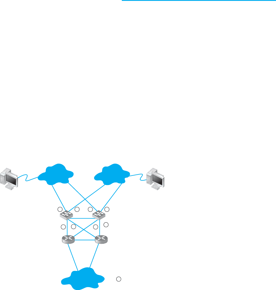
Figure B.1 shows a common redundant network design. Two LAN segments (LAN 1
and LAN 2) are connected to two separate switches (A and B), that are in turn connected
to two separate routers (X and Y) connected to the corporate WAN. Each switch has
4 ports; port 1 on switch A connects to LAN 1, port 2 connects to LAN 2, port 3 connects
to router X, and port 4 connects to router Y. In this way, both LAN 1 and LAN 2 can
continue to operate and send messages to and from each other and the WAN if any one
circuit or device fails. For example, if switch A fails, all traffic into LAN 1 can still flow
Switch A Switch B
4
Router X Router Y
LAN 1 LAN 2
Client
Server
WAN
4
33
1
1
211
Indicates port number 1, 2,
etc., on each switch
FIGURE B.1 Network
design with redundant
circuits and devices.
LAN = local area network;
WAN = wide area network
494 APPENDIX B SPANNING TREE PROTOCOL
through switch B. Likewise, if router X fails, if the circuit from switch A to router X
fails, or if port 3 on switch A fails, then traffic can flow through switch A to router Y
and then into the WAN.
The challenge with redundant designs is to prevent broadcast storms. Remember
that when switches are first turned on, they act like bridges, sending all messages in
all directions, until they learn which device can be reached through which port (see
Chapter 6). This means, for example, when the network in Figure B.1 is first turned on,
neither switch A nor switch B will know where any device is. Assume that the client
computer wants to send a message to the server. The message will enter LAN 1 from the
client computer and be sent to switch A via the circuit connected to switch A’s port 1.
Switch A will learn that the client is on port 1. It won’t know where the server is, so
it will forward the packet on all remaining ports (2, 3, and 4). Router X on port 3 and
router Y on port 4 will read the Ethernet address and ignore the message because it is
not addressed to them. Eventually, the message will reach the server on LAN 2 via the
message sent on port 2. The server will receive the message and send a response message
to the client. The response message will hit switch A on port 2 (switch A will learn that
the server is on port 2) and it will forward the response message to the client via port 1.
So far, so good. Now the problems start. Switch B is also on LAN 1, so it too will
receive the very first message sent by the client, and will do exactly the same thing as
switch A: it will learn that the client is on its port 1, and forward the message on its
ports 2, 3, and 4. Once again, routers X and Y will ignore the message because it is not
addressed to them (although the duplicate message has used up some of their processing
capacity needlessly). When the message is sent to LAN 2 via port 2, the server sees it
and starts to process it; we now have a duplicate message being processed twice.
But it gets worse. Switch A is also on LAN 2, so it receives all messages sent on
LAN 2. When switch B sends the message from the client to the server into LAN 2,
switch A also receives it, this time on its port 2. It now learns that the client is on port 2
(not port 1 as it originally thought; it assumes the computer has moved and updates its
forwarding table), and promptly forwards the message a second time to the server on all
remaining ports (1, 3, and 4). Routers X and Y see the message a third time and ignore it,
but because switch B is also on LAN 1, it picks up the message again, thinks it is a new
message, and again transmits the message on all other ports, which, of course, means
that switch A gets the message again and forwards it again, and therefore switch B gets
it again and forwards it, and so on, in a never-ending cycle. The same thing happens with
the response message from the server to the client, and in fact, with all messages. They
circulate forever through the circular loops in the redundant network, until the network
collapses under the storm.
1
The solution is to have switches configured with these redundant physical loops,
but to create a way for the switches to recognize these physical loops and block them
so that we create a different logical topology that does not have a loop. The method
used to create this logical topology is called the spanning tree protocol and has been
standardized as IEEE 802.1D.
1
You may recall that an IP packet has a maximum hop count (also called time to live) to prevent this endless
looping (see Chapter 5). Switches operate at the data link layer and therefore do not read the IP packet; the
maximum hop count won’t prevent looping at this layer.